EP2042318A1 - Procédé d'impression par jet d'encre - Google Patents
Procédé d'impression par jet d'encre Download PDFInfo
- Publication number
- EP2042318A1 EP2042318A1 EP20080165234 EP08165234A EP2042318A1 EP 2042318 A1 EP2042318 A1 EP 2042318A1 EP 20080165234 EP20080165234 EP 20080165234 EP 08165234 A EP08165234 A EP 08165234A EP 2042318 A1 EP2042318 A1 EP 2042318A1
- Authority
- EP
- European Patent Office
- Prior art keywords
- particles
- ink
- polymer micro
- image
- polymer
- Prior art date
- Legal status (The legal status is an assumption and is not a legal conclusion. Google has not performed a legal analysis and makes no representation as to the accuracy of the status listed.)
- Granted
Links
- 238000000034 method Methods 0.000 title claims abstract description 58
- 239000002245 particle Substances 0.000 claims abstract description 181
- 229920000642 polymer Polymers 0.000 claims abstract description 179
- 239000011859 microparticle Substances 0.000 claims abstract description 135
- 239000000463 material Substances 0.000 claims abstract description 72
- 238000010438 heat treatment Methods 0.000 claims abstract description 64
- 239000002904 solvent Substances 0.000 claims abstract description 59
- 238000004040 coloring Methods 0.000 claims abstract description 58
- 239000000203 mixture Substances 0.000 claims abstract description 58
- 238000000151 deposition Methods 0.000 claims abstract description 33
- XLYOFNOQVPJJNP-UHFFFAOYSA-N water Substances O XLYOFNOQVPJJNP-UHFFFAOYSA-N 0.000 claims abstract description 24
- 239000003960 organic solvent Substances 0.000 claims abstract description 15
- 238000003860 storage Methods 0.000 claims abstract description 15
- 238000012546 transfer Methods 0.000 claims description 144
- 239000007788 liquid Substances 0.000 claims description 90
- 238000009826 distribution Methods 0.000 claims description 20
- 230000004931 aggregating effect Effects 0.000 claims description 10
- 239000000976 ink Substances 0.000 description 159
- 239000002609 medium Substances 0.000 description 85
- 239000000049 pigment Substances 0.000 description 79
- 230000008021 deposition Effects 0.000 description 22
- 238000004140 cleaning Methods 0.000 description 19
- 239000010408 film Substances 0.000 description 19
- 239000006185 dispersion Substances 0.000 description 18
- 239000007787 solid Substances 0.000 description 18
- 230000000694 effects Effects 0.000 description 17
- 239000011347 resin Substances 0.000 description 17
- 229920005989 resin Polymers 0.000 description 17
- PPBRXRYQALVLMV-UHFFFAOYSA-N Styrene Chemical compound C=CC1=CC=CC=C1 PPBRXRYQALVLMV-UHFFFAOYSA-N 0.000 description 16
- ZWEHNKRNPOVVGH-UHFFFAOYSA-N 2-Butanone Chemical compound CCC(C)=O ZWEHNKRNPOVVGH-UHFFFAOYSA-N 0.000 description 15
- 230000009286 beneficial effect Effects 0.000 description 14
- 230000008569 process Effects 0.000 description 12
- 230000007547 defect Effects 0.000 description 11
- 239000013557 residual solvent Substances 0.000 description 11
- 238000011156 evaluation Methods 0.000 description 10
- MTHSVFCYNBDYFN-UHFFFAOYSA-N diethylene glycol Chemical compound OCCOCCO MTHSVFCYNBDYFN-UHFFFAOYSA-N 0.000 description 9
- 239000010410 layer Substances 0.000 description 9
- PEDCQBHIVMGVHV-UHFFFAOYSA-N Glycerine Chemical compound OCC(O)CO PEDCQBHIVMGVHV-UHFFFAOYSA-N 0.000 description 8
- 230000001070 adhesive effect Effects 0.000 description 8
- 230000015572 biosynthetic process Effects 0.000 description 8
- 239000003995 emulsifying agent Substances 0.000 description 8
- 238000002474 experimental method Methods 0.000 description 8
- 238000004448 titration Methods 0.000 description 8
- NBIIXXVUZAFLBC-UHFFFAOYSA-N Phosphoric acid Chemical group OP(O)(O)=O NBIIXXVUZAFLBC-UHFFFAOYSA-N 0.000 description 7
- 239000000853 adhesive Substances 0.000 description 7
- 239000003086 colorant Substances 0.000 description 7
- 238000001914 filtration Methods 0.000 description 7
- 239000001993 wax Substances 0.000 description 7
- HEMHJVSKTPXQMS-UHFFFAOYSA-M Sodium hydroxide Chemical compound [OH-].[Na+] HEMHJVSKTPXQMS-UHFFFAOYSA-M 0.000 description 6
- 230000000052 comparative effect Effects 0.000 description 6
- 230000008602 contraction Effects 0.000 description 6
- 239000003094 microcapsule Substances 0.000 description 6
- -1 polytetrafluoroethylene Polymers 0.000 description 6
- 239000004094 surface-active agent Substances 0.000 description 6
- LYCAIKOWRPUZTN-UHFFFAOYSA-N Ethylene glycol Chemical compound OCCO LYCAIKOWRPUZTN-UHFFFAOYSA-N 0.000 description 5
- 238000004873 anchoring Methods 0.000 description 5
- 125000000129 anionic group Chemical group 0.000 description 5
- 239000003795 chemical substances by application Substances 0.000 description 5
- 239000011362 coarse particle Substances 0.000 description 5
- XCJYREBRNVKWGJ-UHFFFAOYSA-N copper(II) phthalocyanine Chemical compound [Cu+2].C12=CC=CC=C2C(N=C2[N-]C(C3=CC=CC=C32)=N2)=NC1=NC([C]1C=CC=CC1=1)=NC=1N=C1[C]3C=CC=CC3=C2[N-]1 XCJYREBRNVKWGJ-UHFFFAOYSA-N 0.000 description 5
- 239000002270 dispersing agent Substances 0.000 description 5
- 238000001035 drying Methods 0.000 description 5
- 238000007373 indentation Methods 0.000 description 5
- 239000002932 luster Substances 0.000 description 5
- 238000002156 mixing Methods 0.000 description 5
- 239000000178 monomer Substances 0.000 description 5
- 239000011148 porous material Substances 0.000 description 5
- 238000007639 printing Methods 0.000 description 5
- 239000000243 solution Substances 0.000 description 5
- SMZOUWXMTYCWNB-UHFFFAOYSA-N 2-(2-methoxy-5-methylphenyl)ethanamine Chemical compound COC1=CC=C(C)C=C1CCN SMZOUWXMTYCWNB-UHFFFAOYSA-N 0.000 description 4
- NIXOWILDQLNWCW-UHFFFAOYSA-N 2-Propenoic acid Natural products OC(=O)C=C NIXOWILDQLNWCW-UHFFFAOYSA-N 0.000 description 4
- LFQSCWFLJHTTHZ-UHFFFAOYSA-N Ethanol Chemical compound CCO LFQSCWFLJHTTHZ-UHFFFAOYSA-N 0.000 description 4
- 239000002253 acid Substances 0.000 description 4
- ROOXNKNUYICQNP-UHFFFAOYSA-N ammonium persulfate Chemical compound [NH4+].[NH4+].[O-]S(=O)(=O)OOS([O-])(=O)=O ROOXNKNUYICQNP-UHFFFAOYSA-N 0.000 description 4
- 238000006243 chemical reaction Methods 0.000 description 4
- 150000001875 compounds Chemical class 0.000 description 4
- 238000009833 condensation Methods 0.000 description 4
- 230000005494 condensation Effects 0.000 description 4
- 230000001276 controlling effect Effects 0.000 description 4
- 239000000839 emulsion Substances 0.000 description 4
- 235000011187 glycerol Nutrition 0.000 description 4
- 239000004816 latex Substances 0.000 description 4
- 229920000126 latex Polymers 0.000 description 4
- 238000004062 sedimentation Methods 0.000 description 4
- 150000005846 sugar alcohols Polymers 0.000 description 4
- 239000002344 surface layer Substances 0.000 description 4
- 238000003786 synthesis reaction Methods 0.000 description 4
- QTBSBXVTEAMEQO-UHFFFAOYSA-N Acetic acid Chemical compound CC(O)=O QTBSBXVTEAMEQO-UHFFFAOYSA-N 0.000 description 3
- KFZMGEQAYNKOFK-UHFFFAOYSA-N Isopropanol Chemical compound CC(C)O KFZMGEQAYNKOFK-UHFFFAOYSA-N 0.000 description 3
- OFOBLEOULBTSOW-UHFFFAOYSA-N Malonic acid Chemical compound OC(=O)CC(O)=O OFOBLEOULBTSOW-UHFFFAOYSA-N 0.000 description 3
- CERQOIWHTDAKMF-UHFFFAOYSA-N Methacrylic acid Chemical compound CC(=C)C(O)=O CERQOIWHTDAKMF-UHFFFAOYSA-N 0.000 description 3
- DNIAPMSPPWPWGF-UHFFFAOYSA-N Propylene glycol Chemical compound CC(O)CO DNIAPMSPPWPWGF-UHFFFAOYSA-N 0.000 description 3
- CQEYYJKEWSMYFG-UHFFFAOYSA-N butyl acrylate Chemical compound CCCCOC(=O)C=C CQEYYJKEWSMYFG-UHFFFAOYSA-N 0.000 description 3
- 125000003178 carboxy group Chemical group [H]OC(*)=O 0.000 description 3
- KRKNYBCHXYNGOX-UHFFFAOYSA-N citric acid Chemical compound OC(=O)CC(O)(C(O)=O)CC(O)=O KRKNYBCHXYNGOX-UHFFFAOYSA-N 0.000 description 3
- 229920001688 coating polymer Polymers 0.000 description 3
- 239000008367 deionised water Substances 0.000 description 3
- 229910021641 deionized water Inorganic materials 0.000 description 3
- 239000012153 distilled water Substances 0.000 description 3
- 238000002296 dynamic light scattering Methods 0.000 description 3
- 230000004927 fusion Effects 0.000 description 3
- 238000005259 measurement Methods 0.000 description 3
- 238000001471 micro-filtration Methods 0.000 description 3
- 239000011259 mixed solution Substances 0.000 description 3
- 235000011007 phosphoric acid Nutrition 0.000 description 3
- 230000001603 reducing effect Effects 0.000 description 3
- 150000003839 salts Chemical class 0.000 description 3
- 125000000542 sulfonic acid group Chemical group 0.000 description 3
- WYGWHHGCAGTUCH-UHFFFAOYSA-N 2-[(2-cyano-4-methylpentan-2-yl)diazenyl]-2,4-dimethylpentanenitrile Chemical compound CC(C)CC(C)(C#N)N=NC(C)(C#N)CC(C)C WYGWHHGCAGTUCH-UHFFFAOYSA-N 0.000 description 2
- 229920000178 Acrylic resin Polymers 0.000 description 2
- 239000004925 Acrylic resin Substances 0.000 description 2
- CIWBSHSKHKDKBQ-JLAZNSOCSA-N Ascorbic acid Chemical compound OC[C@H](O)[C@H]1OC(=O)C(O)=C1O CIWBSHSKHKDKBQ-JLAZNSOCSA-N 0.000 description 2
- OKTJSMMVPCPJKN-UHFFFAOYSA-N Carbon Chemical compound [C] OKTJSMMVPCPJKN-UHFFFAOYSA-N 0.000 description 2
- IAZDPXIOMUYVGZ-UHFFFAOYSA-N Dimethylsulphoxide Chemical compound CS(C)=O IAZDPXIOMUYVGZ-UHFFFAOYSA-N 0.000 description 2
- YCKRFDGAMUMZLT-UHFFFAOYSA-N Fluorine atom Chemical compound [F] YCKRFDGAMUMZLT-UHFFFAOYSA-N 0.000 description 2
- VZCYOOQTPOCHFL-OWOJBTEDSA-N Fumaric acid Chemical compound OC(=O)\C=C\C(O)=O VZCYOOQTPOCHFL-OWOJBTEDSA-N 0.000 description 2
- AFVFQIVMOAPDHO-UHFFFAOYSA-N Methanesulfonic acid Chemical compound CS(O)(=O)=O AFVFQIVMOAPDHO-UHFFFAOYSA-N 0.000 description 2
- LRHPLDYGYMQRHN-UHFFFAOYSA-N N-Butanol Chemical compound CCCCO LRHPLDYGYMQRHN-UHFFFAOYSA-N 0.000 description 2
- SECXISVLQFMRJM-UHFFFAOYSA-N N-Methylpyrrolidone Chemical compound CN1CCCC1=O SECXISVLQFMRJM-UHFFFAOYSA-N 0.000 description 2
- PVNIIMVLHYAWGP-UHFFFAOYSA-N Niacin Chemical compound OC(=O)C1=CC=CN=C1 PVNIIMVLHYAWGP-UHFFFAOYSA-N 0.000 description 2
- WYURNTSHIVDZCO-UHFFFAOYSA-N Tetrahydrofuran Chemical compound C1CCOC1 WYURNTSHIVDZCO-UHFFFAOYSA-N 0.000 description 2
- MCMNRKCIXSYSNV-UHFFFAOYSA-N Zirconium dioxide Chemical compound O=[Zr]=O MCMNRKCIXSYSNV-UHFFFAOYSA-N 0.000 description 2
- SMEGJBVQLJJKKX-HOTMZDKISA-N [(2R,3S,4S,5R,6R)-5-acetyloxy-3,4,6-trihydroxyoxan-2-yl]methyl acetate Chemical compound CC(=O)OC[C@@H]1[C@H]([C@@H]([C@H]([C@@H](O1)O)OC(=O)C)O)O SMEGJBVQLJJKKX-HOTMZDKISA-N 0.000 description 2
- 229940081735 acetylcellulose Drugs 0.000 description 2
- 238000004220 aggregation Methods 0.000 description 2
- 230000002776 aggregation Effects 0.000 description 2
- 150000001298 alcohols Chemical class 0.000 description 2
- 150000001336 alkenes Chemical class 0.000 description 2
- 229910000147 aluminium phosphate Inorganic materials 0.000 description 2
- 150000001412 amines Chemical class 0.000 description 2
- 229910001870 ammonium persulfate Inorganic materials 0.000 description 2
- 239000007864 aqueous solution Substances 0.000 description 2
- 238000007664 blowing Methods 0.000 description 2
- IYCOKCJDXXJIIM-UHFFFAOYSA-N butyl prop-2-enoate;prop-2-enoic acid;styrene Chemical compound OC(=O)C=C.C=CC1=CC=CC=C1.CCCCOC(=O)C=C IYCOKCJDXXJIIM-UHFFFAOYSA-N 0.000 description 2
- 229920002301 cellulose acetate Polymers 0.000 description 2
- 230000008859 change Effects 0.000 description 2
- 239000012295 chemical reaction liquid Substances 0.000 description 2
- 238000004581 coalescence Methods 0.000 description 2
- 239000011258 core-shell material Substances 0.000 description 2
- 230000007423 decrease Effects 0.000 description 2
- 238000010586 diagram Methods 0.000 description 2
- 239000000835 fiber Substances 0.000 description 2
- 229910052731 fluorine Inorganic materials 0.000 description 2
- 239000011737 fluorine Substances 0.000 description 2
- 238000005227 gel permeation chromatography Methods 0.000 description 2
- 230000009477 glass transition Effects 0.000 description 2
- 230000001771 impaired effect Effects 0.000 description 2
- JVTAAEKCZFNVCJ-UHFFFAOYSA-N lactic acid Chemical compound CC(O)C(O)=O JVTAAEKCZFNVCJ-UHFFFAOYSA-N 0.000 description 2
- 238000004519 manufacturing process Methods 0.000 description 2
- 230000007246 mechanism Effects 0.000 description 2
- 238000002844 melting Methods 0.000 description 2
- 230000008018 melting Effects 0.000 description 2
- 239000012528 membrane Substances 0.000 description 2
- 229910052751 metal Inorganic materials 0.000 description 2
- 239000002184 metal Substances 0.000 description 2
- GQPLMRYTRLFLPF-UHFFFAOYSA-N nitrous oxide Inorganic materials [O-][N+]#N GQPLMRYTRLFLPF-UHFFFAOYSA-N 0.000 description 2
- HMZGPNHSPWNGEP-UHFFFAOYSA-N octadecyl 2-methylprop-2-enoate Chemical compound CCCCCCCCCCCCCCCCCCOC(=O)C(C)=C HMZGPNHSPWNGEP-UHFFFAOYSA-N 0.000 description 2
- JRZJOMJEPLMPRA-UHFFFAOYSA-N olefin Natural products CCCCCCCC=C JRZJOMJEPLMPRA-UHFFFAOYSA-N 0.000 description 2
- ABLZXFCXXLZCGV-UHFFFAOYSA-N phosphonic acid group Chemical group P(O)(O)=O ABLZXFCXXLZCGV-UHFFFAOYSA-N 0.000 description 2
- 229920002857 polybutadiene Polymers 0.000 description 2
- 229920001343 polytetrafluoroethylene Polymers 0.000 description 2
- 239000004810 polytetrafluoroethylene Substances 0.000 description 2
- 229910052700 potassium Inorganic materials 0.000 description 2
- 238000002360 preparation method Methods 0.000 description 2
- 238000001454 recorded image Methods 0.000 description 2
- VZCYOOQTPOCHFL-UHFFFAOYSA-N trans-butenedioic acid Natural products OC(=O)C=CC(O)=O VZCYOOQTPOCHFL-UHFFFAOYSA-N 0.000 description 2
- DGVVWUTYPXICAM-UHFFFAOYSA-N β‐Mercaptoethanol Chemical compound OCCS DGVVWUTYPXICAM-UHFFFAOYSA-N 0.000 description 2
- PUPZLCDOIYMWBV-UHFFFAOYSA-N (+/-)-1,3-Butanediol Chemical compound CC(O)CCO PUPZLCDOIYMWBV-UHFFFAOYSA-N 0.000 description 1
- BJEPYKJPYRNKOW-REOHCLBHSA-N (S)-malic acid Chemical compound OC(=O)[C@@H](O)CC(O)=O BJEPYKJPYRNKOW-REOHCLBHSA-N 0.000 description 1
- ZWVMLYRJXORSEP-UHFFFAOYSA-N 1,2,6-Hexanetriol Chemical compound OCCCCC(O)CO ZWVMLYRJXORSEP-UHFFFAOYSA-N 0.000 description 1
- 229940043375 1,5-pentanediol Drugs 0.000 description 1
- CUVLMZNMSPJDON-UHFFFAOYSA-N 1-(1-butoxypropan-2-yloxy)propan-2-ol Chemical compound CCCCOCC(C)OCC(C)O CUVLMZNMSPJDON-UHFFFAOYSA-N 0.000 description 1
- RWNUSVWFHDHRCJ-UHFFFAOYSA-N 1-butoxypropan-2-ol Chemical compound CCCCOCC(C)O RWNUSVWFHDHRCJ-UHFFFAOYSA-N 0.000 description 1
- RTBFRGCFXZNCOE-UHFFFAOYSA-N 1-methylsulfonylpiperidin-4-one Chemical compound CS(=O)(=O)N1CCC(=O)CC1 RTBFRGCFXZNCOE-UHFFFAOYSA-N 0.000 description 1
- SBASXUCJHJRPEV-UHFFFAOYSA-N 2-(2-methoxyethoxy)ethanol Chemical compound COCCOCCO SBASXUCJHJRPEV-UHFFFAOYSA-N 0.000 description 1
- XNWFRZJHXBZDAG-UHFFFAOYSA-N 2-METHOXYETHANOL Chemical compound COCCO XNWFRZJHXBZDAG-UHFFFAOYSA-N 0.000 description 1
- POAOYUHQDCAZBD-UHFFFAOYSA-N 2-butoxyethanol Chemical compound CCCCOCCO POAOYUHQDCAZBD-UHFFFAOYSA-N 0.000 description 1
- ZNQVEEAIQZEUHB-UHFFFAOYSA-N 2-ethoxyethanol Chemical compound CCOCCO ZNQVEEAIQZEUHB-UHFFFAOYSA-N 0.000 description 1
- SMNDYUVBFMFKNZ-UHFFFAOYSA-N 2-furoic acid Chemical compound OC(=O)C1=CC=CO1 SMNDYUVBFMFKNZ-UHFFFAOYSA-N 0.000 description 1
- ROGIWVXWXZRRMZ-UHFFFAOYSA-N 2-methylbuta-1,3-diene;styrene Chemical compound CC(=C)C=C.C=CC1=CC=CC=C1 ROGIWVXWXZRRMZ-UHFFFAOYSA-N 0.000 description 1
- ODHCTXKNWHHXJC-VKHMYHEASA-N 5-oxo-L-proline Chemical compound OC(=O)[C@@H]1CCC(=O)N1 ODHCTXKNWHHXJC-VKHMYHEASA-N 0.000 description 1
- NLHHRLWOUZZQLW-UHFFFAOYSA-N Acrylonitrile Chemical compound C=CC#N NLHHRLWOUZZQLW-UHFFFAOYSA-N 0.000 description 1
- IJGRMHOSHXDMSA-UHFFFAOYSA-N Atomic nitrogen Chemical compound N#N IJGRMHOSHXDMSA-UHFFFAOYSA-N 0.000 description 1
- LSNNMFCWUKXFEE-UHFFFAOYSA-M Bisulfite Chemical compound OS([O-])=O LSNNMFCWUKXFEE-UHFFFAOYSA-M 0.000 description 1
- FEWJPZIEWOKRBE-JCYAYHJZSA-N Dextrotartaric acid Chemical compound OC(=O)[C@H](O)[C@@H](O)C(O)=O FEWJPZIEWOKRBE-JCYAYHJZSA-N 0.000 description 1
- VGGSQFUCUMXWEO-UHFFFAOYSA-N Ethene Chemical compound C=C VGGSQFUCUMXWEO-UHFFFAOYSA-N 0.000 description 1
- 239000005977 Ethylene Substances 0.000 description 1
- KMTRUDSVKNLOMY-UHFFFAOYSA-N Ethylene carbonate Chemical compound O=C1OCCO1 KMTRUDSVKNLOMY-UHFFFAOYSA-N 0.000 description 1
- IAYPIBMASNFSPL-UHFFFAOYSA-N Ethylene oxide Chemical compound C1CO1 IAYPIBMASNFSPL-UHFFFAOYSA-N 0.000 description 1
- 241001441571 Hiodontidae Species 0.000 description 1
- ALQSHHUCVQOPAS-UHFFFAOYSA-N Pentane-1,5-diol Chemical compound OCCCCCO ALQSHHUCVQOPAS-UHFFFAOYSA-N 0.000 description 1
- 239000005062 Polybutadiene Substances 0.000 description 1
- 239000004695 Polyether sulfone Substances 0.000 description 1
- 239000004698 Polyethylene Substances 0.000 description 1
- 239000004743 Polypropylene Substances 0.000 description 1
- 239000004793 Polystyrene Substances 0.000 description 1
- 229920002125 Sokalan® Polymers 0.000 description 1
- 239000002174 Styrene-butadiene Substances 0.000 description 1
- KDYFGRWQOYBRFD-UHFFFAOYSA-N Succinic acid Natural products OC(=O)CCC(O)=O KDYFGRWQOYBRFD-UHFFFAOYSA-N 0.000 description 1
- QAOWNCQODCNURD-UHFFFAOYSA-N Sulfuric acid Chemical group OS(O)(=O)=O QAOWNCQODCNURD-UHFFFAOYSA-N 0.000 description 1
- FEWJPZIEWOKRBE-UHFFFAOYSA-N Tartaric acid Natural products [H+].[H+].[O-]C(=O)C(O)C(O)C([O-])=O FEWJPZIEWOKRBE-UHFFFAOYSA-N 0.000 description 1
- GSEJCLTVZPLZKY-UHFFFAOYSA-N Triethanolamine Chemical compound OCCN(CCO)CCO GSEJCLTVZPLZKY-UHFFFAOYSA-N 0.000 description 1
- XTXRWKRVRITETP-UHFFFAOYSA-N Vinyl acetate Chemical compound CC(=O)OC=C XTXRWKRVRITETP-UHFFFAOYSA-N 0.000 description 1
- BZHJMEDXRYGGRV-UHFFFAOYSA-N Vinyl chloride Chemical compound ClC=C BZHJMEDXRYGGRV-UHFFFAOYSA-N 0.000 description 1
- 239000002250 absorbent Substances 0.000 description 1
- 230000002745 absorbent Effects 0.000 description 1
- 230000001133 acceleration Effects 0.000 description 1
- 230000009471 action Effects 0.000 description 1
- 238000013019 agitation Methods 0.000 description 1
- 229910052783 alkali metal Inorganic materials 0.000 description 1
- 150000001340 alkali metals Chemical class 0.000 description 1
- BJEPYKJPYRNKOW-UHFFFAOYSA-N alpha-hydroxysuccinic acid Natural products OC(=O)C(O)CC(O)=O BJEPYKJPYRNKOW-UHFFFAOYSA-N 0.000 description 1
- 229910052782 aluminium Inorganic materials 0.000 description 1
- JFCQEDHGNNZCLN-UHFFFAOYSA-N anhydrous glutaric acid Natural products OC(=O)CCCC(O)=O JFCQEDHGNNZCLN-UHFFFAOYSA-N 0.000 description 1
- 229920006318 anionic polymer Polymers 0.000 description 1
- 235000010323 ascorbic acid Nutrition 0.000 description 1
- 239000011668 ascorbic acid Substances 0.000 description 1
- 229960005070 ascorbic acid Drugs 0.000 description 1
- 239000002585 base Substances 0.000 description 1
- 239000011324 bead Substances 0.000 description 1
- 230000008901 benefit Effects 0.000 description 1
- 230000000903 blocking effect Effects 0.000 description 1
- MTAZNLWOLGHBHU-UHFFFAOYSA-N butadiene-styrene rubber Chemical compound C=CC=C.C=CC1=CC=CC=C1 MTAZNLWOLGHBHU-UHFFFAOYSA-N 0.000 description 1
- KDYFGRWQOYBRFD-NUQCWPJISA-N butanedioic acid Chemical compound O[14C](=O)CC[14C](O)=O KDYFGRWQOYBRFD-NUQCWPJISA-N 0.000 description 1
- 239000002775 capsule Substances 0.000 description 1
- 239000004203 carnauba wax Substances 0.000 description 1
- 235000013869 carnauba wax Nutrition 0.000 description 1
- 125000002091 cationic group Chemical group 0.000 description 1
- 229920002678 cellulose Polymers 0.000 description 1
- 239000001913 cellulose Substances 0.000 description 1
- 239000012986 chain transfer agent Substances 0.000 description 1
- PZTQVMXMKVTIRC-UHFFFAOYSA-L chembl2028348 Chemical compound [Ca+2].[O-]S(=O)(=O)C1=CC(C)=CC=C1N=NC1=C(O)C(C([O-])=O)=CC2=CC=CC=C12 PZTQVMXMKVTIRC-UHFFFAOYSA-L 0.000 description 1
- 235000015165 citric acid Nutrition 0.000 description 1
- 239000011248 coating agent Substances 0.000 description 1
- 238000000576 coating method Methods 0.000 description 1
- 238000001246 colloidal dispersion Methods 0.000 description 1
- 230000002301 combined effect Effects 0.000 description 1
- 239000000470 constituent Substances 0.000 description 1
- 238000010276 construction Methods 0.000 description 1
- 229920001577 copolymer Polymers 0.000 description 1
- 238000004132 cross linking Methods 0.000 description 1
- 230000006866 deterioration Effects 0.000 description 1
- 229940028356 diethylene glycol monobutyl ether Drugs 0.000 description 1
- XXJWXESWEXIICW-UHFFFAOYSA-N diethylene glycol monoethyl ether Chemical compound CCOCCOCCO XXJWXESWEXIICW-UHFFFAOYSA-N 0.000 description 1
- 229940075557 diethylene glycol monoethyl ether Drugs 0.000 description 1
- 229940105990 diglycerin Drugs 0.000 description 1
- GPLRAVKSCUXZTP-UHFFFAOYSA-N diglycerol Chemical compound OCC(O)COCC(O)CO GPLRAVKSCUXZTP-UHFFFAOYSA-N 0.000 description 1
- 238000007865 diluting Methods 0.000 description 1
- 229910001873 dinitrogen Inorganic materials 0.000 description 1
- VPWFPZBFBFHIIL-UHFFFAOYSA-L disodium 4-[(4-methyl-2-sulfophenyl)diazenyl]-3-oxidonaphthalene-2-carboxylate Chemical compound [Na+].[Na+].[O-]S(=O)(=O)C1=CC(C)=CC=C1N=NC1=C(O)C(C([O-])=O)=CC2=CC=CC=C12 VPWFPZBFBFHIIL-UHFFFAOYSA-L 0.000 description 1
- 239000002612 dispersion medium Substances 0.000 description 1
- 238000010130 dispersion processing Methods 0.000 description 1
- 230000009977 dual effect Effects 0.000 description 1
- 125000002573 ethenylidene group Chemical group [*]=C=C([H])[H] 0.000 description 1
- IPZIVCLZBFDXTA-UHFFFAOYSA-N ethyl n-prop-2-enoylcarbamate Chemical compound CCOC(=O)NC(=O)C=C IPZIVCLZBFDXTA-UHFFFAOYSA-N 0.000 description 1
- 238000001704 evaporation Methods 0.000 description 1
- 230000008020 evaporation Effects 0.000 description 1
- 238000004108 freeze drying Methods 0.000 description 1
- 239000001530 fumaric acid Substances 0.000 description 1
- 235000011087 fumaric acid Nutrition 0.000 description 1
- 239000003365 glass fiber Substances 0.000 description 1
- 230000005484 gravity Effects 0.000 description 1
- 230000002209 hydrophobic effect Effects 0.000 description 1
- WGCNASOHLSPBMP-UHFFFAOYSA-N hydroxyacetaldehyde Natural products OCC=O WGCNASOHLSPBMP-UHFFFAOYSA-N 0.000 description 1
- 235000019239 indanthrene blue RS Nutrition 0.000 description 1
- 239000003999 initiator Substances 0.000 description 1
- 230000003993 interaction Effects 0.000 description 1
- 229920000554 ionomer Polymers 0.000 description 1
- 239000004310 lactic acid Substances 0.000 description 1
- 235000014655 lactic acid Nutrition 0.000 description 1
- 235000010187 litholrubine BK Nutrition 0.000 description 1
- 239000011976 maleic acid Substances 0.000 description 1
- 239000001630 malic acid Substances 0.000 description 1
- 235000011090 malic acid Nutrition 0.000 description 1
- 238000000691 measurement method Methods 0.000 description 1
- 229940098779 methanesulfonic acid Drugs 0.000 description 1
- 239000004200 microcrystalline wax Substances 0.000 description 1
- 235000019808 microcrystalline wax Nutrition 0.000 description 1
- 238000012986 modification Methods 0.000 description 1
- 230000004048 modification Effects 0.000 description 1
- 239000012170 montan wax Substances 0.000 description 1
- PZYDAVFRVJXFHS-UHFFFAOYSA-N n-cyclohexyl-2-pyrrolidone Chemical compound O=C1CCCN1C1CCCCC1 PZYDAVFRVJXFHS-UHFFFAOYSA-N 0.000 description 1
- 230000003472 neutralizing effect Effects 0.000 description 1
- 235000001968 nicotinic acid Nutrition 0.000 description 1
- 229960003512 nicotinic acid Drugs 0.000 description 1
- 239000011664 nicotinic acid Substances 0.000 description 1
- 239000012299 nitrogen atmosphere Substances 0.000 description 1
- 238000009828 non-uniform distribution Methods 0.000 description 1
- 239000001053 orange pigment Substances 0.000 description 1
- JCGNDDUYTRNOFT-UHFFFAOYSA-N oxolane-2,4-dione Chemical compound O=C1COC(=O)C1 JCGNDDUYTRNOFT-UHFFFAOYSA-N 0.000 description 1
- 239000012188 paraffin wax Substances 0.000 description 1
- 235000019809 paraffin wax Nutrition 0.000 description 1
- 230000000149 penetrating effect Effects 0.000 description 1
- 230000002093 peripheral effect Effects 0.000 description 1
- 230000035699 permeability Effects 0.000 description 1
- 235000019271 petrolatum Nutrition 0.000 description 1
- WVDDGKGOMKODPV-ZQBYOMGUSA-N phenyl(114C)methanol Chemical compound O[14CH2]C1=CC=CC=C1 WVDDGKGOMKODPV-ZQBYOMGUSA-N 0.000 description 1
- ACVYVLVWPXVTIT-UHFFFAOYSA-N phosphinic acid Chemical group O[PH2]=O ACVYVLVWPXVTIT-UHFFFAOYSA-N 0.000 description 1
- IEQIEDJGQAUEQZ-UHFFFAOYSA-N phthalocyanine Chemical compound N1C(N=C2C3=CC=CC=C3C(N=C3C4=CC=CC=C4C(=N4)N3)=N2)=C(C=CC=C2)C2=C1N=C1C2=CC=CC=C2C4=N1 IEQIEDJGQAUEQZ-UHFFFAOYSA-N 0.000 description 1
- 230000000704 physical effect Effects 0.000 description 1
- SIOXPEMLGUPBBT-UHFFFAOYSA-N picolinic acid Chemical compound OC(=O)C1=CC=CC=N1 SIOXPEMLGUPBBT-UHFFFAOYSA-N 0.000 description 1
- 229940099800 pigment red 48 Drugs 0.000 description 1
- 229940104573 pigment red 5 Drugs 0.000 description 1
- 229940067265 pigment yellow 138 Drugs 0.000 description 1
- 239000004584 polyacrylic acid Substances 0.000 description 1
- 229920006122 polyamide resin Polymers 0.000 description 1
- 229920000515 polycarbonate Polymers 0.000 description 1
- 239000004417 polycarbonate Substances 0.000 description 1
- 229920001225 polyester resin Polymers 0.000 description 1
- 239000004645 polyester resin Substances 0.000 description 1
- 229920006393 polyether sulfone Polymers 0.000 description 1
- 229920000573 polyethylene Polymers 0.000 description 1
- 229920013716 polyethylene resin Polymers 0.000 description 1
- 229920001721 polyimide Polymers 0.000 description 1
- 239000009719 polyimide resin Substances 0.000 description 1
- 238000006116 polymerization reaction Methods 0.000 description 1
- 229920005672 polyolefin resin Polymers 0.000 description 1
- 229920001155 polypropylene Polymers 0.000 description 1
- 229920002223 polystyrene Polymers 0.000 description 1
- 229920005990 polystyrene resin Polymers 0.000 description 1
- 229920005749 polyurethane resin Polymers 0.000 description 1
- 239000004800 polyvinyl chloride Substances 0.000 description 1
- 229920000915 polyvinyl chloride Polymers 0.000 description 1
- 239000000843 powder Substances 0.000 description 1
- RUOJZAUFBMNUDX-UHFFFAOYSA-N propylene carbonate Chemical compound CC1COC(=O)O1 RUOJZAUFBMNUDX-UHFFFAOYSA-N 0.000 description 1
- WRHZVMBBRYBTKZ-UHFFFAOYSA-N pyrrole-2-carboxylic acid Chemical compound OC(=O)C1=CC=CN1 WRHZVMBBRYBTKZ-UHFFFAOYSA-N 0.000 description 1
- HNJBEVLQSNELDL-UHFFFAOYSA-N pyrrolidin-2-one Chemical compound O=C1CCCN1 HNJBEVLQSNELDL-UHFFFAOYSA-N 0.000 description 1
- 229940079889 pyrrolidonecarboxylic acid Drugs 0.000 description 1
- WPPDXAHGCGPUPK-UHFFFAOYSA-N red 2 Chemical compound C1=CC=CC=C1C(C1=CC=CC=C11)=C(C=2C=3C4=CC=C5C6=CC=C7C8=C(C=9C=CC=CC=9)C9=CC=CC=C9C(C=9C=CC=CC=9)=C8C8=CC=C(C6=C87)C(C=35)=CC=2)C4=C1C1=CC=CC=C1 WPPDXAHGCGPUPK-UHFFFAOYSA-N 0.000 description 1
- 230000009467 reduction Effects 0.000 description 1
- 238000010992 reflux Methods 0.000 description 1
- 230000001105 regulatory effect Effects 0.000 description 1
- 238000000926 separation method Methods 0.000 description 1
- 238000010008 shearing Methods 0.000 description 1
- 229920002379 silicone rubber Polymers 0.000 description 1
- 239000004945 silicone rubber Substances 0.000 description 1
- 238000001370 static light scattering Methods 0.000 description 1
- 239000011115 styrene butadiene Substances 0.000 description 1
- 229920003048 styrene butadiene rubber Polymers 0.000 description 1
- 229920005792 styrene-acrylic resin Polymers 0.000 description 1
- 125000000626 sulfinic acid group Chemical group 0.000 description 1
- HXJUTPCZVOIRIF-UHFFFAOYSA-N sulfolane Chemical compound O=S1(=O)CCCC1 HXJUTPCZVOIRIF-UHFFFAOYSA-N 0.000 description 1
- 239000011975 tartaric acid Substances 0.000 description 1
- 235000002906 tartaric acid Nutrition 0.000 description 1
- 238000012360 testing method Methods 0.000 description 1
- YLQBMQCUIZJEEH-UHFFFAOYSA-N tetrahydrofuran Natural products C=1C=COC=1 YLQBMQCUIZJEEH-UHFFFAOYSA-N 0.000 description 1
- 229920002803 thermoplastic polyurethane Polymers 0.000 description 1
- 239000010409 thin film Substances 0.000 description 1
- YODZTKMDCQEPHD-UHFFFAOYSA-N thiodiglycol Chemical compound OCCSCCO YODZTKMDCQEPHD-UHFFFAOYSA-N 0.000 description 1
- QERYCTSHXKAMIS-UHFFFAOYSA-N thiophene-2-carboxylic acid Chemical compound OC(=O)C1=CC=CS1 QERYCTSHXKAMIS-UHFFFAOYSA-N 0.000 description 1
- ZIBGPFATKBEMQZ-UHFFFAOYSA-N triethylene glycol Chemical compound OCCOCCOCCO ZIBGPFATKBEMQZ-UHFFFAOYSA-N 0.000 description 1
- 229960004418 trolamine Drugs 0.000 description 1
- 238000011144 upstream manufacturing Methods 0.000 description 1
- 238000004078 waterproofing Methods 0.000 description 1
- 239000001052 yellow pigment Substances 0.000 description 1
- 239000004711 α-olefin Substances 0.000 description 1
Images


Classifications
-
- B—PERFORMING OPERATIONS; TRANSPORTING
- B41—PRINTING; LINING MACHINES; TYPEWRITERS; STAMPS
- B41J—TYPEWRITERS; SELECTIVE PRINTING MECHANISMS, i.e. MECHANISMS PRINTING OTHERWISE THAN FROM A FORME; CORRECTION OF TYPOGRAPHICAL ERRORS
- B41J2/00—Typewriters or selective printing mechanisms characterised by the printing or marking process for which they are designed
- B41J2/005—Typewriters or selective printing mechanisms characterised by the printing or marking process for which they are designed characterised by bringing liquid or particles selectively into contact with a printing material
- B41J2/01—Ink jet
-
- B—PERFORMING OPERATIONS; TRANSPORTING
- B41—PRINTING; LINING MACHINES; TYPEWRITERS; STAMPS
- B41M—PRINTING, DUPLICATING, MARKING, OR COPYING PROCESSES; COLOUR PRINTING
- B41M5/00—Duplicating or marking methods; Sheet materials for use therein
- B41M5/025—Duplicating or marking methods; Sheet materials for use therein by transferring ink from the master sheet
- B41M5/0256—Duplicating or marking methods; Sheet materials for use therein by transferring ink from the master sheet the transferable ink pattern being obtained by means of a computer driven printer, e.g. an ink jet or laser printer, or by electrographic means
-
- C—CHEMISTRY; METALLURGY
- C09—DYES; PAINTS; POLISHES; NATURAL RESINS; ADHESIVES; COMPOSITIONS NOT OTHERWISE PROVIDED FOR; APPLICATIONS OF MATERIALS NOT OTHERWISE PROVIDED FOR
- C09D—COATING COMPOSITIONS, e.g. PAINTS, VARNISHES OR LACQUERS; FILLING PASTES; CHEMICAL PAINT OR INK REMOVERS; INKS; CORRECTING FLUIDS; WOODSTAINS; PASTES OR SOLIDS FOR COLOURING OR PRINTING; USE OF MATERIALS THEREFOR
- C09D11/00—Inks
- C09D11/30—Inkjet printing inks
- C09D11/32—Inkjet printing inks characterised by colouring agents
- C09D11/322—Pigment inks
-
- B—PERFORMING OPERATIONS; TRANSPORTING
- B41—PRINTING; LINING MACHINES; TYPEWRITERS; STAMPS
- B41J—TYPEWRITERS; SELECTIVE PRINTING MECHANISMS, i.e. MECHANISMS PRINTING OTHERWISE THAN FROM A FORME; CORRECTION OF TYPOGRAPHICAL ERRORS
- B41J2/00—Typewriters or selective printing mechanisms characterised by the printing or marking process for which they are designed
- B41J2/005—Typewriters or selective printing mechanisms characterised by the printing or marking process for which they are designed characterised by bringing liquid or particles selectively into contact with a printing material
- B41J2/01—Ink jet
- B41J2002/012—Ink jet with intermediate transfer member
-
- B—PERFORMING OPERATIONS; TRANSPORTING
- B41—PRINTING; LINING MACHINES; TYPEWRITERS; STAMPS
- B41M—PRINTING, DUPLICATING, MARKING, OR COPYING PROCESSES; COLOUR PRINTING
- B41M5/00—Duplicating or marking methods; Sheet materials for use therein
- B41M5/0011—Pre-treatment or treatment during printing of the recording material, e.g. heating, irradiating
- B41M5/0017—Application of ink-fixing material, e.g. mordant, precipitating agent, on the substrate prior to printing, e.g. by ink-jet printing, coating or spraying
-
- B—PERFORMING OPERATIONS; TRANSPORTING
- B41—PRINTING; LINING MACHINES; TYPEWRITERS; STAMPS
- B41M—PRINTING, DUPLICATING, MARKING, OR COPYING PROCESSES; COLOUR PRINTING
- B41M7/00—After-treatment of prints, e.g. heating, irradiating, setting of the ink, protection of the printed stock
- B41M7/0018—After-treatment of prints, e.g. heating, irradiating, setting of the ink, protection of the printed stock using ink-fixing material, e.g. mordant, precipitating agent, after printing, e.g. by ink-jet printing, coating or spraying
Definitions
- the present invention relates to an inkjet recording method, and more particularly, to an inkjet image recording method which suppresses the occurrence of image defects.
- Japanese Patent Application Publication No. 2005-105161 discloses using pigment particles which are coated with a polymer component having viscosity characteristics which are suited to fixing, and therefore making it possible to achieve high-quality image fixing at high speed and low temperature.
- the pigment particles described in Japanese Patent Application Publication No. 2005-105161 have a large size of 0.5 ⁇ m through 4 ⁇ m, and the volume of the spaces between particles has tended to be large. For this reason, even if the polymer which is coating the pigment is sufficiently melted (softened), the volume of the gaps cannot be filled in by the flow of polymer and hence the fixing properties are insufficient.
- Japanese Patent Application Publication No. 2004-352768 discloses setting the ratio of the average particle diameter of the pigment to the average particle diameter of the polymer micro-particles having a film forming capability to between 5:6 and 1:6, and thereby making it possible to obtain an image having excellent luster and resistance to wear.
- the polymer micro-particles having a film forming capability typically have a minimum film forming temperature equal to or lower than room temperature, and therefore the formation of a film of the polymer micro-particles progresses in the vicinity of the nozzles during ejection, and hence ejection failures occur frequently in the nozzles and the ejection reliability becomes problematic. Consequently, it is difficult to obtain a beneficial effect in suppressing the ink viscosity by using a mixture of large and small particles.
- the polymer micro-particles which are liable to form a film give rise to a phenomenon of general or local contraction of the image due to the particles fusing and attracting each other during the heating treatment applied to the image.
- this problem is especially marked and becomes increasingly severe the lower the glass transition temperature (Tg) of the polymer micro-particles.
- Japanese Patent Application Publication No. 2004-124013 describes obtaining an image having good ink fixing properties, excellent water-proofing and light-proofing characteristics and good luster, by making the average particle diameter of a water-dispersible resin smaller than the particle diameter of a self-dispersible pigment, and making the content ratio of the self-dispersible pigment and the content ratio of the water-dispersible resin in the ink satisfy a prescribed relationship.
- similar problems to those of Japanese Patent Application Publication No. 2004-352768 have occurred even if the method described in Japanese Patent Application Publication No. 2004-124013 is used.
- the present invention has been contrived in view of these circumstances, an object thereof being to provide an inkjet recording method which suppresses the occurrence of image defects such as decline in the image strength, the occurrence of blank areas in solid image portions, image contraction, and the like, caused by non-uniformities in drying.
- the present invention is directed to an inkjet recording method comprising the steps of: depositing droplets of an ink composition which contains at least water, organic solvent, coloring material particles and polymer micro-particles, one of the coloring material particles and the polymer micro-particles having a volume-average diameter that is 1.3 or more times larger than that of the other of the coloring material particles and the polymer-micro particles, the polymer micro-particles having a softening point (Tc) of 45°C through 120°C and a viscoelastic character that satisfies conditions of: logG ⁇ ⁇ 1 - logG ⁇ ⁇ 2 ⁇ 2 ; and logG ⁇ ⁇ 2 ⁇ 5 , where G'1 is a storage elastic modulus of the polymer micro-particles at a temperature of T1 (°C) that is lower than the softening point of the polymer micro-particles by 20°C, and G'2 is a storage elastic modulus of the polymer micro-particle
- one of the coloring material particles and the polymer micro-particles has a volume-average diameter that is 1.3 or more times larger than that of the other of the coloring material particles and the polymer-micro particles.
- the organic solvent is distributed uniformly and in a very small amount in the fine gaps between the polymer micro-particles and the coloring material micro-particles.
- the ink image is heated, evaporation of the residual solvent in the gaps progresses and furthermore, the polymer which has melted (softened) fills in the gaps and therefore sufficient image strength can be obtained.
- the peripheral structure is firm and therefore the image can be fixed without the occurrence of image defects.
- the coloring material particles and the polymer micro-particles are liable to be sparsely distributed in the image structure before carrying out the heating and fixing process, and therefore it is not possible to obtain an image structure having sufficient strength.
- variation occurs in the size of the gaps, and not only is the residual solvent distributed in a non-uniform fashion, but furthermore an accordingly large amount of residual solvent will be present in parts where the gaps are large in size.
- the solvent is not dried completely in the heat treatment process, then the image structure is liable to be broken down by external impacts, such as rubbing of the surface, and therefore image defects arise. In particular, unnatural blank areas appear in the solid image regions, or the like.
- the softening point (Tc) of the polymer micro-particles is set in the range of 45°C through 120°C in the above-aspect of the present invention.
- the softening point (Tc) of the polymer micro-particles ranges from 45°C to 120°C, even if the ambient operating temperature of the apparatus is equal to or greater than room temperature, then it is possible to set the temperature to a high range without the polymer micro-particles forming a film in the vicinity of the nozzles, and contraction of the image due to fusion can be prevented.
- the polymer micro-particles that have the viscoelastic character satisfying the conditions of logG'1 - logG'2 ⁇ 2 and logG'2 ⁇ 5 and by carrying out heat treatment at a temperature equal to or greater than the softening point of the polymer micro-particles, it is possible to change the viscoelastic properties of the polymer micro-particles greatly before and after heating, and hence the ink composition can be fixed onto the recording medium by heat treatment.
- the one of the coloring material particles and the polymer micro-particles has a particle diameter distribution broader than that of the other of the coloring material particles and the polymer micro-particles.
- the one of the coloring material particles and the polymer micro-particles (that has a volume-average diameter that is 1.3 or more times larger than that of the other) has a particle diameter distribution broader than that of the other of the coloring material particles and the polymer micro-particles, then the particles having a small volume-average particle diameter readily fill in the gaps between the particles having a large volume-average particle diameter, and therefore it is possible to obtain sufficient image strength.
- the particle diameter distribution is determined by volume-average particle diameter Mv/number-average particle diameter Mn.
- the above-described inkjet recording method further includes the step of applying a treatment liquid after or before the step of depositing the droplets of the ink composition, the treatment liquid aggregating the coloring material particles and the polymer micro-particles to form the ink image.
- the treatment liquid which causes aggregation of the color material particles and the polymer micro-particles is applied before or after the ink droplet ejection step, and therefore it is possible to improve the aggregating force of the coloring material particles and polymer micro-particles. Consequently, it is possible to achieve higher density in the particle layer, and therefore a stronger image structure can be achieved.
- the ink image is formed on an intermediate transfer body; and the above-described inkjet recording method further includes the step of transferring the ink image from the intermediate transfer body to a recording medium.
- the ink image is recorded onto a recording medium while being compressed in the transferring step, then high density of the particle layer can be achieved in the transferring step and therefore it is possible to obtain a stronger image structure.
- the present invention by preventing non-uniformities in the image strength caused by non-uniformities in drying resulting from non-uniform distribution of the residual solvent, then it is possible to ensure the fixing properties of the image onto the recording medium. Furthermore, it is possible to provide an inkjet image recording method in which the occurrence of image defects such as image contraction and blank portions in solid image areas caused by the dual factors of the excessive occurrence of gaps and the coalescence of the particles can be suppressed, as well as improving ejection reliability.
- the ink composition hereinafter, also called “ink”
- the treatment liquid used in the present invention will be described, and then the inkjet recording method according to an embodiment of the present invention will be described.
- the ink composition usable in the present invention contains at least coloring material particles, polymer particles (polymer micro-particles), an organic solvent, and water.
- the particles of coloring material used in the ink may be pigment particles or a combination of dye and pigment. From the viewpoint of imparting weatherproofing properties to the recorded image, pigment particles are desirable. Of pigments, it is particularly desirable to use a pigment which is dispersed by a dispersant, a self-dispersing pigment, a pigment in which the surfaces of the pigment particles are covered with a polymer (microcapsule pigment), or a polymer grafted pigment. There are no particular restrictions on the polymer used in the microcapsule pigment, but it is desirable to use a polymer compound having self-dispersing properties or solubility in water, and having an anionic group.
- the polymer used for the microcapsule pigment is self-dispersing or soluble, itself.
- a polymer that is not self-dispersing or soluble for the microcapsule pigment may be a polymer having an introduced carboxyl group, sulfonic acid group, or phosphonic acid group or another anionic group, by neutralizing with an organic amine or alkali metal.
- it may also be a polymer into which one or two or more anionic groups of the same type or different types have been introduced. In the present embodiment, it is desirable to use a polymer which has been neutralized by means of a salt and which contains an introduced carboxyl group.
- orange and yellow pigments there are no particular restrictions on the pigment used in the present embodiment, and specific examples of orange and yellow pigments are: C. I. Pigment Orange 31, C. I. Pigment Orange 43, C. I. Pigment Yellow 12, C. I. Pigment Yellow 13, C. I. Pigment Yellow 14, C. I. Pigment Yellow 15, C. I. Pigment Yellow 17, C. I. Pigment Yellow 74, C. I. Pigment Yellow 93, C. I. Pigment Yellow 94, C. I. Pigment Yellow 128, C. I. Pigment Yellow 138, C. I. Pigment Yellow 151, C. I. Pigment Yellow 155, C. I. Pigment Yellow 180, and C.I. Pigment Yellow 185.
- red and magenta pigments are: C. I. Pigment Red 2, C. I. Pigment Red 3, C. I. Pigment Red 5, C. I. Pigment Red 6, C. I. Pigment Red 7, C. I. Pigment Red 15, C. I. Pigment Red 16, C. I. Pigment Red 48:1, C. I. Pigment Red 53:1, C. I. Pigment Red 57:1, C. I. Pigment Red 122, C. I. Pigment Red 123, C. I. Pigment Red 139, C. I. Pigment Red 144, C. I. Pigment Red 149, C. I. Pigment Red 166, C. I. Pigment Red 177, C. I. Pigment Red 178, and C.I. Pigment Red 222.
- green and cyan pigments are: C. I. Pigment Blue 15, C. I. Pigment Blue 15:2, C. I. Pigment Blue 15:3, C. I. Pigment Blue 16, C. I. Pigment Blue 60, and C.I. Pigment Green 7.
- black pigment examples include: C.I. Pigment Black 1, C.I. Pigment Black 6, and C.I. Pigment Black 7.
- the percentage (concentration) of the coloring material particles contained in the ink composition used in the present invention may be set to an optimal value in accordance with the particles of coloring material used, but a desirable range is between 0.1 wt% and 40 wt% with respect to the total weight of the ink composition. More desirably, it is 1 wt% to 30 wt% and even more desirably, 2 wt% to 20 wt%. If the concentration of the coloring material particles is too low, then sufficient image density is not obtained, and if on the other hand, the concentration is too high, then the ink viscosity becomes too high.
- the volume-average diameter of the pigment particles is not subject to particular restrictions provided that the ink ejection characteristics are not impaired, but a range of 30 nm through 200 nm is particularly desirable. Reducing the size of the pigment particles can be expected to produce beneficial effects in improving the color reproduction and transparency of the obtained image on the recording medium, but on the other hand, there are demerits in terms of reduction in light resistance and increase in the viscosity of the ink, for instance, and therefore it is desirable to adjust the particle diameter in the range stated above.
- a desirable mode for adding the polymer component used in the present invention is one where polymer micro-particles constituted of a polymer component only are dispersed in the ink.
- the polymer micro-particles used in the ink may have the same composition as the coating polymer of the above-described microcapsule pigment in which the pigment particle is coated with the coating polymer. In this case, a beneficial effect can be obtained in improving resistance to rubbing and fixing properties due to the bonding of the polymer micro-particles and the coating polymer of the microcapsule pigments.
- the dispersion state of the polymer particles in the ink is not limited to an emulsion state of the polymer particles in the ink, and the resin may also be dissolved halfway, or included in the form of a colloidal dispersion, in the ink.
- the polymer particles may be dispersed by using an emulsifier, or the polymer particles may be dispersed without using any emulsifier.
- a surface active agent of low molecular weight may be used, and it is also possible to use a surface active agent of high molecular weight.
- a capsule type of polymer particles having an outer shell composed of acrylic acid, methacrylic acid, or the like core-shell type of polymer particles in which the core portion is coated with the outer shell portion that has a composition different from that of the core portion).
- the polymer particles dispersed without any surface active agent of low molecular weight are known as the soap-free latex, which includes polymer particles with no emulsifier or polymer particles with a surface active agent of high molecular weight.
- the soap-free latex includes polymer particles that use, as an emulsifier, the above-described polymer having a water-soluble group, such as a sulfonic acid group or carboxyl group (a polymer with a grafted water-soluble group, or a block polymer obtained from a monomer having a water-soluble group and a monomer having an insoluble part).
- the soap-free latex compared to other type of resin particles obtained by polymerization using an emulsifier, since there is no possibility that the emulsifier inhibits the film formation of the polymer particles, or that the free emulsifier moves to the surface after film formation of the polymer particles and thereby degrades the adhesive properties or the fixing properties between the recording medium and the image film (ink image) in which the coloring material particles and the polymer particles are combined. Furthermore, it is also possible to prevent deterioration of the water resistance.
- Possible examples of the component of the polymer micro-particles which is added to the ink composition are: acrylic resin, vinyl acetate resin, styrene - butadiene resin, styrene isoprene resin, vinyl chloride resin, acryl - urethane resin, styrene - acrylic resin, ethylene - acrylic resin, butadiene resin, styrene resin, acrylonitrile resin, ionomer resin, or the like, but it is not limited to these.
- a material having a carboxylic group with a low degree of disassociation is more desirable, from the viewpoint of imparting good image fixing properties.
- the hydrophilic anionic group may be any group which has a negative electric charge, but desirably, it is a phosphoric acid group, phosphonic acid group, phosphinic acid group, sulphuric acid group, sulfonic acid group, sulfinic acid group or carboxylic group, and of these, a carboxylic group is more desirable from the viewpoint of imparting good image fixing properties.
- the polymer micro-particles contained in the ink desirably have an amphoteric structure which includes both an anionic part and a cationic part.
- the pH becomes 5 or lower due to the treatment liquid, then the polymer micro-particles undergo a polarity conversion from negative to positive, an attracting force arises between the polymer and the pigment, and hence the aggregating force becomes stronger and the speed of aggregation can be accelerated.
- the amount of polymer micro-particles added to the ink is 2 wt% to 40 wt% and more desirably, 4 wt% to 20 wt%. If the added amount is less than 2 wt%, then the beneficial effects of the present invention are insufficient. On the other hand, if the added amount is greater than 40 wt%, then the ink viscosity becomes too great and the ejection reliability is impaired.
- the weight ratio of the coloring material particles to the added amount of polymer micro-particles is desirably between 2:1 and 1:10, and more desirably, 1:1 to 1:5. If the weight ratio of the coloring material particles to the added amount of polymer micro-particles is greater than 2:1 (in other words, if the amount of the polymer micro-particles is too small), then the beneficial effect caused by fusing of the polymer micro-particles is insufficient and a satisfactory effect will not be obtained in terms of wear resistance.
- the ratio of the particles of coloring material to the added amount of polymer micro-particles is less than 1:10 (in other words, if the amount of the coloring material particles is too large), the viscosity of the ink becomes too high and the ejection reliability and other factors deteriorate, which is undesirable.
- the molecular weight of the polymer micro-particles added to the ink composition should be 5,000 or greater. If the molecular weight is less than 5,000, then sufficient beneficial effects are not obtained in terms of the wear resistance and fixing properties of the image.
- the present embodiment it is also possible to use a mixture of a plurality of types of polymer micro-particles in the ink composition.
- the plurality of types of polymer micro-particles may be dispersed respectively and separately in the ink composition, or they may adopt a core-shell structure including a core part and a shell part. Moreover, apart from a mode in which the shell part covers the core part completely, it is also possible to adopt a mode in which the shell part covers a portion of the core part.
- the softening point indicates the glass transition temperature
- the melting point corresponds to the temperature at which the crystalline polymer changes from solid state to liquid state, although they are not limited to these temperatures.
- the softening point of the polymer micro-particles is equal to or greater than 45°C and equal to or lower than 120°C. If the softening point of the polymer micro-particles is too low, then the polymer micro-particles become excessively liable to form a film, and therefore the polymer micro-particles are dragged away when the solvent is dried, giving rise to unnatural blank regions due to contraction of the actual image. Furthermore, if the actual surface area of the image is small, then the whole image contracts and the image size becomes smaller.
- the softening point of the polymer micro-particles is equal to or greater than 45°C and equal to or lower than 120°C, then even if the ambient operating temperature of the apparatus is equal to or higher than room temperature, a high temperature can be set without the polymer micro-particles forming a film in the vicinity of the nozzles, and therefore it is possible to prevent contraction of the image due to fusion of the polymer micro-particles.
- the softening point is desirably equal to or greater than 45°C and equal to or lower than 100°C, and more desirably, it is equal to or greater than 45°C and equal to or lower than 75 °C.
- the viscoelastic character of the polymer micro-particles according to the present invention satisfies equations (1) and (2) below: logG ⁇ ⁇ 1 - logG ⁇ ⁇ 2 ⁇ 2 logG ⁇ ⁇ 2 ⁇ 5
- G'1 is the storage elastic modulus at T1 (°C)
- G'2 is the storage elastic modulus at T2 (°C)
- T1 is a temperature that is lower than the softening point of the polymer micro-particles by 20 °C
- T2 is a temperature that is higher than the softening point of the polymer micro-particles by 20 °C.
- the viscoelastic properties of this kind can be controlled to desired properties by means of the monomer materials which make up the polymer component, and their compositional ratio, molecular weight, distribution, and the like.
- the storage elastic modulus G' of the polymer micro-particles can be measured by means of a rheometer.
- the storage elastic modulus is measured by freeze drying a dispersed material of the polymer micro-particles to created a powder and then measuring the properties using a viscoelastic properties measurement apparatus Physica MCR301 made by Anton Paar.
- the powdered polymer is raised to a temperature of 150°C and the properties can then be measured as the polymer cools from 150°C to 20°C at a rate of 3°C per minute, using parallel plates having a diameter of 8.0 mm, at a frequency ⁇ of 6.28 rad/sec (1 Hz), a distortion angle of 0.1° and a gap of 1.0 mm.
- One of the coloring material particles and the polymer micro-particles has a volume-average diameter that is 1.3 or more times, and desirably 1.5 or more times and even more desirably 2.0 or more times larger than that of the other of the coloring material particles and the polymer micro-particles.
- the average particle diameter of the coloring material micro-particles is 1.3 or more times the average particle diameter of the polymer micro-particles, then it is possible to fill in the gaps formed between the coloring material particles by means of the polymer micro-particles, and therefore the image structure can easily be formed into a dense structure and hence sufficient image strength can be achieved.
- one of the coloring material particle and the polymer micro-particle that has a larger volume-average particle diameter has a particle diameter distribution broader than that of the other of the coloring material particle and the polymer micro-particle that has a smaller volume-average particle diameter.
- the volume-average particle diameter of the coloring material particles is greater than the volume-average particle diameter of the polymer micro-particles, then the particle diameter distribution of the coloring material particles is made broader than the particle diameter distribution of the polymer micro-particles.
- the particle diameter distribution of the polymer micro-particles is made to be a sharp distribution (uniform particle diameter) compared to the particle diameter distribution of the coloring material particles. Accordingly, since the polymer micro-particles readily fill up the gaps between the coloring material particles, then the density becomes higher and it is possible to obtain sufficient image strength.
- the coloring material micro-particles are larger than the polymer micro-particles.
- the coloring material particles enter into the gaps between the polymer micro-particles and are able to reduce the volume of the gaps, and therefore similar beneficial effects can be obtained.
- the method of measuring the particle diameter distribution including the volume-average particle diameter and the number-average particle diameter may employ a static light scattering method, a dynamic light scattering method, or a centrifugal sedimentation method.
- a dynamic light scattering method which uses a laser Doppler effect is particularly desirable since it is able to measure the particle diameter down to a small size.
- the particle diameter can be measured by dynamic light scattering by using a Microtrac UPA (made by Nikkiso (Co., Ltd.)), for example.
- the volume-average particle diameter is the average particle diameter weighted according to the particle volume (average particle diameter weighted with the particle volume fraction), and it is obtained by finding the product of the particle diameter and the particle volume for each individual particle in a group of particles, summing these products together and then dividing this sum total by the overall volume of the particles.
- the number-average particle diameter is obtained by finding the sum of the diameters of the individual particles in a group of particles, and then dividing by the total number of particles.
- the relationship between the volume-average particle diameter and the number-average particle diameter is such that the volume-average particle diameter Mv is equal to or greater than the number-average particle diameter Mn (namely, volume-average particle diameter ⁇ number-average particle diameter).
- the ratio (volume-average particle diameter Mv/number-average particle diameter Mn) of the volume-average particle diameter Mv with respect to the number-average particle diameter Mn is 1.
- the greater the ratio of the volume-average particle diameter Mv with respect to the number-average particle diameter Mn the broader the particle diameter distribution.
- the relationship between the volume-average particle diameter and the number-average particle diameter is described on page 119 of "Polymer latex chemistry", Soichi Muroi, published by Polymer Publication Society.
- the particle diameter distribution (Mv/Mn) can be reduced by removing large and coarse particles in a liquid dispersion, and this distribution can be adjusted in accordance with the intended objective.
- the method for removing these large and coarse particles may employ a commonly centrifugal sedimentation method, microfiltration method, or the like.
- a centrifugal sedimentation method may employ a commercially available centrifugal separator.
- the magnitude of the applied centrifugal force is desirably set to 10 times to 1000000 times the acceleration due to gravity.
- the filtering material are: cellulose, acetyl cellulose, vinylidene polyfluoride, polyether sulfone, polytetrafluoroethylene, polycarbonate, glass fibers, polypropylene, or the like.
- a membrane filter and a depth filter are desirable as the mode of the filter.
- the pore size of the filter used in filtration is desirably 0.1 ⁇ m to 10 ⁇ m, and more desirably, 0.2 ⁇ m to 5 ⁇ m and even more desirably, 0.2 ⁇ m to 0.5 ⁇ m.
- the ink composition used in the present invention should contain an organic solvent, and in particular, an organic solvent that is soluble in water.
- a water-soluble organic solvent of this kind includes a moistening agent or a penetrating agent.
- water-soluble organic solvent in the ink examples include: polyhydric alcohols, polyhydric alcohol derivatives, nitrous solvents, monohydric alcohols, and sulfurous solvents.
- polyhydric alcohols examples include: ethylene glycol, diethylene glycol, propylene glycol, butylene glycol, triethylene glycol, 1,5-pentane diol, 1,2,6-hexane triol, and glycerin.
- the derivatives of polyhydric alcohol are: ethylene glycol monomethyl ether, ethylene glycol monoethyl ether, ethylene glycol monobutyl ether, diethylene glycol monomethyl ether, diethylene glycol monoethyl ether, diethylene glycol monobutyl ether, propylene glycol monobutyl ether, dipropylene glycol monobutyl ether, and an ethylene oxide adduct of diglycerin.
- Specific examples of the nitrous solvents are: pyrrolidone, N-methyl-2-pyrrolidone, cyclohexyl pyrrolidone, and triethanol amine.
- the monohydric alcohols are: ethanol, isopropyl alcohol, butyl alcohol, benzyl alcohol, and the like.
- Specific examples of the sulfurous solvents are: thio diethanol, thio diglycerol, sulfolane, and dimethyl sulfoxide. Apart from these, it is also possible to use propylene carbonate, ethylene carbonate, or the like.
- a single type of the organic solvent soluble to water may be used independently.
- two or more types of the organic solvent soluble to water may be mixed and used together.
- the content ratio of the organic solvent soluble to water to the total weight of the ink is desirably not higher than 60 wt%. If the content ratio is higher than 60 wt%, then the viscosity of the ink may increase and the ejection characteristics from the ejection head may deteriorate.
- the ink composition used in the present invention desirably employs an ink set having coloring material particles and a treatment liquid which causes the polymer micro-particles to aggregate.
- a treatment liquid By using a treatment liquid, it is possible to increase the aggregating force of the coloring material particles and the polymer micro-particles, and therefore increased density of the particle layer can be achieved and a stronger image structure can be obtained.
- a desirable example of the treatment liquid used in the present invention is a treatment liquid which generates an aggregated material by causing the coloring material particles and the polymer micro-particles contained in the ink composition to aggregate by altering the pH of the ink.
- a treatment liquid to which a polyvalent metal salt or a polyaryl amine has been added.
- These compounds may be used singly, or a combination of two or more of these compounds may be used. From the viewpoint of the cross-linking point, it is preferable to use a trivalent aluminum ion.
- the component of the treatment liquid is selected from: phosphoric acid, methane sulfonic acid, polyacrylic acid, acetic acid, glycol acid, malonic acid, malic acid, malleinic acid, ascorbic acid, succinic acid, glutaric acid, fumaric acid, citric acid, tartaric acid, lactic acid, sulfonic acid, orthophosphoric acid, pyrrolidone carboxylic acid, pyrone carboxylic acid, pyrrole carboxylic acid, furan carboxylic acid, pyridine carboxylic acid, cumaric acid, thiophene carboxylic acid, nicotinic acid, or derivatives of these compounds, or salts of these, or the like.
- the present invention it is possible to apply the treatment liquid before the deposition of the ink deposition, or to apply the treatment liquid after the deposition of ink droplets.
- the treatment liquid of the present invention desirably has a pH of 1 to 6, more desirably, a pH of 2 to 5, and particularly desirably, a pH of 3 to 5.
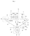
- Fig. 1 is a diagram showing one example of the overall composition of an inkjet recording apparatus of a transfer type.
- the inkjet recording apparatus 10 principally comprises: an intermediate transfer body 12, a treatment liquid deposition unit 14, an ink ejection unit 16, and a transfer unit 18, and it is also provided with a solvent removal unit 20, a cleaning unit 22, and an image fixing unit 24.
- the intermediate transfer body 12 is composed of an endless belt having a prescribed width, and the intermediate transfer body 12 is wound about a plurality of rollers 26. In the present embodiment, an example in which the four rollers 26A to 26D are used is described.
- the intermediate transfer body 12 is not limited to being an endless belt, and it may also employ a method where a cut-sheet intermediate transfer body is conveyed by a conveyor belt, or it may use a drum-shaped member.
- the motive force of a motor (not illustrated) is transmitted to at least one main roller of the plurality of rollers 26, and by the driving of this motor the intermediate transfer body 12 is caused to rotate about the outer side of the rollers 26 (26A to 26D) in the counter-clockwise direction in Fig. 1 (hereinafter, called the "rotational direction of the transfer body").
- a recording head (treatment liquid head) 30S corresponding to the treatment liquid is provided in the treatment liquid deposition unit 14.
- the treatment liquid head 30S ejects treatment liquid from an ejection face which opposes the intermediate transfer body 12. Accordingly, droplets of the treatment liquid are deposited onto the recording surface 12a of the intermediate transfer body 12.
- the treatment liquid deposition unit 14 is not limited to a method which ejects treatment liquid from a head having nozzles, and may also employ an application method which uses an application roller. With this application method, treatment liquid can be applied readily onto virtually the whole surface of the intermediate transfer body 12 including the image region where the ink droplets are deposited. In this case, it is desirable that the thickness of the treatment liquid on the intermediate transfer body 12 should be 1 ⁇ m to 5 ⁇ m.
- the treatment liquid deposition unit 14 is provided before the ink ejection unit 16, but it may also be arranged behind the ink ejection unit 16. Even if the treatment liquid deposition unit 14 is arranged behind the ink ejection section 16, it is possible to obtain similar beneficial effects to a case where the treatment liquid deposition unit 14 is arranged before the ink ejection unit.
- the ink ejection unit 16 is arranged next to the treatment liquid deposition unit 14.
- the ink ejection unit 16 comprises recording heads (ink heads) 30K, 30C, 30M and 30Y which correspond to the respective colors of ink of black (K), cyan (C), magenta (M) and yellow (Y).
- Respective inks which satisfy the ink composition conditions of the present invention are stored in respective ink storage units (not shown) which correspond to the inks of respective colors, and these inks are supplied to the respective recording heads 30K, 30C, 30M and 30Y.
- the ink heads 30K, 30C, 30M and 30Y respectively eject the inks of the corresponding colors, from an ejection surface which opposes the intermediate transfer body 12. Accordingly, the inks of the respective colors are deposited onto the recording surface 12a of the intermediate transfer body 12.
- Each of the treatment liquid head 30S and the ink heads 30K, 30C, 30M and 30Y is a full line head in which a plurality of ejection ports (nozzles) are formed through the maximum recording width of the image formed on the intermediate transfer body 12. Therefore, it is possible to record images at high speed on the intermediate transfer body 12, in comparison with a serial type of head which performs recording while scanning a short shuttle head back and forth in the breadthways direction of the intermediate transfer body 12 (the front to back direction with respect to the plane of the drawing in Fig. 1 ).
- the present invention is also suitable for a serial system which has a relatively high recording speed, for example, a one-pass recording system which forms one line in one scanning action.
- all of the respective recording heads (the treatment liquid head 30S, and the ink heads 30K, 30C, 30M and 30Y) have the same structure, and hereinafter, the reference numeral 30 is used to indicate a representative example of these recording heads.
- the region of the intermediate transfer body 12 on which the treatment liquid has been deposited is moved sequentially to directly below the ink heads 30K, 30C, 30M and 30Y, due to the rotation of the intermediate transfer body 12, and the inks of the corresponding colors are ejected respectively from the ink heads 30K, 30C, 30M and 30Y.
- the treatment liquid deposition volume and the ink deposition volume are adjusted in accordance with requirements. For example, it is possible to change the amount of treatment liquid deposited in accordance with the type of the recording medium to which the image is transferred, in order to adjust the viscosity and other properties of the ink aggregate which is created by the mixing of the treatment liquid and the ink.
- the added amount of the solid component in the emulsion is equal to or greater than 0.05 wt%, by weight ratio, with respect to the solid component in the ink, in order to obtain good separation performance and good adhesive strength inside the ink film. If the added amount is less than 0.05 wt%, then a sufficient separating effect is not obtained. As the added amount of the emulsion gradually increases, the reliability of the ink gradually declines, and therefore it is desirable that the solid component should be restricted to approximately 30 wt% with respect to the total amount of ink.
- the wax used may be carnauba wax, paraffin wax, microcrystalline wax, montan wax, alcohol wax, polyethylene wax, PTFE wax, synthetic acid wax, ⁇ olefin - anhydrous maleic acid copolymer, or the like. Furthermore, it is also possible to form a separating layer by depositing a separating component only, in a separate fashion, before depositing treatment agent.
- the solvent removal unit 20 is arranged on the downstream side of the ink ejection unit 16 in terms of the direction of rotation of the transfer body.
- a solvent removal roller 32 is provided in the solvent removal unit 20 at a position corresponding to the roller 26A via the intermediate transfer body 12.
- the solvent removal roller 32 is made of a roller-shaped porous material, and is arranged so as to abut against the recording surface 12a of the intermediate transfer body 12.
- Other possible modes are, for example, a system which removes excess solvent from the intermediate transfer body 12 by means of an air knife, or a system which evaporates off the solvent by heating. Any solvent removal system may be adopted, but desirably, a system which does not employ heat is used.
- the solvent on the recording surface 12a of the intermediate transfer body 12 is removed by the solvent removal roller 32. Therefore, even in cases where a large amount of the treatment liquid is deposited on the recording surface 12a of the intermediate transfer body 12, since the solvent is removed by the solvent removal unit 20, then a large amount (excessive amount) of solvent (dispersion medium) is not transferred to the recording medium 34 in the transfer unit 18. Consequently, even in a case where paper, or the like, is used as the recording medium 34, there is no occurrence of problems which are characteristic of water-based solvents, such as curling, cockling, or the like.
- the ink aggregate By removing excess solvent from the ink aggregate by means of the solvent removal unit 20, the ink aggregate can be condensed and the internal aggregating force can be raised further. By this means, the coalescence of the resin particles contained in the ink aggregate is promoted effectively, and a stronger internal aggregating force can be imparted to the aggregate before the transfer step is performed. Moreover, it is possible to impart good fixing properties and luster to the image after transfer to the recording medium, due to the effective condensation of the ink aggregate by removal of the solvent.
- the solvent removal unit 20 There is no particular need to remove all of the solvent by the solvent removal unit 20. If the ink aggregate is condensed excessively by removing the solvent excessively, then the aggregating force between the ink aggregate and the transfer body becomes too strong, and therefore a very large pressure is needed for transfer, which is not desirable. Rather, in order to maintain a viscous elasticity which is suitable for transfer, it is desirable to leave a small amount of solvent.
- One of the beneficial effects obtained by leaving a small amount of residual solvent is that since the ink aggregate is hydrophobic, and the non-volatile solvent component (principally, the organic solvent, such as glycerine) is hydrophilic, then the ink aggregate and the residual solvent component separate after carrying out solvent removal, and a thin layer of liquid composed of the residual solvent component is formed between the ink aggregate and the intermediate transfer body. Consequently, the adhesive force of the ink aggregate to the transfer body becomes weak, which is beneficial for improving transfer characteristics.
- the non-volatile solvent component principally, the organic solvent, such as glycerine
- the transfer unit 18 is arranged on the downstream side of the solvent removal roller 20 in terms of the direction of rotation of the transfer body.
- a pressurization and heating roller 36 is provided in the transfer unit 18 at a position which opposes the roller 26B, via the intermediate transfer body 12.
- a heater 37 is provided inside the pressurization and heating roller 36, in such a manner that the temperature of the outer circumferential surface of the pressurization and heating roller 36 is raised by this heater 37.
- the recording medium 34 is conveyed from the left-hand side to the right-hand side in Fig. 1 , so as to pass between the intermediate transfer body 12 and the pressurization and heating roller 36.
- the front surface of the recording medium 34 makes contact with the recording surface 12a of the intermediate transfer body 12, and pressurization and heating is carried out by the pressurization and heating roller 36, from the rear surface of the recording medium 34.
- the surface temperature in the transfer section of the intermediate transfer body 12 is raised to the transfer temperature and the image of dots of ink aggregate formed on the intermediate transfer body 12 is softened to an appropriate softened state.
- the dot image formed on the recording surface 12a of the intermediate transfer body 12 is transferred to the recording medium 34, in this state.
- a desirable structure is one where the heating section is limited only to the transfer section of the intermediate transfer body 12.
- the transfer temperature is the surface temperature of the transfer section of the intermediate transfer body 12, and the surface temperature of the pressurization and heating roller 36 is set to a higher temperature than this transfer temperature, in order to take account of the fact that the intermediate transfer body 12 is heated via the recording medium.
- a recording medium heating device which applies a heating process to the recording medium 34 before the recording medium 34 is conveyed to the transfer unit 18. It is possible to achieve effective thermal conduction during transfer by making the recording medium reach a desired transfer temperature when it makes direct contact with the image of dots of the ink aggregate.
- the ink image is melted immediately upon transfer and enters into the indentations and capillaries of the surface of the recording medium, thereby producing an anchoring effect due to the increased contact surface area.
- this anchoring effect the adhesive force between the recording medium 34 and the ink aggregate is enhanced and transfer is carried out in a satisfactory fashion.
- the heating temperature of the recording medium 34 can be adjusted freely in accordance with the type of recording medium 34.
- indentations in the surface of the paper caused by pulp fibers, as in the case of normal paper, high-grade paper, or the like
- a strong anchoring effect can be expected between the ink image and the surface of the recording medium, and in this case, by adjusting the viscosity of the ink aggregate through controlling the heating temperature of the surface of the recording medium which makes contact during direct transfer, as well as the heating temperature in the heating unit, it is possible to achieve an optimal adhesive force in the ink image and hence to impart good fixing properties of the image to normal paper, high-grade paper, or the like.
- a recording medium 34 having a smooth surface such as coated paper
- the heating temperature is set to a relatively low temperature.
- a recording medium 34 having surface indentations such as high-grade paper
- an air layer is liable to be interposed between the paper and the ink image, and therefore it is desirable to set the heating temperature to a relatively higher temperature, since this can be expected to produce a good anchoring effect due to the increase in the adhesive force of the polymer component.
- a structure having a surface layer which has separating properties is also possible to adopt, on the surface of the intermediate transfer body, a structure having a surface layer which has separating properties, according to requirements. If the surface of the transfer body has been imparted with separating properties, then it has low surface energy and high separating properties, and therefore it is possible to achieve a high transfer rate. In the present invention, it is possible to obtain a satisfactory transfer rate even if separating properties are not imparted in particular, but from the viewpoint of the cleaning load, and the like, there is no particular problem even if separating properties are imparted to the surface of the intermediate transfer body.
- a surface having separating properties as referred to in the present invention means a surface having a critical surface tension of 30 mN/m or less, or an angle of contact with respect to water of 75° or above.
- Desirable materials for use as the surface layer of the intermediate transfer body 12 are, for example, commonly known materials such as: a polyurethane resin, a polyester resin, a polystyrene resin, a polyolefin resin, a polybutadiene resin, a polyamide resin, a polyvinyl chloride resin, a polyethylene resin, a fluorine resin, a polyimide resin, and the like.
- the cleaning unit 22 is arranged on the downstream side of the transfer unit 18 in terms of the direction of rotation of the transfer body and to the upstream side of the treatment agent deposition unit 14 in terms of the direction of rotation of the transfer body.
- a cleaning roller 38 is provided in the cleaning unit 22 at a position opposing the roller 26C via the intermediate transfer body 12, being disposed so as to abut the recording surface 12a of the intermediate transfer body 12, and the cleaning roller 38 removes the residual material from the recording surface 12a of the intermediate transfer body 12 after transfer.
- Possible modes of the cleaning roller 38 are: a system where the cleaning roller 38 is made of a soft and porous member, and cleans the surface of the intermediate transfer body (recording surface 12a) while being impregnated with a cleaning liquid by means of a cleaning liquid application device; a system where a brush is provided on the surface of the roller and dirt on the surface of the intermediate transfer body is removed by the brush while applying cleaning liquid to the surface of the intermediate transfer body; or a system where a flexible blade is provided on the roller surface and the residual material on the surface of the intermediate transfer body (the residual traces of the ink aggregate) are swept away by this blade; or the like.
- the linear speed of the surface of the cleaning roller 38 is set so as to be slower or faster than the linear speed of the surface of the intermediate transfer body, rather than being equal to same, then it is possible to enhance the rate of removing the residual material.
- a shearing force is generated on the surface of the intermediate transfer body in accordance with the speed differential between the surface of the cleaning roller 38 and the surface of the intermediate transfer body, and therefore the residual material can be removed efficiently.
- an image fixing unit 24 is provided in order to impart stronger fixing properties to the recording medium after transfer.
- the image fixing unit 24 is disposed on the recording medium output side of the transfer unit 18 (the right-hand side in Fig. 1 ).
- two fixing rollers 40A and 40B are provided on the front and rear surfaces of the recording medium 34, and by pressurizing and heating the image transferred to and formed on the recording medium 34 by the fixing rollers 40A and 40B, it is possible to improve the fixing properties of the recorded image on the recording medium 34.
- the fixing rollers 40A and 40B are a pair of rollers which consist of one pressurizing and heating roller and one heating roller, but the fixing rollers 40A and 40B are not limited to these.
- the recording medium 34 is normal paper, high-grade paper, or the like
- a strong anchoring effect can be expected between the ink aggregate and the surface of the recording medium, and in this case, by adjusting the viscosity of the ink aggregate through controlling the heating temperature of the surface of the medium which makes contact during direct transfer, as well as the heating temperature in the heating unit, it is possible to achieve an optimal viscosity of the ink aggregate and hence to impart good fixing properties of the image to normal paper, high-grade paper, or the like.
- the treatment liquid is deposited on the intermediate transfer body 12 by means of the treatment liquid deposition unit 14 (step 1).
- the treatment liquid may be applied in the form of a thin film onto the intermediate transfer body 12 by means of an application roller instead of the treatment liquid deposition unit 14.
- the intermediate transfer body 12 onto which the treatment liquid has been deposited is conveyed so as to be positioned under the recording head 16 by the belt conveyor and the ink according to the present invention is ejected as droplets and thereby made to contact the treatment liquid (step 2).
- the ink according to the present invention is ejected as droplets and thereby made to contact the treatment liquid (step 2).
- an ink image formed of the ink aggregate is created by mixing the treatment liquid and the ink together.
- the intermediate transfer body 12 on which the ink image has been formed is conveyed by the belt conveyor toward the solvent removal unit 20, and the solvent on the recording surface 12a of the intermediate transfer body 12 is removed by the solvent removal roller 32 (step 3).
- the intermediate transfer body 12 from which the solvent has been removed is conveyed by a belt conveyor toward the transfer unit 18.
- the recording medium 34 is also conveyed to the transfer unit 18 via a separate route, and the recording medium 34 is interposed between the intermediate transfer body 12 and the pressurization and heating roller 36 (which includes a heater).
- the surface temperature in the transfer portion of the intermediate transfer body 12 is raised to the transfer temperature (for example, 100°C), and the ink aggregate formed on the intermediate transfer body 12 is transferred to the recording medium 34 in a suitably softened state (step 4).
- the recording medium onto which the ink aggregate has been transferred is conveyed to the image fixing unit 24 and is subjected to a heat treatment process at a temperature equal to or greater than the softening point of the polymer micro-particles in the ink composition, thereby making it possible to fix the ink aggregate onto the recording medium with a suitable image strength (Step 5).
- the intermediate transfer body 12 which has completed the transfer process is circulated back to the position of the treatment liquid deposition unit 14 via the cleaning unit 22, and the operations of the above-described steps 1 to 5 are repeated.
- Fig. 2 is a general schematic drawing of an inkjet recording apparatus of a direct recording type.
- the image recording apparatus 100 shown in Fig. 2 employs a direct recording method in which an image is formed directly onto a recording medium 122.
- the inkjet recording apparatus 100 comprises: a treatment liquid deposition unit 138 which deposits treatment liquid onto a recording medium 122; an ink ejection unit 112 comprising heads 112K, 112C, 112M and 112Y which eject droplets of inks of respective colors of K, C, M and Y onto the recording medium 122 on which a treatment liquid layer has been formed by depositing treatment liquid; a solvent removal unit 118 comprising a hot air supply apparatus 118A and a heating panel 118B which remove residual solvent component that is remaining on the recording medium 122 onto which droplets of the inks of respective colors of K, C, M and Y have been ejected; and an image fixing unit 123 comprising fixing rollers 123A and 123B which heats the image formed on the recording medium 122 and fixes the image to the recording medium 112.
- the recording medium 122 which is output from the paper supply unit (not illustrated) is supplied to a suction belt conveyance unit 140.
- the suction belt conveyance unit 140 has a structure in which an endless belt 146 is wound between rollers 142 and 144, and at least the portion of the belt which opposes the treatment liquid deposition unit 138, the ink ejection unit 112, the solvent removal unit 118 and the image fixing unit 123 is composed so as to form a horizontal surface (flat surface).
- the belt 146 has a greater width than the recording medium 122, and a plurality of suction apertures (not illustrated) are formed in the belt surface.
- a suction chamber (not illustrated) is provided on the inner side of the belt 146 which is wound about the rollers 142 and 144, at a position opposing the treatment liquid deposition unit 138, the ink ejection unit 112, the solvent removal unit 118 and the image fixing unit 123.
- the recording medium 122 is suctioned and held on the belt 146 by creating a negative pressure by suctioning the suction chamber with a pump (not illustrated).
- the belt 146 By transmitting the motive force of a motor (not illustrated in Fig. 2 ) to at least one of the rollers 142, 144 about which the belt 146 is wound, the belt 146 is driven in a counterclockwise direction in Fig. 2 , and the recording medium 122 held on the belt 146 is conveyed from right to left in Fig. 2 .
- a motor not illustrated in Fig. 2
- a belt cleaning unit (not illustrated) is disposed in a predetermined position (a suitable position outside the printing area) on the exterior side of the belt 146.
- a cleaning roller such as a brush roller and a water absorbent roller
- an air blow configuration in which clean air is blown onto the belt, or a combination of these.
- a mode can also be envisaged in which a roller and nip conveyance mechanism is used instead of the suction belt conveyance unit 140, but this is problematic because if the print region is conveyed by a roller and nip mechanism, the roller makes contact with the printing surface of the paper immediately after printing and therefore the image is liable to be smudged. Consequently, it is desirable to employ suction belt conveyance which does not make contact with the image surface in the printing region, as in the present embodiment.
- compositions including an application roller or to employ an inkjet head as the treatment liquid deposition unit 138.
- the solvent in the ink composition is removed by the solvent removal unit 118 which is provided to the downstream side of the ink ejection section 112.
- the solvent is removed by being heated by the hot air flow generated by the hot air supply apparatus 118A from the upper surface of the applied film, and by the heating panel 118B which is provided on the opposite side of the recording medium 122 from the applied film.
- the present invention is not limited to these examples, and it is also possible to remove the solvent by means of a solvent removal roller or a heating roller.
- the image fixing unit 123 is fixed onto the recording medium 122 by heating and pressurizing the ink droplets which have been ejected onto the recording medium 122. It is also possible to adopt a composition similar to that of the first embodiment for the image fixing unit. Furthermore, in a similar fashion, the heating conditions are set to a temperature equal to or higher than the softening point of the polymer micro-particles contained in the ink composition.
- the constituent elements which are omitted from the illustration in Fig. 2 include: a decurling unit which removes curl in the recording medium 122 supplied form the paper supply unit; a cutter which cuts the recording medium to a prescribed size if a long recording medium (roll-shaped recording medium) is used, and the like.
- the inkjet recording apparatus 100 shown in Fig. 2 has particularly beneficial effects when using a medium having non-permeable properties (non-permeable medium) as the recording medium 122 with respect to the treatment liquid and ink.
- a medium having non-permeable medium there are coated paper, resin films, such as OHP film, metal sheet, and the like.
- the applicability of the recording medium 122 is not limited to a medium having non-permeable properties, and it is also possible to use a medium having poor permeability compared to a medium having permeable properties, such as normal paper.
- a solution comprising 6 parts by weight of styrene, 11 parts by weight of stearyl methacrylate, 4 parts by weight of styrene macromer AS-6 (made by Toa Gosei), 5 parts by weight of "Premmer” PP-500 (made by NOF Corp.), 5 parts by weight of methacrylic acid, 0.05 parts by weight of 2-mercapto ethanol, and 24 parts by weight of methylethyl ketone was prepared in a reaction vessel.
- a mixed solution was prepared by introducing, into a titration funnel, 14 parts by weight of styrene, 24 parts by weight of stearyl methacrylate, 9 parts by weight of styrene macromer AS-6 (made by Toa Gosei), 9 parts by weight of "Premmer” PP-500 (made by NOF Corp.), 10 parts by weight of methacrylic acid, 0.13 parts by weight of 2-mercapotoethanol, 56 parts by weight of methylethyl ketone, and 1.2 parts by weight of 2,2' - azobis(2,4 - dimethyl valeronitrile).
- the mixed solution inside the reaction vessel was raised to a temperature of 75°C while being agitated in a nitrogen atmosphere, and the mixed solution in the titration funnel was gradually added by titration over a period of one hour.
- a solution obtained by dissolving 1.2 parts by weight of 2,2' - azobis (2,4 - dimethyl valeronitrile) in 12 parts by weight of methylethyl ketone was added by titration over a period of 3 hours, and the mixture was matured for a further two hours at 75°C and two hours at 80°C, thereby yielding a polymer dispersant solution.
- a portion of the polymer dispersant solution thus obtained was separated by removing the solvent, and the resulting solid component was diluted to 0.1 wt% with tetrahydrofuran, and then measured with a high-speed GPC (gel permeation chromatography) apparatus HLC-8220GPC, using three sequential columns : TSKgel Super HZM-H, TSKgel Super HZ4000, TSKgel Super HZ2000.
- the weight-average molecular weight was 25,000 when indicated as the weight of a polystyrene molecule.
- a cyan pigment dispersion liquid B (particle diameter 103 nm) having differentiated pigment particle diameter was obtained by adjusting the dispersion conditions such as the rotational speed of the disperser or the dispersion processing time.
- the solid concentration of the polymer micro-particles thus obtained was 39.2% (solid yield rate 97.0%).
- the average particle diameter was measured to be 73 nm by diluting the obtained polymer micro-particles to a suitable concentration for measurement and then measuring with a sub-micron particle analyzer N4 (made by Beckman Coulter (Inc.)).
- the polymer micro-particles 1 to 6 and 8 to 13 having respective physical properties, such as particle diameter, Tg, viscoelasticity characteristics, and so on, were synthesized by altering the monomer composition, the amount of initiator, or the amount of surfactant used, or by adding a chain transfer agent.
- Fig. 3 is a table showing the compositions and properties of the polymer micro-particles 1-13.
- the polymer particles 1-13 have the following general formula.
- composition ratio means the composition ratio among Styrene block (St), Butyl Acrylate block (BA) and Acrylic Acid block (AA) in the above general formula.
- the polymer micro-particles 14 and 15 having a more monodisperse particle diameter distribution were obtained from the polymer micro-particles 6 and 8 by adjusting the Mv/Mn value of the liquid dispersion of the polymer micro-particles, by means of the rotational speed and operating time in cases where a centrifugal sedimentation method was used to filter the large and coarse particles after manufacturing the liquid dispersion of polymer micro-particles, and by means of the filter pore size and number of filtering steps using an acetyl cellulose membrane filter in cases where a microfiltration method was used.
- Ink compositions 1-20 were created according to the compositional ratio stated below, by mixing a pigment dispersion liquid and a liquid dispersion of polymer micro-particles obtained as described above. After mixing the respective components, the large and coarse particles were removed by using a 5 ⁇ m filter to produce an ink composition. By this means, the ink compositions 1-20 were obtained.
- Fig. 4 is a table of the correspondences between the polymer micro-particles 1-15 used and the ink compositions 1-20 obtained.
- compositional ratio of ink compositions 1- 20 Pigment Blue 15:3 4 wt% Polymer micro-particles (Polymer micro-particles 1-15) 8 wt% Glycerine 20 wt% Diethylene glycol 10 wt% Olefin E1010 (made by Nisshin Kagaku Kogyo) 1 wt% Deionized water remainder
- a treatment liquid was prepared by means of the following method.
- the surface tension was regulated by adjusting the addition and the added amount of fluorine-based surfactant.
- compositional ratio of treatment liquid Glycerine 12.5 wt% Diethylene glycol 10 wt% Phosphoric acid 5 wt% Olefin E1010 1.5 wt% Deionized water remainder
- a solid image for evaluation was formed by ejecting droplets of the evaluation ink at a droplet ejection resolution of 1200 x 1200 dpi and a droplet ejection volume of 3.5 pl onto an intermediate transfer body to which a treatment liquid had been applied. Silicone rubber was used for the intermediate transfer body. The solvent was removed by blowing heated air at a temperature of 80°C. The image was then transferred onto Tokubishi art paper made by Mitsubishi Paper Mills Co., Ltd. at a transfer temperature of 90°C. A heating and fixing process was carried out by passing the transferred image through a fixing roller set to a heating temperature of 90°C. If the softening point of the polymer was 90°C or higher, then the heating temperature was set to be 10°C higher than the softening point. The conveyance speed was 500 mm/s.
- a solid image for evaluation was formed by ejecting droplets of the evaluation ink at a droplet ejection resolution of 1200 x 1200 dpi and a droplet ejection volume of 3.5 pl onto Tokubishi art paper. If treatment liquid was deposited, then this treatment liquid was deposited by droplet ejection onto the Tokubishi art paper, in a similar fashion to the ink, before ejecting the ink. The solvent was removed by blowing heated air at a temperature of 80°C. Thereupon, a heating and fixing process is carried out by passing the paper through a fixing roller set to a heating temperature of 90°C.
- the heating temperature was set to be 10°C higher than the softening point.
- the conveyance speed was 500 mm/s.
- the results are shown in Figs. 5-7 .
- the image deformation and fixing properties in Figs. 5-7 were evaluated on the basis of the following criteria.
- Figs. 8A to 8D show the criteria of the evaluations of image quality after transfer.
Landscapes
- Chemical & Material Sciences (AREA)
- Engineering & Computer Science (AREA)
- Life Sciences & Earth Sciences (AREA)
- Materials Engineering (AREA)
- Wood Science & Technology (AREA)
- Organic Chemistry (AREA)
- General Engineering & Computer Science (AREA)
- Ink Jet Recording Methods And Recording Media Thereof (AREA)
- Inks, Pencil-Leads, Or Crayons (AREA)
- Ink Jet (AREA)
Applications Claiming Priority (1)
| Application Number | Priority Date | Filing Date | Title |
|---|---|---|---|
| JP2007256770A JP2009083324A (ja) | 2007-09-28 | 2007-09-28 | インクジェット記録方法 |
Publications (2)
| Publication Number | Publication Date |
|---|---|
| EP2042318A1 true EP2042318A1 (fr) | 2009-04-01 |
| EP2042318B1 EP2042318B1 (fr) | 2011-02-09 |
Family
ID=40193672
Family Applications (1)
| Application Number | Title | Priority Date | Filing Date |
|---|---|---|---|
| EP20080165234 Ceased EP2042318B1 (fr) | 2007-09-28 | 2008-09-26 | Procédé d'impression par jet d'encre |
Country Status (5)
| Country | Link |
|---|---|
| US (1) | US20090087565A1 (fr) |
| EP (1) | EP2042318B1 (fr) |
| JP (1) | JP2009083324A (fr) |
| CN (1) | CN101396910B (fr) |
| DE (1) | DE602008004864D1 (fr) |
Cited By (5)
| Publication number | Priority date | Publication date | Assignee | Title |
|---|---|---|---|---|
| FR2990156A1 (fr) * | 2012-05-07 | 2013-11-08 | Mgi France | Groupe, systeme et procede de transfert numerique de matiere visqueuse |
| US10357963B2 (en) | 2012-03-05 | 2019-07-23 | Landa Corporation Ltd. | Digital printing process |
| US10357985B2 (en) | 2012-03-05 | 2019-07-23 | Landa Corporation Ltd. | Printing system |
| US10427399B2 (en) | 2015-04-14 | 2019-10-01 | Landa Corporation Ltd. | Apparatus for threading an intermediate transfer member of a printing system |
| US10434761B2 (en) | 2012-03-05 | 2019-10-08 | Landa Corporation Ltd. | Digital printing process |
Families Citing this family (52)
| Publication number | Priority date | Publication date | Assignee | Title |
|---|---|---|---|---|
| JP5776141B2 (ja) * | 2009-06-23 | 2015-09-09 | 株式会社リコー | インクジェット記録用インク、並びに、該インクを用いたインクジェット記録方法、該インクを収容したカートリッジ、及び記録物 |
| JP5518397B2 (ja) * | 2009-08-12 | 2014-06-11 | 富士フイルム株式会社 | 水性インク組成物、複合粒子の製造方法、インクセット、及び、画像形成方法 |
| JP5523884B2 (ja) * | 2010-03-18 | 2014-06-18 | 富士フイルム株式会社 | インク組成物、インクセットおよびインクジェット画像形成方法 |
| US10632740B2 (en) | 2010-04-23 | 2020-04-28 | Landa Corporation Ltd. | Digital printing process |
| US8827436B2 (en) | 2010-05-27 | 2014-09-09 | E I Du Pont De Nemours And Company | Fixer inks for use with ink jet inks |
| JP5606818B2 (ja) * | 2010-07-27 | 2014-10-15 | 富士フイルム株式会社 | インク組成物、インクセットおよび画像形成方法 |
| JP5725808B2 (ja) | 2010-11-18 | 2015-05-27 | キヤノン株式会社 | 転写型インクジェット記録方法 |
| JP2012185267A (ja) * | 2011-03-04 | 2012-09-27 | Oki Data Corp | ベルト装置、転写ユニットおよび画像形成装置 |
| US10569534B2 (en) | 2012-03-05 | 2020-02-25 | Landa Corporation Ltd. | Digital printing system |
| US10642198B2 (en) | 2012-03-05 | 2020-05-05 | Landa Corporation Ltd. | Intermediate transfer members for use with indirect printing systems and protonatable intermediate transfer members for use with indirect printing systems |
| US9902147B2 (en) | 2012-03-05 | 2018-02-27 | Landa Corporation Ltd. | Digital printing system |
| US10190012B2 (en) | 2012-03-05 | 2019-01-29 | Landa Corporation Ltd. | Treatment of release layer and inkjet ink formulations |
| EP2822776B1 (fr) | 2012-03-05 | 2018-08-01 | Landa Corporation Ltd. | Procédé d'impression par transfert |
| DE202013012736U1 (de) | 2012-03-05 | 2018-12-20 | Landa Corporation Ltd. | Tintenfilmkonstruktionen |
| US9498946B2 (en) | 2012-03-05 | 2016-11-22 | Landa Corporation Ltd. | Apparatus and method for control or monitoring of a printing system |
| WO2015036960A1 (fr) | 2013-09-11 | 2015-03-19 | Landa Corporation Ltd. | Formulation pour traitement de couche de transfert |
| BR112014021786B1 (pt) | 2012-03-05 | 2021-06-08 | Landa Corporation Ltd | estruturas de película de tinta |
| US9517618B2 (en) | 2012-03-15 | 2016-12-13 | Landa Corporation Ltd. | Endless flexible belt for a printing system |
| US9145022B2 (en) * | 2012-06-20 | 2015-09-29 | Canon Kabushiki Kaisha | Image recording method |
| JP6166048B2 (ja) * | 2013-01-21 | 2017-07-19 | 株式会社ミマキエンジニアリング | インクジェットプリンタ及び印刷方法 |
| GB201401173D0 (en) | 2013-09-11 | 2014-03-12 | Landa Corp Ltd | Ink formulations and film constructions thereof |
| JP6264860B2 (ja) * | 2013-11-27 | 2018-01-24 | セイコーエプソン株式会社 | 記録装置 |
| GB2536489B (en) | 2015-03-20 | 2018-08-29 | Landa Corporation Ltd | Indirect printing system |
| JP6840552B2 (ja) * | 2016-01-29 | 2021-03-10 | キヤノン株式会社 | インクジェット記録方法及びインクジェット記録装置 |
| JP2017149042A (ja) * | 2016-02-25 | 2017-08-31 | セイコーエプソン株式会社 | 画像形成装置、画像形成方法 |
| JP2017190370A (ja) * | 2016-04-11 | 2017-10-19 | セイコーエプソン株式会社 | インクジェットインク組成物、及び捺染方法 |
| GB201609463D0 (en) | 2016-05-30 | 2016-07-13 | Landa Labs 2012 Ltd | Method of manufacturing a multi-layer article |
| DE112017002714T5 (de) | 2016-05-30 | 2019-02-28 | Landa Corporation Ltd. | Digitales Druckverfahren |
| CN109312529A (zh) * | 2016-05-30 | 2019-02-05 | 佳能株式会社 | 多孔体带及其生产方法、和喷墨记录设备 |
| JP2017218485A (ja) * | 2016-06-06 | 2017-12-14 | 株式会社リコー | インク用樹脂粒子、インク、インク収容容器、インクジェット記録方法、インクジェット記録装置及び記録物 |
| US20180273761A1 (en) * | 2017-03-24 | 2018-09-27 | Fuji Xerox Co., Ltd. | Pigment dispersant, aqueous pigment dispersion composition, and aqueous ink |
| ES2927206T3 (es) | 2017-04-28 | 2022-11-03 | ACTEGA Schmid Rhyner AG | Dispositivo y procedimiento para la generación de un revestimiento texturizado |
| JP2019003850A (ja) * | 2017-06-16 | 2019-01-10 | トヨタ自動車株式会社 | 触媒層の製造方法およびその製造装置 |
| JP2019014244A (ja) * | 2017-07-04 | 2019-01-31 | キヤノン株式会社 | インクジェット記録方法、及び、インクジェット記録装置 |
| CN111212736B (zh) | 2017-10-19 | 2021-11-23 | 兰达公司 | 用于打印系统的环形柔性带 |
| WO2019097464A1 (fr) | 2017-11-19 | 2019-05-23 | Landa Corporation Ltd. | Système d'impression numérique |
| US11511536B2 (en) | 2017-11-27 | 2022-11-29 | Landa Corporation Ltd. | Calibration of runout error in a digital printing system |
| US11707943B2 (en) | 2017-12-06 | 2023-07-25 | Landa Corporation Ltd. | Method and apparatus for digital printing |
| US11679615B2 (en) | 2017-12-07 | 2023-06-20 | Landa Corporation Ltd. | Digital printing process and method |
| JP2019130780A (ja) * | 2018-01-31 | 2019-08-08 | コニカミノルタ株式会社 | インクジェット記録装置 |
| IL279556B2 (en) | 2018-06-26 | 2024-06-01 | Landa Corp Ltd | Part for intermediate transfer to a digital printing system |
| US10994528B1 (en) | 2018-08-02 | 2021-05-04 | Landa Corporation Ltd. | Digital printing system with flexible intermediate transfer member |
| US12001902B2 (en) | 2018-08-13 | 2024-06-04 | Landa Corporation Ltd. | Correcting distortions in digital printing by implanting dummy pixels in a digital image |
| US11318734B2 (en) | 2018-10-08 | 2022-05-03 | Landa Corporation Ltd. | Friction reduction means for printing systems and method |
| CN113272144B (zh) | 2018-12-24 | 2023-04-04 | 兰达公司 | 数字印刷系统和方法 |
| JP7255282B2 (ja) * | 2019-03-27 | 2023-04-11 | コニカミノルタ株式会社 | 画像形成方法、プログラムおよび画像形成装置 |
| WO2020202145A1 (fr) | 2019-03-31 | 2020-10-08 | Landa Corporation Ltd | Systèmes et procédés pour empêcher ou minimiser les défauts d'impression dans les processus d'impression |
| JP7275812B2 (ja) * | 2019-04-25 | 2023-05-18 | セイコーエプソン株式会社 | 水系インクジェットインク組成物、及びインクジェット記録方法 |
| WO2021105806A1 (fr) | 2019-11-25 | 2021-06-03 | Landa Corporation Ltd. | Séchage d'encre en impression numérique avec un rayonnement infrarouge absorbé par des particules incorporées à l'intérieur d'un itm |
| US11321028B2 (en) | 2019-12-11 | 2022-05-03 | Landa Corporation Ltd. | Correcting registration errors in digital printing |
| CN114868087A (zh) | 2019-12-29 | 2022-08-05 | 兰达公司 | 印刷方法和系统 |
| JP2024506561A (ja) | 2021-02-02 | 2024-02-14 | ランダ コーポレイション リミテッド | 印刷画像における歪みの軽減 |
Citations (2)
| Publication number | Priority date | Publication date | Assignee | Title |
|---|---|---|---|---|
| EP0606490A1 (fr) | 1992-07-02 | 1994-07-20 | Seiko Epson Corporation | Procede d'impression par jet d'encre du type a transfert intermediaire |
| EP1770131A1 (fr) * | 2005-09-30 | 2007-04-04 | FUJIFILM Corporation | Composition d'encre pour enregistrement par jet d'encre et procédé de production d'une plaque d'impression planographique utilisant cette encre |
Family Cites Families (11)
| Publication number | Priority date | Publication date | Assignee | Title |
|---|---|---|---|---|
| JPS626919A (ja) * | 1986-06-20 | 1987-01-13 | Agency Of Ind Science & Technol | 高強度、高モジユラスピツチ系炭素繊維 |
| US5621022A (en) * | 1992-11-25 | 1997-04-15 | Tektronix, Inc. | Use of polymeric dyes in hot melt ink jet inks |
| JP3367151B2 (ja) * | 1993-07-23 | 2003-01-14 | セイコーエプソン株式会社 | インクジェット記録方法 |
| US6147139A (en) * | 1998-08-31 | 2000-11-14 | Eastman Kodak Company | Inks containing heat fusible particles and method for use |
| US6184268B1 (en) * | 1999-08-30 | 2001-02-06 | Xerox Corporation | Ink jet ink compositions and processes thereof |
| JP2002030235A (ja) * | 2000-07-14 | 2002-01-31 | Konica Corp | インクジェット用水性顔料インクセットおよびインクジェット記録方法 |
| JP2002166533A (ja) * | 2000-11-30 | 2002-06-11 | Konica Corp | 画像形成方法 |
| EP1415671A1 (fr) * | 2002-11-01 | 2004-05-06 | Polyganics B.V. | Drains biodégradables pour applications médicales |
| JP4657932B2 (ja) * | 2005-03-16 | 2011-03-23 | 株式会社リコー | 静電荷像現像用トナー |
| JP2008003360A (ja) * | 2006-06-23 | 2008-01-10 | Ricoh Co Ltd | 静電荷像現像用トナー |
| JP5655776B2 (ja) * | 2010-01-29 | 2015-01-21 | 東レ株式会社 | 電子放出源用ペースト、これを用いた電子放出源および電子放出素子ならびにこれらの製造方法 |
-
2007
- 2007-09-28 JP JP2007256770A patent/JP2009083324A/ja active Pending
-
2008
- 2008-09-26 EP EP20080165234 patent/EP2042318B1/fr not_active Ceased
- 2008-09-26 US US12/239,663 patent/US20090087565A1/en not_active Abandoned
- 2008-09-26 DE DE200860004864 patent/DE602008004864D1/de active Active
- 2008-09-28 CN CN2008101681349A patent/CN101396910B/zh not_active Expired - Fee Related
Patent Citations (2)
| Publication number | Priority date | Publication date | Assignee | Title |
|---|---|---|---|---|
| EP0606490A1 (fr) | 1992-07-02 | 1994-07-20 | Seiko Epson Corporation | Procede d'impression par jet d'encre du type a transfert intermediaire |
| EP1770131A1 (fr) * | 2005-09-30 | 2007-04-04 | FUJIFILM Corporation | Composition d'encre pour enregistrement par jet d'encre et procédé de production d'une plaque d'impression planographique utilisant cette encre |
Cited By (5)
| Publication number | Priority date | Publication date | Assignee | Title |
|---|---|---|---|---|
| US10357963B2 (en) | 2012-03-05 | 2019-07-23 | Landa Corporation Ltd. | Digital printing process |
| US10357985B2 (en) | 2012-03-05 | 2019-07-23 | Landa Corporation Ltd. | Printing system |
| US10434761B2 (en) | 2012-03-05 | 2019-10-08 | Landa Corporation Ltd. | Digital printing process |
| FR2990156A1 (fr) * | 2012-05-07 | 2013-11-08 | Mgi France | Groupe, systeme et procede de transfert numerique de matiere visqueuse |
| US10427399B2 (en) | 2015-04-14 | 2019-10-01 | Landa Corporation Ltd. | Apparatus for threading an intermediate transfer member of a printing system |
Also Published As
| Publication number | Publication date |
|---|---|
| CN101396910A (zh) | 2009-04-01 |
| CN101396910B (zh) | 2012-05-23 |
| EP2042318B1 (fr) | 2011-02-09 |
| DE602008004864D1 (de) | 2011-03-24 |
| JP2009083324A (ja) | 2009-04-23 |
| US20090087565A1 (en) | 2009-04-02 |
Similar Documents
| Publication | Publication Date | Title |
|---|---|---|
| EP2042318B1 (fr) | Procédé d'impression par jet d'encre | |
| JP5085893B2 (ja) | 画像形成装置及びインクセット | |
| JP4908117B2 (ja) | インクセット及び画像形成装置並びにその方法 | |
| US7281790B2 (en) | Ink-jet recording method and ink-jet recording apparatus | |
| JP5599762B2 (ja) | インク組成物、インクセット、及び画像形成方法 | |
| JP2008255135A (ja) | インク及び画像形成方法並びにその装置 | |
| JP2009045851A (ja) | 画像形成方法及び装置 | |
| JP2009083314A (ja) | 画像形成方法及びインクジェット記録装置 | |
| JP2015044408A (ja) | 画像形成方法 | |
| JP2009045794A (ja) | 画像形成方法及び画像形成装置 | |
| JP2001341407A (ja) | 画像形成方法 | |
| JP2010222420A (ja) | インクジェット記録用インク組成物及びインクジェット記録方法 | |
| JP2004090596A (ja) | 画像形成方法及び画像形成装置 | |
| JP6492487B2 (ja) | 画像記録装置 | |
| US20170282533A1 (en) | Auxiliary liquid, liquid set, image recording method and image recording apparatus | |
| JP3624014B2 (ja) | 液体組成物、インクセット及びこれを用いた画像形成方法と画像形成装置 | |
| JP2010142965A (ja) | 画像形成方法 | |
| JP2009119723A (ja) | インクジェット画像形成方法および形成装置 | |
| JPWO2018180284A1 (ja) | インクジェット記録用水性インク組成物、画像形成方法及び樹脂微粒子 | |
| JP5513839B2 (ja) | 画像形成方法 | |
| JP3880082B2 (ja) | インクジェット記録方法及びインクセット | |
| JP2013202956A (ja) | 画像形成方法 | |
| JP2009083315A (ja) | 画像形成方法及び画像形成装置 | |
| JPH0892513A (ja) | カラーインクジェットインク及び記録方法 | |
| JPH0880664A (ja) | 液体組成物、インクセット、及びこれらを用いた画像形成方法と装置 |
Legal Events
| Date | Code | Title | Description |
|---|---|---|---|
| PUAI | Public reference made under article 153(3) epc to a published international application that has entered the european phase |
Free format text: ORIGINAL CODE: 0009012 |
|
| AK | Designated contracting states |
Kind code of ref document: A1 Designated state(s): AT BE BG CH CY CZ DE DK EE ES FI FR GB GR HR HU IE IS IT LI LT LU LV MC MT NL NO PL PT RO SE SI SK TR |
|
| AX | Request for extension of the european patent |
Extension state: AL BA MK RS |
|
| 17P | Request for examination filed |
Effective date: 20090312 |
|
| 17Q | First examination report despatched |
Effective date: 20090508 |
|
| AKX | Designation fees paid |
Designated state(s): DE FR GB |
|
| GRAP | Despatch of communication of intention to grant a patent |
Free format text: ORIGINAL CODE: EPIDOSNIGR1 |
|
| GRAS | Grant fee paid |
Free format text: ORIGINAL CODE: EPIDOSNIGR3 |
|
| GRAA | (expected) grant |
Free format text: ORIGINAL CODE: 0009210 |
|
| AK | Designated contracting states |
Kind code of ref document: B1 Designated state(s): DE FR GB |
|
| REG | Reference to a national code |
Ref country code: GB Ref legal event code: FG4D |
|
| REF | Corresponds to: |
Ref document number: 602008004864 Country of ref document: DE Date of ref document: 20110324 Kind code of ref document: P |
|
| REG | Reference to a national code |
Ref country code: DE Ref legal event code: R096 Ref document number: 602008004864 Country of ref document: DE Effective date: 20110324 |
|
| PLBE | No opposition filed within time limit |
Free format text: ORIGINAL CODE: 0009261 |
|
| STAA | Information on the status of an ep patent application or granted ep patent |
Free format text: STATUS: NO OPPOSITION FILED WITHIN TIME LIMIT |
|
| 26N | No opposition filed |
Effective date: 20111110 |
|
| REG | Reference to a national code |
Ref country code: DE Ref legal event code: R097 Ref document number: 602008004864 Country of ref document: DE Effective date: 20111110 |
|
| REG | Reference to a national code |
Ref country code: FR Ref legal event code: PLFP Year of fee payment: 9 |
|
| REG | Reference to a national code |
Ref country code: FR Ref legal event code: PLFP Year of fee payment: 10 |
|
| REG | Reference to a national code |
Ref country code: FR Ref legal event code: PLFP Year of fee payment: 11 |
|
| PGFP | Annual fee paid to national office [announced via postgrant information from national office to epo] |
Ref country code: FR Payment date: 20200812 Year of fee payment: 13 Ref country code: GB Payment date: 20200916 Year of fee payment: 13 Ref country code: DE Payment date: 20200916 Year of fee payment: 13 |
|
| REG | Reference to a national code |
Ref country code: DE Ref legal event code: R119 Ref document number: 602008004864 Country of ref document: DE |
|
| GBPC | Gb: european patent ceased through non-payment of renewal fee |
Effective date: 20210926 |
|
| PG25 | Lapsed in a contracting state [announced via postgrant information from national office to epo] |
Ref country code: GB Free format text: LAPSE BECAUSE OF NON-PAYMENT OF DUE FEES Effective date: 20210926 Ref country code: FR Free format text: LAPSE BECAUSE OF NON-PAYMENT OF DUE FEES Effective date: 20210930 Ref country code: DE Free format text: LAPSE BECAUSE OF NON-PAYMENT OF DUE FEES Effective date: 20220401 |