EP2042330A2 - Appareil d'enregistrement à jet d'encre - Google Patents
Appareil d'enregistrement à jet d'encre Download PDFInfo
- Publication number
- EP2042330A2 EP2042330A2 EP08017034A EP08017034A EP2042330A2 EP 2042330 A2 EP2042330 A2 EP 2042330A2 EP 08017034 A EP08017034 A EP 08017034A EP 08017034 A EP08017034 A EP 08017034A EP 2042330 A2 EP2042330 A2 EP 2042330A2
- Authority
- EP
- European Patent Office
- Prior art keywords
- ink
- recording medium
- recording
- jet
- image
- Prior art date
- Legal status (The legal status is an assumption and is not a legal conclusion. Google has not performed a legal analysis and makes no representation as to the accuracy of the status listed.)
- Granted
Links
- OAICVXFJPJFONN-UHFFFAOYSA-N Phosphorus Chemical compound [P] OAICVXFJPJFONN-UHFFFAOYSA-N 0.000 claims abstract description 42
- 239000000976 ink Substances 0.000 claims description 255
- 239000007788 liquid Substances 0.000 claims description 196
- 239000003086 colorant Substances 0.000 claims description 24
- 238000011144 upstream manufacturing Methods 0.000 claims description 13
- QSHDDOUJBYECFT-UHFFFAOYSA-N mercury Chemical compound [Hg] QSHDDOUJBYECFT-UHFFFAOYSA-N 0.000 claims description 11
- 238000002834 transmittance Methods 0.000 claims description 11
- 229910001507 metal halide Inorganic materials 0.000 claims description 8
- 150000005309 metal halides Chemical class 0.000 claims description 8
- 230000032258 transport Effects 0.000 description 109
- 238000001723 curing Methods 0.000 description 92
- 238000009281 ultraviolet germicidal irradiation Methods 0.000 description 82
- 239000011248 coating agent Substances 0.000 description 63
- 238000000576 coating method Methods 0.000 description 63
- 230000007246 mechanism Effects 0.000 description 20
- 238000001816 cooling Methods 0.000 description 17
- 238000000151 deposition Methods 0.000 description 16
- 239000010410 layer Substances 0.000 description 15
- 238000000034 method Methods 0.000 description 14
- 230000008021 deposition Effects 0.000 description 13
- 238000007639 printing Methods 0.000 description 12
- 239000000203 mixture Substances 0.000 description 11
- 239000000047 product Substances 0.000 description 11
- 239000004820 Pressure-sensitive adhesive Substances 0.000 description 10
- 238000006243 chemical reaction Methods 0.000 description 10
- 238000006116 polymerization reaction Methods 0.000 description 10
- 150000001875 compounds Chemical class 0.000 description 9
- 239000000463 material Substances 0.000 description 9
- 238000011084 recovery Methods 0.000 description 9
- 230000002829 reductive effect Effects 0.000 description 8
- 238000005259 measurement Methods 0.000 description 7
- 239000002966 varnish Substances 0.000 description 7
- 230000007423 decrease Effects 0.000 description 6
- 239000000123 paper Substances 0.000 description 6
- 238000012545 processing Methods 0.000 description 6
- 239000002699 waste material Substances 0.000 description 6
- 238000002835 absorbance Methods 0.000 description 5
- 238000010521 absorption reaction Methods 0.000 description 5
- 230000015572 biosynthetic process Effects 0.000 description 5
- 230000000694 effects Effects 0.000 description 5
- 238000010438 heat treatment Methods 0.000 description 5
- 230000001678 irradiating effect Effects 0.000 description 5
- 238000012423 maintenance Methods 0.000 description 5
- 239000003505 polymerization initiator Substances 0.000 description 5
- 230000006870 function Effects 0.000 description 4
- 238000004519 manufacturing process Methods 0.000 description 4
- 238000012546 transfer Methods 0.000 description 4
- QVGXLLKOCUKJST-UHFFFAOYSA-N atomic oxygen Chemical compound [O] QVGXLLKOCUKJST-UHFFFAOYSA-N 0.000 description 3
- 239000011521 glass Substances 0.000 description 3
- 239000004615 ingredient Substances 0.000 description 3
- 229910052760 oxygen Inorganic materials 0.000 description 3
- 239000001301 oxygen Substances 0.000 description 3
- 230000036961 partial effect Effects 0.000 description 3
- NIXOWILDQLNWCW-UHFFFAOYSA-M Acrylate Chemical compound [O-]C(=O)C=C NIXOWILDQLNWCW-UHFFFAOYSA-M 0.000 description 2
- CERQOIWHTDAKMF-UHFFFAOYSA-M Methacrylate Chemical compound CC(=C)C([O-])=O CERQOIWHTDAKMF-UHFFFAOYSA-M 0.000 description 2
- 230000009286 beneficial effect Effects 0.000 description 2
- 238000007664 blowing Methods 0.000 description 2
- 238000009835 boiling Methods 0.000 description 2
- 238000010538 cationic polymerization reaction Methods 0.000 description 2
- 238000004581 coalescence Methods 0.000 description 2
- 238000010276 construction Methods 0.000 description 2
- 238000004132 cross linking Methods 0.000 description 2
- 150000004292 cyclic ethers Chemical class 0.000 description 2
- 230000003111 delayed effect Effects 0.000 description 2
- 238000010586 diagram Methods 0.000 description 2
- 230000002708 enhancing effect Effects 0.000 description 2
- 238000011156 evaluation Methods 0.000 description 2
- 239000012467 final product Substances 0.000 description 2
- 230000006872 improvement Effects 0.000 description 2
- 230000002401 inhibitory effect Effects 0.000 description 2
- 230000010534 mechanism of action Effects 0.000 description 2
- 229910052753 mercury Inorganic materials 0.000 description 2
- 239000000178 monomer Substances 0.000 description 2
- 239000003960 organic solvent Substances 0.000 description 2
- 229920000642 polymer Polymers 0.000 description 2
- 238000010526 radical polymerization reaction Methods 0.000 description 2
- 230000009467 reduction Effects 0.000 description 2
- 230000000717 retained effect Effects 0.000 description 2
- 230000035945 sensitivity Effects 0.000 description 2
- 239000007787 solid Substances 0.000 description 2
- 239000002904 solvent Substances 0.000 description 2
- 230000001360 synchronised effect Effects 0.000 description 2
- 238000012360 testing method Methods 0.000 description 2
- 230000008719 thickening Effects 0.000 description 2
- 239000004593 Epoxy Substances 0.000 description 1
- BGRDGMRNKXEXQD-UHFFFAOYSA-N Maleic hydrazide Chemical compound OC1=CC=C(O)N=N1 BGRDGMRNKXEXQD-UHFFFAOYSA-N 0.000 description 1
- VYPSYNLAJGMNEJ-UHFFFAOYSA-N Silicium dioxide Chemical compound O=[Si]=O VYPSYNLAJGMNEJ-UHFFFAOYSA-N 0.000 description 1
- CDBYLPFSWZWCQE-UHFFFAOYSA-L Sodium Carbonate Chemical compound [Na+].[Na+].[O-]C([O-])=O CDBYLPFSWZWCQE-UHFFFAOYSA-L 0.000 description 1
- 229910001093 Zr alloy Inorganic materials 0.000 description 1
- 238000005299 abrasion Methods 0.000 description 1
- 238000000862 absorption spectrum Methods 0.000 description 1
- 230000002378 acidificating effect Effects 0.000 description 1
- 150000007513 acids Chemical class 0.000 description 1
- 230000009471 action Effects 0.000 description 1
- 230000004323 axial length Effects 0.000 description 1
- 150000007514 bases Chemical class 0.000 description 1
- 230000008901 benefit Effects 0.000 description 1
- 230000000740 bleeding effect Effects 0.000 description 1
- 239000000919 ceramic Substances 0.000 description 1
- 238000004140 cleaning Methods 0.000 description 1
- 239000011247 coating layer Substances 0.000 description 1
- 239000002131 composite material Substances 0.000 description 1
- 238000000354 decomposition reaction Methods 0.000 description 1
- 238000013461 design Methods 0.000 description 1
- 229920001971 elastomer Polymers 0.000 description 1
- 125000003700 epoxy group Chemical group 0.000 description 1
- 239000005350 fused silica glass Substances 0.000 description 1
- 239000007789 gas Substances 0.000 description 1
- 239000011261 inert gas Substances 0.000 description 1
- 230000000977 initiatory effect Effects 0.000 description 1
- 230000003993 interaction Effects 0.000 description 1
- 239000002932 luster Substances 0.000 description 1
- 229910052751 metal Inorganic materials 0.000 description 1
- 239000002184 metal Substances 0.000 description 1
- 150000002736 metal compounds Chemical class 0.000 description 1
- 230000005012 migration Effects 0.000 description 1
- 238000013508 migration Methods 0.000 description 1
- 238000012986 modification Methods 0.000 description 1
- 230000004048 modification Effects 0.000 description 1
- AHHWIHXENZJRFG-UHFFFAOYSA-N oxetane Chemical group C1COC1 AHHWIHXENZJRFG-UHFFFAOYSA-N 0.000 description 1
- -1 oxetane compound Chemical class 0.000 description 1
- 230000002093 peripheral effect Effects 0.000 description 1
- 238000000016 photochemical curing Methods 0.000 description 1
- 230000002265 prevention Effects 0.000 description 1
- 239000007870 radical polymerization initiator Substances 0.000 description 1
- 238000009877 rendering Methods 0.000 description 1
- 229920005989 resin Polymers 0.000 description 1
- 239000011347 resin Substances 0.000 description 1
- 239000005060 rubber Substances 0.000 description 1
- 238000009751 slip forming Methods 0.000 description 1
- 238000001179 sorption measurement Methods 0.000 description 1
- 239000002344 surface layer Substances 0.000 description 1
- 230000003746 surface roughness Effects 0.000 description 1
- 229920003002 synthetic resin Polymers 0.000 description 1
- 239000000057 synthetic resin Substances 0.000 description 1
- 239000012463 white pigment Substances 0.000 description 1
- 239000002023 wood Substances 0.000 description 1
Images


Classifications
-
- B—PERFORMING OPERATIONS; TRANSPORTING
- B41—PRINTING; LINING MACHINES; TYPEWRITERS; STAMPS
- B41J—TYPEWRITERS; SELECTIVE PRINTING MECHANISMS, i.e. MECHANISMS PRINTING OTHERWISE THAN FROM A FORME; CORRECTION OF TYPOGRAPHICAL ERRORS
- B41J11/00—Devices or arrangements of selective printing mechanisms, e.g. ink-jet printers or thermal printers, for supporting or handling copy material in sheet or web form
- B41J11/0015—Devices or arrangements of selective printing mechanisms, e.g. ink-jet printers or thermal printers, for supporting or handling copy material in sheet or web form for treating before, during or after printing or for uniform coating or laminating the copy material before or after printing
- B41J11/002—Curing or drying the ink on the copy materials, e.g. by heating or irradiating
- B41J11/0021—Curing or drying the ink on the copy materials, e.g. by heating or irradiating using irradiation
- B41J11/00214—Curing or drying the ink on the copy materials, e.g. by heating or irradiating using irradiation using UV radiation
-
- B—PERFORMING OPERATIONS; TRANSPORTING
- B41—PRINTING; LINING MACHINES; TYPEWRITERS; STAMPS
- B41J—TYPEWRITERS; SELECTIVE PRINTING MECHANISMS, i.e. MECHANISMS PRINTING OTHERWISE THAN FROM A FORME; CORRECTION OF TYPOGRAPHICAL ERRORS
- B41J11/00—Devices or arrangements of selective printing mechanisms, e.g. ink-jet printers or thermal printers, for supporting or handling copy material in sheet or web form
- B41J11/0015—Devices or arrangements of selective printing mechanisms, e.g. ink-jet printers or thermal printers, for supporting or handling copy material in sheet or web form for treating before, during or after printing or for uniform coating or laminating the copy material before or after printing
- B41J11/002—Curing or drying the ink on the copy materials, e.g. by heating or irradiating
- B41J11/0021—Curing or drying the ink on the copy materials, e.g. by heating or irradiating using irradiation
- B41J11/00218—Constructional details of the irradiation means, e.g. radiation source attached to reciprocating print head assembly or shutter means provided on the radiation source
Definitions
- the present invention belongs to the field of ink-jet recording, and more specifically relates to an ink-jet recording device with which ink that cures upon exposure to active rays is ejected onto a recording medium to form an image thereon.
- One method of forming images on a recording medium involves image formation by ejecting ink droplets from an ink-jet head.
- An exemplary device for forming an image with an ink-jet head includes an ink-jet recording device in which an active energy ray-curable ink that cures upon exposure to active energy rays is ejected from an ink-jet head onto a recording medium and is cured by exposure to the active energy rays.
- an active energy ray-curable ink that cures upon exposure to active energy rays is ejected from an ink-jet head onto a recording medium and is cured by exposure to the active energy rays.
- Such ink-jet recording device using an active energy ray-curable ink has various advantages: It is an environmentally-friendly device; high-speed recording on various recording media is possible; what is more, bleeding is not likely to occur to enable high-definition images to be recorded.
- An example of the ink-jet recording device that uses an ink which is curable upon exposure to active energy rays includes an image recording device described in JP 2004-299296 A which includes recording heads each having nozzles for ejecting light-curable ink therefrom and light irradiators which are disposed downstream of the corresponding recording heads in a direction of travel of a recording medium and irradiates the ink deposited onto the recording medium with light to cure the deposited ink.
- Each of the light irradiators includes a light source and a reflective member on which light from the light source is reflected to travel toward a predetermined light irradiation position on the recording medium. The inside area of the aperture of the reflective member which faces the recording medium is irradiated with the light reflected on the reflective member.
- JP 2006-310084 A describes a light-emitting fluorescent lamp including a tubular bulb, a light-reflecting layer which is formed on the inner surface of the bulb along the tubular bulb axis substantially over the half of the circumferential surface of the bulb and serves to reflect part of visible light, and a phosphor layer which is formed on the bulb inner surface except an aperture formed in the inner surface region of the bulb and on the light-reflecting layer so that the aperture is formed in the inner surface region of the bulb facing the light-reflecting layer.
- the aperture of the reflecting film it is preferable for the aperture of the reflecting film to be formed so that the angle of aperture from the bulb axis is 180 ⁇ 20° and for the aperture of the phosphor layer to be formed so that the angle of aperture from the bulb axis is in the range of 20° to 120°.
- Prints can be produced at a high rate in a so-called single pass ink-jet recording device in which an elongated recording medium capable of high-speed transport is used, an ink-jet head having an enough width to enable recording on the whole area in the width direction of the recording medium is fixed at an opposed position to the recording medium (or its travel path), and recording is accomplished by passing the recording medium under the ink-jet head only once.
- the fluorescent lamp described in JP 2006-310084 A that has the light-reflecting layer is capable of further illuminating the same area than before being provided with the light-reflecting layer, but sufficient exposure is not achieved when light is irradiated for a short period of time.
- the ink-jet head nozzles are likely to be clogged.
- the present invention has been accomplished with a view to solving the above-mentioned problems of the prior art and an object of the present invention is to provide an inexpensive, compact ink-jet recording device that is capable of consistently and rapidly producing prints having high-resolution and high-quality images formed therein for an extended period of time and also capable of reducing the maintenance frequency.
- a first aspect of the invention provides an ink-jet recording device comprising: transport means for transporting a recording medium; image forming means which includes at least one ink-jet head that ejects, based on image signals, ink containing at least a colorant and cured by exposure to active energy rays onto the recording medium transported by the transport means and moved to a position opposed to the at least one ink-jet head; and image curing means which includes at least one light irradiation unit having a fluorescent lamp from which the active energy rays are emitted, and which cures the ink deposited on the recording medium by irradiation of an image formed on the recording medium with the active energy rays from the at least one light irradiation unit, wherein the fluorescent lamp has a bulb, a reflective film formed on a large part of an inner wall of the bulb and having a first aperture formed on a side of the recording medium, and a phosphor film formed on the reflective film and a part of the inner wall
- the reflective film preferably has a transmittance of not more than 10%.
- a second aspect of the invention provides an ink-jet recording device comprising: transport means for transporting a recording medium; image forming means which includes at least one ink-jet head that ejects, based on image signals, ink containing at least a colorant and cured by exposure to active energy rays onto the recording medium transported by the transport means and moved to a position opposed to the at least one ink-jet head; and image curing means which includes at least one light irradiation unit having a fluorescent lamp from which the active energy rays are emitted, and which cures the ink deposited on the recording medium by irradiation of an image formed on the recording medium with the active energy rays from the at least one light irradiation unit, wherein the fluorescent lamp has a bulb, a reflective film formed on a large part of an inner wall of the bulb and having a first aperture formed on a side of the recording medium, and a phosphor film formed on the reflective film and a part of the inner wall
- the first aperture of the reflective film and the second aperture of the phosphor film are preferably symmetric with respect to a axial plane connecting a centre of the fluorescent lamp with the recording medium.
- the at least one light irradiation unit prefferably includes a housing which is disposed so as to surround the fluorescent lamp and has an opening formed on the side of the recording medium.
- the at least one ink-jet head is preferably of a full-line type in which the at least one ink-jet head has a length in a direction perpendicular to a direction of travel of the recording medium which is larger than a width of the recording medium and ink droplets can be ejected over a whole area of the recording medium in the direction perpendicular to the direction of travel of the recording medium.
- the at least one ink-jet head of the image forming means comprises at least two ink-jet heads from which inks of different colors are ejected
- the at least one light irradiation unit of the image curing means comprises at least one light irradiator disposed between adjacent ink-jet heads of the at least two ink-jet heads in a direction of travel of the recording medium and a final light irradiator which irradiates the active energy rays onto images formed on the recording medium.
- the final light irradiator is preferably configured as in the at least one light irradiator.
- the final light irradiator preferably comprises a metal halide lamp or a high-pressure mercury vapor lamp.
- the at least one light irradiator disposed between the adjacent ink-jet heads of the at least two ink-jet heads semi-cures ink constituting an image formed by an ink-jet head located upstream of the at least one light irradiator in the direction of travel of the recording medium, and the final light irradiator cures inks of the images formed on the recording medium.
- the ink-jet recording device prefferably comprises undercoating liquid applying means which is disposed upstream from the image forming means in a direction of travel of the recording medium transported by the transport means and which applies to the recording medium undercoating liquid that cures upon exposure to the active energy rays; and undercoating liquid semi-curing means which is disposed downstream of the undercoating liquid applying means in the direction of travel of the recording medium and which includes a light irradiation unit, the undercoating liquid applied onto the recording medium being irradiated with active energy rays from the light irradiation unit to semi-cure the undercoating liquid applied on the recording medium.
- the fluorescent lamp by providing the fluorescent lamp with a reflective film and a phosphor film each having an aperture formed therein and by forming the apertures so as to have such shapes that the aperture angles satisfy the above-defined ranges or setting the transmittance of the reflective film to not more than 10%, the recording medium side can be irradiated with high intensity light while reducing the intensity of light traveling in other directions even in the case where the fluorescent lamp used is inexpensive.
- An image can be thus cured to a desired state even in the case where the recording medium travels at a high speed. Light is prevented from reaching the ink-jet head to cause nozzle clogging or this phenomenon is suppressed to enable the maintenance frequency to be reduced.
- a higher-resolution and higher-quality image can be formed by applying the undercoating liquid onto the recording medium and semi-curing the applied undercoating liquid.
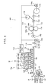
- FIG. 1 is a front view schematically showing the structure of an embodiment of an ink-jet recording device according to the invention
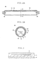
- FIG. 2A is a longitudinal sectional view schematically showing the structure of an exemplary fluorescent lamp used in UV irradiation units of the ink-jet recording device shown in FIG. 1
- FIG. 2B is a sectional view, taken along the line B-B, of the fluorescent lamp shown in FIG. 2A .
- active light-curable ink-jet recording devices which use an ultraviolet light-curable ink (UV-curable ink) as the active light-curable ink (also referred to as “active energy ray-curable ink”) that cures under irradiation with active light (also referred to as “active energy rays”) are described below.
- UV-curable ink ultraviolet light-curable ink
- active energy ray-curable ink active energy ray-curable ink
- an ink-jet recording device 10 has a transport section 12 which transports a recording medium P, an undercoat forming section 13 which coats an undercoating liquid onto the recording medium P, an undercoating liquid semi-curing section 14 which semi-cures the undercoating liquid that has been coated onto the recording medium P, an image recording section 16 which records an image on the recording medium P, an image fixing section 18 which fixes the image recorded on the recording medium P, and a control unit 20 which controls the ejection of ink droplets from the image recording section 16.
- An input unit 22 is connected to the control unit 20 of the ink-jet recording device 10.
- the input unit 22 may be an image reading unit such as a scanner or any of various types of devices which transmit image data, including image processing devices such as a personal computer. Any of various connection methods, whether wired or wireless, may be used to connect the input unit 22 and the control unit 20.
- the transport section 12 which has a feed roll 30, a transport roll 32, a transport roller pair 34 and a recovery roll 36, feeds, transports and recovers the recording medium P.
- the feed roll 30 has a web-type recording medium P wrapped thereon in the form of a roll, and feeds the recording medium P.
- the transport roll 32 is disposed on the downstream side of the feed roll 30 in the direction of travel of the recording medium P, and transports the recording medium P that has been let out from the feed roll 30 to the downstream side in the direction of travel.
- the transport roller pair 34 is a pair of rollers which are disposed on the downstream side of the transport roll 32 in the travel path of the recording medium P and which grip therebetween the recording medium P that has passed around the transport roll 32 and transport it to the downstream side in the direction of travel.
- the recovery roll 36 is disposed the furthest downstream on the travel path of the recording medium P.
- the recovery roll 36 takes up the recording medium P which has been fed from the feed roll 30, has been transported by the transport roll 32 and the transport roller pair 34, and has passed through positions facing the subsequently described undercoat forming section 13, undercoating liquid semi-curing section 14, image recording section 16 and image fixing section 18.
- transport roll 32, the transport roller pair 34 and the recovery roll 36 are connected to drive units (not shown) and rotated by the drive units.
- the transport roll 32 is disposed above the feed roll 30 in a vertical direction, and at a position farther from the recovery roll 36 than from the feed roll 30 in a horizontal direction. Moreover, the transport roll 32, the transport roller pair 34 and the recovery roll 36 are disposed linearly in a direction parallel to the horizontal direction.
- the transport section 12 is configured as described above and transports the recording medium P let out from the feed roll 30 upward while inclined at a given angle with respect to the vertical direction toward the side away from the recovery roll 36, following which the transport section 12 changes the direction of travel of the recording medium P at the transport roll 32 so that, after the recording medium P has passed the transport roll 32, it is transported horizontally toward the recovery roll 36.
- the recording medium P After the recording medium P has been let out from the feed roll 30, it is moved in an upwardly inclined direction with the surface on which images are to be recorded facing downward. After passing around the transport roll 32, the recording medium P is moved in a horizontal direction with the surface on which images are to be recorded facing upward.
- the undercoat forming section 13 is situated between the feed roll 30 and the transport roll 32; that is, on the downstream side of the feed roll 30 and on the upstream side of the transport roll 32 in the direction of travel of the recording medium P.
- the undercoat forming section 13 has a coating roll 60 for coating an undercoating liquid onto the recording medium P, a drive unit 62 which drives the coating roll 60, a reservoir 64 which supplies the undercoating liquid to the coating roll 60, a scraper roll 66 which adjusts the amount of undercoating liquid picked up by the coating roll 60, a scraper roll drive unit 67 which drives the scraper roll 66 (hereinafter referred to simply as the "drive unit 67") and a positioning unit 68 which supports the recording medium P so that the recording medium P assumes a predetermined position relative to the coating roll 60.
- the coating roll 60 is disposed between the feed roll 30 and the transport roll 32 in the travel path of the recording medium P so as to be in contact with the surface of the recording medium P which is traveling between the feel roll 30 and the transport roll 32 and on which images are to be formed. That is, the coating roll 60 is in contact with the downwardly facing surface of the recording medium P being transported from the feed roll 30 to the transport roll 32.
- the coating roll 60 which is a roll that is longer than the width of the recording medium P, is a so-called gravure roller on the surface (peripheral face) of which recessed features are formed at fixed, i.e., uniform, intervals.
- the shapes of the recessed features formed on the coating roll 60 are not subject to any particular limitation. Any of various shapes may be used, including round, rectangular, polygonal or star-like shapes. Alternatively, the recessed features may be formed as grooves extending over the entire circumference of the coating roll. Since the amount of undercoating liquid held on the surface of the coating roll 60 can be made constant, the coating roll 60 preferably has such a shape that recessed features are formed on its surface at fixed intervals. However, this is not the sole case of the present invention but a roll having no recessed features formed thereon may also be used.
- the drive unit 62 is a drive mechanism including a motor, and gears which transmit rotation of the motor to the coating roll 60 and rotates the coating roll 60.
- the drive unit 62 is not limited to this embodiment. Any of various other drive mechanisms may instead be used to rotate the coating roll 60, including pulley driving, belt driving and direct driving.
- the drive unit 62 causes the coating roll 60 to rotate in the direction opposite to the direction of travel of the recording medium P at the portion of contact therebetween (i.e., in the clockwise direction in FIG. 1 ).
- the reservoir 64 has a dish-like shape open at the top, and holds in the interior thereof the undercoating liquid.
- the reservoir 64 is disposed underneath and adjacent to the coating roll 60, such that a portion of the coating roll 60 is immersed in the undercoating liquid held within the reservoir 64.
- the undercoating liquid is fed to the reservoir 64 from a feed tank (not shown).
- the scraper roll 66 is a roll having substantially the same axial length as the coating roll 60.
- the scraper roll 66 is rotatably disposed in a state in which it is in contact with the surface of the coating roll 60. More specifically, the scraper roll 66 is disposed downstream of the reservoir 64 and upstream of the recording medium P in the rotational direction of the coating roll 60.
- the scraper roll 66 scrapes off that portion of the undercoating liquid picked up by the coating roll 60 when immersed in the reservoir 64 which is not needed, thereby setting the quantity of undercoating liquid adhering to the coating roll 60 to a fixed amount.
- the scraper roll 66 scrapes off undercoating liquid adhering to other portions of the coating roll 60 so that the portion of the coating roll 60 which comes in contact with the recording medium P has the undercoating liquid substantially only held in the recessed features.
- the scraper roll 66 scrapes off undercoating liquid excessively adhering to the surface of the coating roll 60 (i.e., surplus undercoating liquid) to make the amount of undercoating liquid adhering to the surface of the coating roll 60 constant, thus enabling the coating layer to be more uniformly formed on the recording medium.
- the drive unit 67 rotates the scraper roll 66 in the opposite direction from the rotational direction of the coating roll 60 so that the direction of movement of the scraper roll 66 surface and the direction of movement of the coating roll 60 at the position of contact between the scraper roll 66 and the coating roll 60 are the same (in the counterclockwise direction in FIG. 1 ).
- various drive mechanisms may be used to rotate the roll, including gear driving, pulley driving, belt driving and direct driving.
- the drive unit 67 rotates the scraper roll 66 in the opposite direction from the rotational direction of the coating roll 60 to prevent abrasion of the scraper roll 66 and the coating roll 60, thus enabling their replacement frequency to be reduced while enhancing the device durability.
- undercoating liquid excessively adhering to the coating roll 60 is preferably scraped off by a scraper roll as in the embodiment under consideration.
- this is not the sole case of the present invention but use may be made of a method using a blade in which the blade is brought into contact with the coating roll 60 to scrape off undercoating liquid excessively adhering to the coating roll 60.
- the positioning unit 68 has a first positioning roll 70 and a second positioning roll 72, and supports the recording medium P in such a way as to ensure that the recording medium P comes into contact with the coating roll 60 at a specified position.
- the first and second positioning rolls 70 and 72 are each situated on the opposite side of the recording medium P from the coating roll 60 and, in the direction of travel of the recording medium P, on either side of the coating roll 60; that is, one is situated on the upstream side, and the other is situated on the downstream side, of the coating roll 60. These first and second positioning rolls 70 and 72 support the recording medium P from the side of the recording medium P opposite to the side on which images are to be formed (i.e., the side to be coated with undercoating liquid).
- Any positioning mechanism may be used as long as it is configured such that members which individually support the coating roll 60 and the first and second positioning rolls 70 and 72 are placed in mutual contact.
- any positioning mechanism may be used as long as it is configured such that members which individually support the coating roll 60 and the first and second positioning rolls 70 and 72 are placed in mutual contact.
- use may be made of a mechanism in which the bearings of the respective members are placed in mutual contact, and a mechanism in which fixing members which fix in place the bearings are placed in mutual contact.
- the drive unit 62 causes the coating roll 60 to rotate in the direction opposite to the direction of travel of the recording medium P.
- the surface of the rotating coating roll 60 comes into contact with the scraper roll 66, thereby setting the amount of undercoating liquid retained on the surface to a fixed amount, then comes into contact with the recording medium P, thereby coating the undercoating liquid onto the recording medium P.
- undercoat a layer of undercoating liquid that has been smoothened and has a good, even, coating surface state can be formed on the recording medium P.
- the coating roll 60 that came into contact with the recording medium P is further rotated to be immersed again in the coating liquid within the reservoir 64.
- the undercoating liquid semi-curing section 14 includes a UV irradiation unit and is disposed so as to face the recording medium P.
- the UV irradiation unit has a fluorescent lamp emitting UV light, a housing which is disposed so as to surround the fluorescent lamp, has an opening formed on the recording medium P side and reflects light emitted from the fluorescent lamp, and a cooling mechanism which is disposed in the housing and blows air to the fluorescent lamp for its cooling, and irradiates UV light onto the recording medium P.
- the UV irradiation unit will be described later in detail in connection with the image fixing section 18.
- the undercoating liquid semi-curing section 14 exposes to UV light the entire width of the recording medium P which has been coated on the surface with the undercoating liquid and passes through a position opposed thereto, thereby rendering the undercoating liquid coated onto the surface of the recording medium P into a semi-cured state. Semi-curing of the undercoating liquid will be described later in further detail.
- the image recording section 16 in which ink droplets are ejected onto the recording medium to record an image and the image fixing section 18 in which the image formed on the recording medium in the image recording section 16 is cured to fix it on the recording medium are described.
- the image recording section 16 has a recording head unit 46 and ink tanks 50X, 50Y, 50C, 50M and 50K.
- the recording head unit 46 has recording heads 48X, 48Y, 48C, 48M and 48K.
- the recording heads 48X, 48Y, 48C, 48M and 48K are arranged in this order from the upstream side to the downstream side in the direction of travel of the recording medium P. Moreover, in the recording heads 48X, 48Y, 48C, 48M and 48K, the tips of the respective ink ejection portions are disposed so as to face the path of travel of the recording medium P; that is, so as to face the recording medium P which is transported over the travel path by the transport section 12 (also referred to below as simply "facing the recording medium P").
- the recording heads 48X, 48Y, 48C, 48M and 48K are full-line, piezoelectric ink-jet heads in which a large number of orifices (nozzles, ink ejection portions) are arranged at fixed intervals throughout in a direction perpendicular to the direction of travel of the recording medium P, that is, over the entire width of the recording medium P.
- These recording heads are connected to the subsequently described control unit 20 and the ink tanks 50X, 50Y, 50C, 50M and 50K.
- the amount of ink droplets ejected by the recording heads 48X, 48Y, 48C, 48M and 48K and the ejection timing of the droplets are controlled by the control unit 20.
- the recording heads 48X, 48Y, 48C, 48M and 48K eject inks of special color (X), yellow (Y), cyan (C), magenta (M) and black (K).
- a color image can be formed on the recording medium P by ejecting inks of various colors--special color (X), yellow (Y), cyan (C), magenta (M) and black (K)--from the respective recording heads 48X, 48Y, 48C, 48M and 48K toward the recording medium P while at the same time having the transport section 12 transport the recording medium P.
- the recording heads are piezoelectric (piezo) elements.
- piezo piezoelectric
- the invention is not limited in this regard. Any of various types of systems may be used in place of a piezo system, such as a thermal jet system which uses a heating element such as a heater to heat the ink and generate bubbles. In this latter system, the pressure of the bubbles propels the droplets of ink.
- any of various inks such as white, orange, violet or green ink may be used as the special colored ink ejected from the recording head 48X.
- the number of inks ejected from the recording head 48X is not limited to one but a plurality of inks may be ejected therefrom.
- this embodiment is not the sole case but the recording heads may be arranged in various orders.
- the inks ejected from the recording heads in the present embodiment are UV-curable inks.
- the ink tanks 50X, 50Y, 50C, 50M and 50K are provided for the recording heads 48X, 48Y, 48C, 48M and 48K.
- the respective ink tanks 50X, 50Y, 50C, 50M and 50K store inks of various colors for the recording heads, and supplies the stored inks to the corresponding recording heads 48X, 48Y, 48C, 48M and 48K.
- a tabular platen 56 is disposed at a position facing the recording heads 48X, 48Y, 48C, 48M and 48K on the side of the recording medium P where images will not be formed.
- the platen 56 supports the recording medium P which is transported through positions facing the respective recording heads from the side of the recording medium P on which images will not be formed; that is, from the opposite side of the recording medium P to that on which the recording head unit 46 is disposed. In this way, the distance between the recording medium P and the respective recording heads can be made constant, enabling high-resolution images to be formed on the recording medium P.
- the shape of the platen 56 is not limited to a flat plate, and may have a raised, curved surface shape on the recording head side.
- the recording heads 48X, 48Y, 48C, 48M and 48K are disposed at fixed distances from the platen.
- the image fixing section 18, which has UV irradiation units 52X, 52Y, 52C and 52M, and a final UV irradiation unit for curing 54, irradiates UV light onto the image formed on the recording medium P by the recording head unit 46, thereby semi-curing the image (that is, the inks) with the UV irradiation units 52X, 52Y, 52C and 52M, then curing it with the final UV irradiation unit for curing 54, thus fixing the image.
- the UV irradiation units 52X, 52Y, 52C and 52M are disposed on the downstream sides of the respective recording heads 48X, 48Y, 48C and 48M along the travel path of the recording medium P.
- the final UV irradiation unit for curing 54 is disposed on the downstream side of the recording head 48K along the travel path of the recording medium P. That is, the final UV irradiation unit for curing 54 is positioned on the downstream side of the recording head situated the furthest downstream of all the recording heads along the travel path of the recording medium P.
- the respective recording heads 48X, 48Y, 48C, 48M and 48K, the respective UV irradiation units 52X, 52Y, 52C and 52M, and the final UV irradiation unit for curing 54 are disposed in the following order, from the upstream to the downstream side of the travel path: recording head 48X, UV irradiation unit 52X, recording head 48Y, UV irradiation unit 52Y, recording head 48C, UV irradiation unit 52C, recording head 48M, UV irradiation unit 52M, recording head 48K, final UV irradiation unit for curing 54.
- the UV irradiation units 52X, 52Y, 52C and 52M and the final UV irradiation unit for curing 54 differ only in the size of the units, the target to be irradiated with UV light and the degree of cure.
- the UV irradiation units 52X, 52Y, 52C and 52M semi-cure the images formed by the respective recording heads
- the final UV irradiation unit for curing 54 differs only in that it irradiates higher intensity light than the other UV irradiation units so as to reliably cure both the undercoating liquid coated onto the recording medium P and images of all the respective inks.
- the final UV irradiation unit for curing 54 has the same basic construction as the UV irradiation units 52X, 52Y, 52C and 52M, the description given below for the UV irradiation unit 52X applies collectively to all of the above UV irradiation units, including the final UV irradiation unit for curing 54.
- UV irradiation unit 52X is described with reference to FIGS. 1 , 2A and 2B .
- the UV irradiation unit 52X has a fluorescent lamp 80 emitting UV light, a housing 82 which is disposed so as to surround the fluorescent lamp 80 and which has an opening formed on the recording medium P side, and a cooling mechanism 84 which is disposed within the housing 82 and which blows air to the fluorescent lamp 80 for its cooling.
- the UV irradiation unit 52X is disposed so as to face the travel path of the recording medium P.
- the fluorescent lamp 80 is a linear light source which emits UV light and is disposed so that a direction orthogonal to the direction of travel of the recording medium P is parallel to the axial direction in which the fluorescent lamp 80 extends.
- the fluorescent lamp 80 has a length which is larger than that of the recording medium P in the width direction, and is disposed over the entire width of the recording medium P.
- the fluorescent lamp 80 has a bulb 86, electrodes 88, a reflective film 90, and a phosphor film 92.
- the bulb 86 is a tubular (or cylindrical) member made of a material such as soda glass or fused silica (sterile glass). Tubes having a length in the range of from 500 mm to 800 mm may be used for the bulb 86. Tubes having diameters of 15.5 mm, 20 mm, 25.5 mm, 28 mm, 32 mm, and 38 mm may be used for the bulb 86.
- the electrodes 88 protrude into the space formed in the bulb 86, have each a filament through which electric current flows, and are disposed at both ends of the bulb 86.
- the bulb 86 and the electrodes 88 at both ends of the bulb 86 are disposed so as to hermetically seal the bulb 86, and mercury or other material is sealed within the bulb 86.
- the reflective film 90 is made of a light reflective material and is formed on the inner wall surface of the bulb 86.
- the phosphor film 92 is made of a phosphor which emits UV light at 280 to 400 nm, and is formed on the reflective film 90 and part of the inner wall surface of the bulb 86.
- the fluorescent lamp 80 is of a structure in which the bulb 86, the reflective film 90 and the phosphor film 92 are stacked on top of each other from the outside toward the center of the fluorescent lamp 80.
- neither the reflective film 90 nor the phosphor film 92 is formed on the bulb 86 on the recording medium P side (on the bottom side in FIG. 2B ) and these portions corresponding to the reflective film 90 and the phosphor film 92 are hereinafter referred to as apertures 94 and 96, respectively.
- the reflective film 90 and the phosphor film 92 have shapes satisfying the conditions ⁇ ⁇ , 60° ⁇ ⁇ ⁇ 150° and 30° ⁇ ⁇ ⁇ 90° wherein ⁇ represents the aperture angle of the aperture 94 for the reflective film 90 and ⁇ represents the aperture angle of the aperture 96 for the phosphor film 92.
- the aperture angle as used herein refers to an angle formed between a first line segment that connects the center of the section of the fluorescent lamp which is orthogonal to the longitudinal direction (i.e. the center of the reflective film 90 or the phosphor film 92 formed on the circumference of the bulb 86) and a first aperture end, and a second line segment that connects the center of the section and a second aperture end.
- the fluorescent lamp 80 has, on the recording medium P side of the bulb 86, a first region where both of the reflective film 90 and the phosphor film 92 are not formed on the bulb 86 and a second region where the phosphor film 92 is only formed thereon.
- the bulb 86 has the second region where the phosphor film 92 is directly formed on the bulb 86.
- the fluorescent lamp 80 has the arrangement as described above.
- the filaments of the electrodes 88 are preheated by application of electric current, electrons are released from emitters having an elevated temperature (emitters being coated on the filaments) to collide with mercury atoms sealed within the fluorescent lamp 80.
- Mercury generates UV light.
- the phosphor film 92 emits light at the respective wavelengths. The emitted light then travels through the aperture 94 toward the recording medium P directly or after having been reflected on the reflective film 90.
- the housing 82 is in the shape of a rectangular parallelepiped box and is disposed so as to surround the periphery of the fluorescent lamp 80.
- the housing 82 has an open surface on the side of the recording medium P. In other words, the surface of the housing 82 on the recording medium P side is opened and light emitted from the fluorescent lamp 80 passes through the opened surface to strike on the recording medium P.
- the cooling mechanism 84 is an air blowing machine such as a cooling fan or an air blower, and is disposed within the housing 82 on the side of the fluorescent lamp 80 away from the recording medium P (i.e., on the upper side of the fluorescent lamp 80 in FIG. 1 ). The cooling mechanism 84 blows air toward the fluorescent lamp 80 for its cooling.
- the cooling mechanism 84 also has a temperature sensor for detecting the temperature of the fluorescent lamp 80.
- the volume of air and the time of air blowing are adjusted to regulate the amount of cooling thereby maintaining the fluorescent lamp 80 at a constant temperature.
- An opening is preferably formed in the housing 82 so that air to be blown from the cooling mechanism 84 to the fluorescent lamp 80 is aspirated through the opening.
- the UV irradiation unit 52X is basically configured as described above.
- control unit 20 is connected to the respective recording heads 48X, 48Y, 48C, 48M and 48K of the recording head unit 46 and, using image data sent from the input unit 22 as the image recording signals, controls ink ejection/non-ejection from the respective recording heads 48X, 48Y, 48C, 48M and 48K so as to form images on the recording medium P.
- the ink-jet recording device 10 has the basic layout as described above.
- the term "semi-curing the undercoating liquid” as used herein signifies partial curing, and refers to the undercoating liquid in a partially cured, i.e., an incompletely cured, state.
- the degree of curing may be non-uniform; preferably, the degree of curing proceeds in the depth direction of the undercoating liquid.
- the undercoating liquid which is semi-cured is an undercoating liquid which forms an undercoat.
- radical polymerization tends to be inhibited at the surface of the undercoating liquid.
- semi-curing is non-uniform, there being a tendency for curing to proceed at the interior of the undercoating liquid and to be delayed at the surface.
- the undercoating liquid partially photocures, enabling the degree of cure of the undercoating liquid to be higher at the interior than at the exterior.
- the degree of cure in the undercoating liquid is likewise possible for the degree of cure in the undercoating liquid to be made higher at the interior than at the exterior by using this cationic-polymerizable undercoating liquid under humid conditions that have a cationic polymerization-inhibiting effect so as to induce partial photocuring.
- the semi-curing of the undercoating liquid i.e., the undercoat formed of undercoating liquid on the recording medium
- the undercoating liquid i.e., the undercoat formed of undercoating liquid on the recording medium
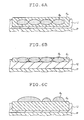
- high-density areas obtained by depositing about 12 pL of liquid ink (that is, droplets of ink) on the undercoating liquid in a semi-cured state having a thickness of about 5 ⁇ m that has been provided on a recording medium P are described below.
- FIG. 3 is a schematic sectional view of a recording medium where ink droplets have been deposited onto a semi-cured undercoating liquid.
- FIGS. 4A and 4B are schematic sectional views of recording media where ink droplets have been deposited onto an undercoating liquid that is in an uncured state
- FIG. 4C is a schematic sectional view of a recording medium where ink droplets have been deposited onto an undercoating liquid that is in a completely cured state.
- the degree of cure on the recording medium P side is higher than the degree of cure at the surface layer.
- three features are observable. That is, as shown in FIG. 3 , when ink d is deposited as droplets on a semi-cured undercoating liquid U, (1) a portion of the ink d emerges at the surface of the undercoating liquid U, (2) a portion of the ink d lies within the undercoating liquid U, and (3) the undercoating liquid is present between the bottom side of the ink d and the recording medium P.
- the undercoating liquid U When the ink d is deposited on the undercoating liquid U, if the undercoating liquid U and the ink d satisfy the above states (1), (2) and (3), the undercoating liquid U can be regarded as being in a semi-cured state.
- the droplets of ink d i.e., the ink droplets
- the ink droplets which have been deposited to a high density mutually connect, forming a film of the ink d (i.e., an ink film or ink layer), and thus providing a uniform and high color density.
- the quantity of regions where the undercoating liquid (i.e., the undercoat) is uncured per unit surface area is preferably smaller, and more preferably substantially smaller, than the maximum quantity of droplets of ink applied per unit surface area.
- the relationship between the weight M u (also referred to as M undercoating liquid ) of uncured regions of the undercoat per unit surface area and the maximum weight m i (also referred to as m ink ) of the ink ejected per unit surface area preferably satisfies the condition (m i /30) ⁇ M u ⁇ m i , more preferably satisfies the condition (m i /20) ⁇ M u ⁇ (m i /3), and most preferably satisfies the condition (m i /10) ⁇ M u ⁇ (m i /5).
- the "maximum weight of the ink ejected per unit surface area" refers to the maximum weight per color.
- the weight of uncured regions of the undercoating liquid per unit surface area is determined by a transfer test. Specifically, after completion of the semi-curing step (e.g., after exposure to active energy rays) and before deposition of the ink droplets, a permeable medium such as plain paper is pressed against the undercoating liquid which is in a semi-cured state, and the amount of the undercoating liquid that transfers to the permeable medium is determined by weight measurement. The measured value is defined as the weight of the uncured regions of the undercoating liquid.
- the maximum weight m i of the ink ejected per unit surface area becomes 0.04 g/cm 2 (assuming the density of the ink is about 1.1 g/cm 3 ).
- the weight M u per unit surface area of uncured regions of the undercoating liquid is preferably greater than 0.0013 g/cm 2 but less than 0.04 g/cm 2 , more preferably greater than 0.002 g/cm 2 but less than 0.013 g/cm 2 , and most preferably greater than 0.004 g/cm 2 but less than 0.008 g/cm 2 .
- the ink signifies partial curing, and refers to a state where the liquid ink (i.e., ink, colored liquid) is in a partially cured, but not a completely cured, state.
- the degree of cure may be non-uniform; preferably, the degree of cure proceeds in the depth direction of the ink liquid.
- the ink that is to be semi-cured is in the form of ink droplets which land on the undercoat or recording medium and form an ink layer.
- FIG. 5 is a schematic sectional view of a recording medium where a second ink d b has been deposited onto a semi-cured first ink d a .
- FIGS. 6A and 6B are schematic sectional views of recording media where droplets of the second ink d b have been deposited onto the first ink d a that is in an uncured state
- FIG. 6C is a schematic sectional view of a recording medium where droplets of the second ink d b have been deposited onto the first ink d a that is in a completely cured state.
- the "semi-cured state" of the first ink d a is similar to the above-described semi-cured state of the undercoating liquid. As shown in FIG. 5 , this is a state where, when the second ink d b is deposited as droplets onto the first ink d a , (1) a portion of the second ink d b emerges at the surface of the first ink d a , (2) a portion of the second ink d b lies within the first ink d a , and (3) the first ink d a is present below the second ink d b .
- a cured film (colored film A) of the first ink d a and a cured film (colored film B) of the second ink d b can be suitably superimposed, enabling good color reproduction to be achieved.
- the second ink d b is deposited as droplets on the first ink d a with the latter in an uncured state, either or both of the following occur: all of the second ink d b lies within the first ink d a as shown in FIG. 6A ; a state arises where, as shown in FIG. 6B , the first ink d a is not present below the second ink d b .
- the droplets are independent of each other, causing the color saturation of the secondary color to decrease.
- the quantity of regions where the first ink d a is uncured per unit surface area is preferably smaller, and more preferably substantially smaller, than the maximum quantity of droplets of the second ink d b applied thereon per unit surface area.
- the relationship between the weight M da (also referred to as M ink A ) of uncured regions of the first ink d a layer per unit surface area and the maximum weight m db (also referred to as m ink B ) of the second ink d b ejected thereon per unit surface area preferably satisfies the condition (m db /30) ⁇ M da ⁇ m db , more preferably satisfies the condition (m db /20) ⁇ M da ⁇ (m db/ 3), and most preferably satisfies the condition (m db /10) ⁇ M da ⁇ (m db /5).
- the weight of the uncured regions of the first ink d a per unit surface area is determined by a transfer test. Specifically, after completion of the semi-curing step (e.g., after exposure to active energy rays) and before deposition of the droplets of the second ink d b , a permeable medium such as plain paper is pressed against the layer of the first ink d a which is in a semi-cured state, and the quantity of the first ink d a that transfers to the permeable medium is determined by weight measurement. The measured value is defined as the weight of the uncured regions of the ink liquid.
- the maximum weight m db of the second ink d b ejected per unit surface area becomes 0.04 g/cm 2 (assuming the density of the second ink d b to be about 1.1 g/cm 3 ).
- the weight M da per unit surface area of uncured regions of the first ink d a layer is preferably greater than 0.0013 g/cm 2 but less than 0.04 g/cm 2 , more preferably greater than 0.002 g/cm 2 but less than 0.013 g/cm 2 , and most preferably greater than 0.004 g/cm 2 but less than 0.008 g/cm 2 .
- the unpolymerization ratio (i.e., A after polymerization /A before polymerization) is preferably at least 0.2 but not more than 0.9, more preferably at least 0.3 but not more than 0.9, and most preferably at least 0.5 but not more than 0.9.
- a before polymerizacion is the infrared absorption peak absorbance attributable to polymerizable groups before the polymerization reaction
- a after polymerization is the infrared absorption peak absorbance attributable to polymerizable groups after the polymerization reaction.
- the polymerizable compound included in the undercoating liquid and/or the ink is an acrylate monomer or a methacrylate monomer
- absorption peaks based on polymerizable groups acrylate groups, methacrylate groups
- the above unpolymerization ratio is preferably defined in terms of the absorbances of these peaks.
- the polymerizable compound is an oxetane compound
- an absorption peak based on polymerizable groups (oxetane rings) can be observed near 986 cm -1 .
- the above unpolymerization ratio is thus preferably defined in terms of the absorbance of this peak.
- the polymerizable compound is an epoxy compound
- an absorption peak based on the polymerizable groups (epoxy groups) can be observed near 750 cm -1 .
- the above unpolymerization ratio is preferably defined in terms of the absorbance of this peak.
- a commercial infrared spectrophotometer may be used as the means for measuring the infrared absorption spectrum.
- the spectrophotometer may be either a transmission-type or reflection-type system. Suitable selection according to the form of the sample is preferred. Measurement may be carried out using, for example, an FTS-6000 infrared spectrophotometer manufactured by Bio-Rad.
- the unpolymerization ratio may be quantitatively measured from the percent conversion of ethylenically unsaturated groups or cyclic ether groups.
- the method used to semi-cure the undercoating liquid and/or the ink is exemplified by known thickening methods, e.g., (1) methods that use an agglomerating effect, such as by furnishing a basic compound to an acidic polymer or by furnishing an acidic compound and a metal compound to a basic polymer; (2) methods wherein the undercoating liquid and/or the ink is prepared beforehand at a high viscosity, then the viscosity is lowered by adding thereto a low-boiling organic solvent, after which the low-boiling organic solvent is evaporated so as to return the liquid to its original high viscosity; (3) methods in which the undercoating liquid and/or the ink prepared at a high viscosity is first heated, then is cooled so as to return the liquid to its original high viscosity; and (4) methods in which the undercoating liquid and/or the ink is semi-cured through a curing reaction induced by exposing the undercoating liquid and/or the in
- Methods in which the undercoating liquid and/or the ink is semi-cured through a curing reaction induced by exposing the undercoating liquid and/or the ink to active energy rays or heat refers herein to methods in which the polymerization reaction on polymerizable compounds at the surface of the undercoating liquid and/or the ink furnished to the recording medium is carried out incompletely.
- the polymerization reaction tends to be inhibited by the influence of oxygen present in air. Therefore, by controlling the conditions of exposure to active energy rays or heat, it is possible to trigger the reaction for semi-curing the undercoating liquid and/or the ink.
- the amount of energy required to semi-cure the undercoating liquid and/or the ink varies with the type and content of polymerization initiator.
- an amount of about 1 to about 500 mJ/cm 2 is generally preferred.
- the energy is applied as heat, from 0.1 to 1 second of heating under temperature conditions where the surface temperature of the recording medium falls within a temperature range of 40 to 80°C is preferred.
- active energy rays or heat such as with active rays or heating, promotes the generation of active species by decomposition of the polymerization initiator.
- the increase in active species or the rise in temperature promotes the curing reaction through polymerization or crosslinking of polymerizable or crosslinkable materials induced by the active species.
- a thickening may also be suitably carried out by exposure to active rays or by heating.
- the ink-jet recording device of the invention is described below in further detail by referring to the operation of the ink-jet recording device 10, that is, its recording action on the recording medium P.
- FIGS. 7A to 7D are views schematically showing steps of forming an image on a recording medium, respectively.
- the recording medium P having been let out from the feed roll 30 is transported in a specified direction (direction "Y" in FIG. 1 ) by rotation of the transport roll 32 and the transport roller pair 34.
- the recording medium P in this embodiment is a web with a certain length or more and is transported without being cut.
- the recording medium P having been let out from the feed roll 30 comes into contact with the coating roll 60 of the undercoat forming section 13 and the undercoating liquid is applied onto the surface thereof to form an undercoat U.
- the drive unit 62 causes the coating roll 60 to rotate in the direction opposite to the direction of travel of the recording medium P.
- the recording medium P on which the undercoat U has been formed by application of the undercoating liquid is further transported by the transport roll 32 and the transport roller pair 34 of the transport section 12 and passes through the position facing the undercoating liquid semi-curing section 14.
- the undercoating liquid semi-curing section 14 irradiates with ultraviolet light, the recording medium P onto which the undercoating liquid has been applied and which is passing through the position facing the section 14, thereby semi-curing the undercoat U on the recording medium P.
- the recording medium P having thereon the semi-cured undercoating liquid is further transported by the transport roll 32 and the transport roller pair 34 of the transport section 12 and passes through the position facing the recording head 48X.
- the recording head 48X ejects ink droplets from its ejection orifices to form an image on the recording medium P which is being transported by the transport section 12 and passing through the position opposed thereto.
- the recording head 48X ejects a first ink droplet d1 onto the recording medium P.
- the first ink droplet d1 ejected from the recording head 48X is deposited onto the surface of the undercoat U.
- the undercoat U is in a semi-cured state and has an uncured surface, and is therefore receptive to the ink droplet d1.
- the recording head 48X ejects a second ink droplet d2 in proximity to the position where the previously ejected first ink droplet d1 was deposited.
- the undercoat U is also in a semi-cured state and has an uncured surface, and is therefore receptive to the ink droplet d2.
- Ink droplets are thus ejected from the recording head 48X in accordance with the control by the control unit 20 and deposited onto the recording medium P to form an image.
- the recording medium P having the image formed by the recording head 48X is further transported by the transport section 12 and passes through the position facing the UV irradiation unit 52X disposed downstream from the recording head 48X.
- the UV irradiation unit 52X irradiates the recording medium P passing through the position opposed thereto with ultraviolet light to semi-cure the image formed by the recording head 48X on the recording medium P, that is, semi-cure the ink droplets having been deposited onto the recording medium P.
- the recording medium P is further transported and passes in order through the positions facing the recording head 48Y, the UV irradiation unit 52Y, the recording head 48C, the UV irradiation unit 52C, the recording head 48M, the UV irradiation unit 52M, and the recording head 48K, respectively.
- the recording medium P passed through the positions facing the recording head 48X and its corresponding UV irradiation unit 52X formation of an image and semi-curing of the formed image are performed each time the recording medium P passes through the positions facing the recording head of each color and its corresponding UV irradiation unit.
- the recording medium P passes through the position facing the final UV irradiation unit for curing 54.
- the final UV irradiation unit for curing 54 irradiates the recording medium P with more intense ultraviolet light than the other UV irradiation units to cure the whole of the images on the recording medium P formed by the various recording heads including the image recorded by the recording head 48K as well as the undercoating liquid.
- a color image is thus formed on the recording medium P.
- the recording medium P having the color image formed thereon is further transported by the transport roll 32 and the transport roller pair 34 to be taken up onto the recovery roll 36.
- the ink-jet recording device 10 thus forms the image on the recording medium P.
- the fluorescent lamps 80 of the UV irradiation units 52X, 52Y, 52C and 52M each have the reflective film 90 and the phosphor film 92 stacked on top of each other inside the bulb 86 with the apertures 94, 96 formed on the recording medium P side, and the apertures 94, 96 have such shapes that the aperture angles ⁇ and ⁇ satisfy the conditions ⁇ ⁇ , 60° ⁇ ⁇ ⁇ 150° and 30° ⁇ ⁇ ⁇ 90°.
- Higher intensity light can be emitted toward the side of the recording medium P, which ensures semi-curing or curing of the undercoating liquid and/or ink on the recording medium P in a short time, whereby the recording medium P can be transported at a higher speed to achieve higher productivity.
- the recording medium P can be irradiated with high intensity light in a substantially uniform manner by providing a reflective film and setting the aperture angles of the apertures for the reflective film and the phosphor film in the above-defined ranges.
- fluorescent lamp Light from the fluorescent lamp can be thus used efficiently. Therefore, an inexpensive fluorescent lamp can be employed to manufacture the ink-jet recording device at a low cost.
- fluorescent lamps use less power than metal halide lamps, high-pressure mercury vapor lamps and other active energy ray-irradiating devices, whereby power consumption of the ink-jet recording device can be reduced.
- high intensity light can be selectively emitted toward the recording medium P side with the use of a fluorescent lamp, which enables the light intensity and irradiation area to be adjusted without relying on precise reflection design using reflective members or other members.
- ink can be reliably semi-cured to a desired level to record a high-resolution image.
- the reflective film inside the bulb of the fluorescent lamp (more specifically on the inner wall surface of the bulb), high intensity light can be emitted toward the side of the recording medium P without disposing a reflector or other reflective member on the circumference of the fluorescent lamp, which avoids the necessity of leaving space for disposing a reflective member such as a reflector on the circumference of the fluorescent lamp, thus enabling the UV irradiation units and the image fixing section and hence the ink-jet recording device to be downsized.
- the fluorescent lamp 80 does not emit high intensity light to the areas other than the recording medium P.
- the housing 82 having the opening formed on the recording medium P side is disposed so as to surround the fluorescent lamp 80, which further ensures that light emitted from the fluorescent lamp 80 reaches the recording medium P while it is prevented from being irradiated onto the other areas than the recording medium P.
- the cooling mechanism 84 serves to maintain the fluorescent lamp 80 at a constant temperature, so that the amount of light emitted from the fluorescent lamp 80 is prevented from varying with the temperature and can be made constant. Ink and/or undercoating liquid can be thus consistently semi-cured or cured with a constant amount of light.
- the cooling mechanism 84 preferably adjusts the surface temperature of the fluorescent lamp 80 and more specifically the temperature of its surface away from the recording medium P in the range of from 30°C to 60°C and also the temperature variations within 5°C.
- the amount of light emitted from the fluorescent lamp 80 can be made constant while offering high power by maintaining the temperature within the above-defined range.
- the ink droplets having been deposited onto the recording medium can be prevented from permeating the recording medium to cause image bleed, thus enabling a high-resolution image to be formed. It also becomes possible to use a recording medium which has a low adhesion to ink droplets, namely, may repel ink droplets having been deposited thereonto. In other words, image recording on various recording media becomes possible.
- the coating roll 60 By using the coating roll 60 and, moreover, by rotating the coating roll 60 in a direction opposite to the direction of travel of the recording medium P to coat undercoating liquid onto the recording medium P, disruption of the surface of the undercoating liquid on the recording medium P when the coating roll 60 separates from the recording medium P after having applied undercoating liquid to the recording medium P can be prevented, enabling the undercoat U having an improved surface state to be formed on the recording medium P.
- the migration of ink droplets can be prevented in cases where ink droplets ejected from the recording heads are deposited in close proximity on the recording medium, such as when ink droplets of a single color having portions which mutually overlap are deposited on a recording medium or even when ink droplets of different colors having portions which mutually overlap are deposited on a recording medium.
- the UV irradiation unit corresponding to the recording head disposed on the furthest downstream side serves as the final UV irradiation unit for curing and, because it emits higher intensity UV light than the other UV irradiation units, has the ability to reliably cure images that have been formed on the recording medium.
- the final UV irradiation unit for curing 54 is configured in the same manner as the UV irradiation units 52X, 52Y, 52C and 52M in the embodiment under consideration.
- use may also be made of various UV light sources such as metal halide lamps and high-pressure mercury vapor lamps for the final UV irradiation unit for curing 54.
- the ink-jet recording device is preferably configured so that the UV irradiation units each including the fluorescent lamp 80 are used for semi-curing the undercoating liquid and/or ink, whereas a metal halide lamp, high-pressure mercury vapor lamp or other lamp is used for the final UV irradiation unit for curing 54.
- the fluorescent lamp 80 In view of prevention of clogging of the recording head nozzles, production of prints at a high rate, appropriate semi-curing as well as further device downsizing, energy saving and cost reduction, it is preferable for the fluorescent lamp 80 to be provided in every UV irradiation unit for semi-curing the undercoating liquid and/or ink. However, this is not the sole case of the present invention.
- the ink-jet recording device may also be configured so that at least one of the UV irradiation units includes the fluorescent lamp 80 and the other UV irradiation units each include a metal halide lamp, a high-pressure mercury vapor lamp, a fluorescent lamp having a reflective film and/or a phosphor film which does not satisfy the above-defined range, or a fluorescent lamp having no reflective film.
- the fluorescent lamp 80 is preferably disposed at such a position that the shortest distance h (mm) between the irradiation surface of the fluorescent lamp 80 and the recording medium P is in the range of from 0.5 mm to 1.5 mm.
- the recording medium P can be irradiated with light with high efficiency by disposing the fluorescent lamp 80 at the position where the above-defined range is satisfied.
- the amount of light irradiated onto other portions than the recording medium P after having been emitted from the fluorescent lamp 80 can be reduced by disposing the housing 82 at a position satisfying the above-defined range.
- the ink droplets on the recording medium can be prevented from getting out of shape, enabling a high-resolution image to be formed.
- the undercoating liquid has a viscosity of preferably at least 10 mPa ⁇ s but not more than 500 mPa ⁇ s, and more preferably at least 50 mPa ⁇ s but not more than 300 mPa ⁇ s.
- undercoating liquid viscosity of at least 10 mPa ⁇ s, and more preferably at least 50 mPa ⁇ s, as noted above, it is possible to coat the undercoating liquid onto even a recording medium to which liquid does not readily adhere.
- the ink-jet recording device 10 is described below in further detail with reference to specific examples.
- a linear tube with a diameter of 32 mm was used for the bulb and a phosphor emitting light at a central wavelength of 365 nm was used for the phosphor film in the fluorescent lamp 80.
- the fluorescent lamp 80 was disposed at such a position that the shortest distance h between the irradiation surface of the fluorescent lamp and the recording medium P was 1 mm, whereas the housing 82 was disposed at such a position that the shortest distance H between the housing 82 and the recording medium P was 1 mm.
- the ink-jet head used was one having a resolution of 600 dpi.
- the recording head was wiped off. Thereafter, whether or not the recording head nozzles were clogged was checked from the state of ejection from the recording head nozzles. More specifically, the recording head following wiping off was rated "excellent" when the state of non-ejection was not found in any nozzle, "good” when some of the nozzles were in the state of non-ejection but could be recovered with a simple maintenance operation, “fair” when some of the nozzles were in the state of non-ejection but could be recovered with a usual maintenance operation, and “poor” when some of the nozzles were in the state of non-ejection and could not be recovered thus requiring replacement with a new recording head.
- Table 1 Aperture angle ⁇ in reflective film Aperture angle ⁇ in phosphor film Productivity (high-speed performance) Nozzle clogging Evaluation 210° 180° 100 mm/s Poor Poor 120° 200 mm/s Poor Poor 90° 300 mm/s Poor Poor 60° 400 mm/s Poor Poor 30° 300 mm/s Poor Poor 180° 180° 100 mm/s Poor Poor 120° 200 mm/s Poor Poor 90° 300 mm/s Poor Poor 60° 400 mm/s Poor Poor 30° 300 mm/s Poor Poor 170° 180° 100 mm/s Poor Poor 120° 200 mm/s Poor Poor 90° 300 mm/s Poor Poor 60° 400 mm/s Poor Poor 30° 300 mm/s Poor Poor 150° 180° 100 mm/s Fair Poor 120° 200 mm/s Fair Poor 90° 400 mm/s Fair Fair 60° 600 mm/s Fair Fair 30° 400 mm/s Fair Fair 120° 180° 100 mm/s Good Poor 120° 200 mm/s Good
- Table 1 shows that nozzle clogging can be suppressed by adjusting the aperture angle ⁇ of the aperture for the reflective film to not more than 150°; can be further suppressed at an aperture angle ⁇ of not more than 120°, enabling the nozzles to be recovered with a simple maintenance operation; and can be prevented at an aperture angle ⁇ of not more than 60°.
- ink droplets can be semi-cured even at a recording medium P transport speed of 400 mm/s while also suppressing nozzle clogging, whereby high-resolution images can be consistently and rapidly produced for a long period of time.
- the reflective film of the fluorescent lamp 80 preferably has a transmittance of not more than 10%.
- a reflective film transmittance of not more than 10% light is more reliably prevented from being emitted from the other areas than the apertures, whereby the recording medium P can be irradiated with higher intensity light to achieve further improved productivity. UV light is also more reliably prevented from reaching the recording heads.
- the various effects as described above can be achieved by providing the fluorescent lamp with such a shape that the aperture angle ⁇ of the aperture for the reflective film and the aperture angle ⁇ of the aperture for the phosphor film satisfy ⁇ ⁇ ⁇ , 60° ⁇ ⁇ ⁇ 150° and 30° ⁇ ⁇ ⁇ 90°.
- the aperture angles in the phosphor film and the reflective film irrespective of the aperture shapes in the phosphor film and the reflective film, curing in a shorter period of time is possible by setting the transmittance of the reflective film in the fluorescent lamp to not more than 10%. The transport speed of the recording medium and hence the productivity can be improved.
- An ink-jet recording device of the same structure as in the first example was used in this example, and the print productivity was measured using four fluorescent lamps in which the reflective films had transmittance values of 30%, 20%, 10% and 5%, respectively.
- the aperture in the reflective film had an aperture angle of 90°
- the aperture in the phosphor film had an aperture angle of 60°.
- Table 2 Transmittance of reflective film Productivity (high-speed performance) 30% 50 mm/s 20% 100 mm/s 10% 400 mm/s 5% 600 mm/s
- the productivity can be drastically improved by setting the reflective film transmittance to not more than 10%. It is clear that a similar tendency is seen even if the aperture angle is changed.
- the aperture for the reflective film and that for the phosphor film in the fluorescent lamp preferably have shapes which are symmetric with respect to the axial plane connecting the center of the fluorescent lamp (i.e., axis of the tubular member) with the recording medium.
- the apertures for the reflective film and the phosphor film so as to have symmetric shapes with respect to the axial plane connecting the center of the fluorescent lamp with the recording medium, light emitted from the fluorescent lamp can be irradiated onto the recording medium which is at the shortest distance from the fluorescent lamp, while also reducing the area where light emitted from the fluorescent lamp is irradiated.
- the recording medium can be irradiated with higher intensity light.
- light is more reliably prevented from reaching the adjacent recording heads to cause their nozzles to be clogged.
- a getter is preferably sealed within the fluorescent lamp.
- the getter included therein can prolong the service life of the fluorescent lamp. In other words, the intensity of light emitted from the fluorescent lamp can be maintained for a long time to enable the replacement frequency and the running costs to be reduced.
- the cooling mechanism is provided in the housing, but the present invention is not limited to this as long as the fluorescent lamp can be cooled.
- a cooling mechanism may be separately disposed.
- UV irradiation units by disposing UV irradiation units between recording heads of the respective ink colors and curing the image areas on the recording medium each time an image is recorded at each of the respective recording heads, as noted above, it is possible to prevent ink of different colors from intermingling, thus enabling higher resolution images to be formed. Accordingly, a UV irradiation unit was positioned at each of the recording heads.
- the present invention is not limited in this regard. To illustrate, in an alternative arrangement, a single UV irradiation unit may be disposed for a plurality of recording heads.
- the recording head unit has recording heads of a total of five colors consisting of a special color (X) and yellow (Y), cyan (C), magenta (M) and black (K).
- X special color
- Y yellow
- C cyan
- M magenta
- K black
- the recording heads of the respective colors may be disposed in any order without any particular limitation.
- the ink-jet recording device of the invention may be one which uses a single recording head to form an image on the recording medium, then irradiates the image with UV light to form a single-color image.
- FIG. 8 is a front view showing, in simplified form, a digital label printer which uses an ink-jet recording device according to the invention
- FIG. 9 is a longitudinal sectional view of a recording medium P for printing labels such as may be used in the digital label printer shown in FIG. 8 .
- a digital label printer in the present embodiment records an image onto a web-type recording medium for printing labels at an image forming section, then makes label-shaped slits in the medium P with a die cutter in a post-treatment section.
- the printer carries out, as a subsequent step, a waste removal operation in which unnecessary portions of the pressure-sensitive adhesive sheet are peeled from the backing sheet (peel sheet) and removed.
- an active ray curing-type digital label printer which uses a UV-curable ink as the active ray-curable ink that cures upon exposure to active rays is described by way of illustration.
- the invention is not limited in this regard, and may be applied to digital label printers which use any of various kinds of active ray-curable inks, as well as to any other type of digital label printer.
- a web-type recording medium P for printing labels (also referred to below as simply “recording medium P") used in the present embodiment has a two-layer construction composed of a peel sheet 182 as a backing sheet on which is laminated a pressure-sensitive adhesive sheet 180 coated on the back side thereof with a pressure-sensitive adhesive 180a.
- a digital label printer 100 has a transport section 110; an undercoat forming section 13; an undercoating liquid semi-curing section 14; an image forming section 112 including an image recording section 16 and an image fixing section 18; a post-treatment section 114; and a control unit 116.
- the transport section 110 transports the web-type recording medium P for printing labels in a fixed direction (from left to right in FIG. 8 ).
- the image forming section 112 and the post-treatment section 114 are arranged in this order in the direction of travel of the recording medium P; that is, in the upstream to downstream direction, more specifically in the order of the undercoat forming section 13, the undercoating liquid semi-curing section 14, the image forming section 112 and the post-treatment section 114.
- the control unit 116 is connected to the undercoat forming section 13, the undercoating liquid semi-curing section 14, the transport section 110, the image forming section 112 and the post-treatment section 114, and controls their respective operations.
- the transport section 110 has a feed roll 30, a transport roll 32, transport roller pairs 126, 128, 130 and 132, a product roll 134, and transport motors 128a and 134a.
- the feed roll 30 has the web-type recording medium P for printing labels wound thereon in the form of a roll.
- the transport roll 32 and the transport roller pairs 126, 128, 130 and 132 are arranged in this order from the upstream to the downstream side of the travel path of the recording medium P.
- the transport roll 32 and the transport roller pairs 126, 128, 130 and 132 let out the recording medium P from the feed roll 30, and transport the recording medium P in a given direction (in the present embodiment, from left to right in FIG. 8 ).
- the transport roll 32 changes the travel path of the recording medium P from the obliquely upward direction to the horizontal direction.
- the product roll 134 which is disposed the furthest downstream on the recording medium P travel path, i.e., in the direction of transport, takes up the recording medium P that has been transported over the travel path by the transport roll 32 and the transport roller pairs 126, 128, 130 and 132 and has passed through the undercoat forming section 13, the undercoating liquid semi-curing section 14, the image forming section 112, and the post-treatment section 114.
- the transport motors 128a and 134a are connected to, respectively, the transport roller pair 128 and the product roll 134, and rotatably drive the transport roller pair 128 and the product roll 134.
- the transport roller pair 128 and the product roll 134 connected to the transport motors 128a and 134a, respectively, are driven to rotate and thus serve as the drive rollers for transporting the recording medium P.
- the other transport roller pairs 126, 130 and 132 and the transport roll 32 are driven rollers which rotate with movement of the recording medium P and regulate the recording medium P on the travel path.
- the transport motors 128a and 134a rotatably drive the transport roller pair 128 and the product roll 134.
- the recording medium P is let out from the feed roll 30, passes through the undercoat forming section 13, the undercoating liquid semi-curing section 14, the image forming section 112, and the post-treatment section 114, and is taken up onto the product roll 134.
- a transport buffer is provided between the image forming section 112 and the post-treatment section 114.
- the transport motors 128a and 134a are connected to a subsequently described transport motor controller and their rotational speeds thereby controlled. This in turn controls the speed at which the web-type recording medium P for printing labels is transported by the transport section 110.
- transport roller pairs which function as drive roller pairs.
- transport motors may be provided for all the transport roller pairs so that all the transport roller pairs function as drive roller pairs.
- the undercoat forming section 13 includes a coating roll 60, a drive unit 62, a reservoir 64, a scraper roll 66, a drive unit 67 and a positioning unit 68.
- the arrangement and function of each element of the undercoat forming section 13 are the same as those in the undercoat forming section 13 of the ink-jet recording device 10 as described above, and therefore their detailed description is omitted.
- the coating roll 60 of the undercoat forming section 13 contacts the recording medium P as it is rotated in the direction opposite to the direction of travel of the recording medium P, whereby the undercoating liquid is applied onto the surface of the recording medium P.
- the undercoat is thus formed on the surface of the recording medium P.
- the undercoating liquid semi-curing section 14 is disposed on the downstream side of the undercoat forming section 13 in the direction of travel of the recording medium P.
- the layout and function of the undercoating liquid semi-curing section 14 in this embodiment are the same as those of the undercoating liquid semi-curing section 14 of the ink-jet recording device 10 described above and therefore their detailed description is omitted here.
- the undercoating liquid semi-curing section 14 semi-cures the undercoat by irradiating with ultraviolet light the recording medium P which has the undercoat formed thereon through application of the undercoating liquid and which is transported by the transport section 110 to pass through the position opposed thereto.
- the image forming section 112 includes the image recording section 16 and the image fixing section 18.
- the image recording section 16 and the image fixing section 18 are configured in the same manner as the image recording section 16 and the image fixing section 18 of the ink-jet recording device 10 shown in FIG. 1 and therefore their detailed description is omitted.
- the image recording section 16 includes a recording head unit 46 having recording heads 48X, 48Y, 48C, 48M and 48K, and the image fixing section 18 includes four UV irradiation units 52X, 52Y, 52C and 52M and a final UV irradiation unit for curing 54.
- the recording heads 48X, 48Y, 48C, 48M and 48K as well as the UV irradiation units 52X, 52Y, 52C, 52M and 54 are arranged, from the upstream to the downstream side in the direction of travel of the recording medium P, in the following order: recording head 48X, UV irradiation unit 52X, recording head 48Y, UV irradiation unit 52Y, recording head 48C, UV irradiation unit 52C, recording head 48M, UV irradiation unit 52M, recording head 48K and final UV irradiation unit for curing 54.
- the image forming section 112 ejects ink droplets from each of the recording heads, then cures the ink droplets on the recording medium P by applying UV light from each of the UV irradiation units 52X, 52Y, 52C, 52M and 54, thereby forming an image.
- the post-treatment section 114 is disposed on, in the recording medium P travel direction, the downstream side of the UV irradiation unit 54 corresponding to the recording head 48K. It has a varnish coater 162 and an UV irradiator 164 for coating the image surface with a clear, active ray-curable liquid (in the present embodiment, a clear, UV-curable liquid) and improving the gloss, a die cutter 166 for making label-shaped slits in the web-type recording medium P, and a waste roll 172 for peeling off unnecessary portions of the recording medium P.
- a varnish coater 162 and an UV irradiator 164 for coating the image surface with a clear, active ray-curable liquid (in the present embodiment, a clear, UV-curable liquid) and improving the gloss
- a die cutter 166 for making label-shaped slits in the web-type recording medium P
- a waste roll 172 for peeling off unnecessary portions of the recording medium P.
- the transport buffer is provided between the UV irradiation unit 54 corresponding to the recording head 48K and the varnish coater 162.
- the varnish coater 162 is a clear liquid feeding means which feeds active ray- (in this embodiment, ultraviolet light-) curable clear liquid (referred to below as “active ray-curable clear liquid” or simply “clear liquid”) to the surface of the recording medium P, and which is situated on the downstream side, in the travel direction of the recording medium P, of the UV irradiation unit 54 corresponding to the recording head 48K.
- active ray-curable clear liquid active ray-curable clear liquid
- the varnish coater 162 has a pair of coating rolls to the surface of which adheres (on which has been impregnated) a UV-curable clear liquid, and which rotate in accordance (synchronous) with movement of the recording medium P while nipping the recording medium P, thereby coating the surface of the foil-stamped recording medium P (the side on which an image has been formed) with the UV-curable clear liquid.
- the clear liquid coated by the varnish coater 162 is an active ray-curable clear liquid which can be cured by exposure to ultraviolet light.
- exemplary clear liquids include cationic-polymerizable compositions, radical-polymerizable compositions and aqueous compositions which contain as the primary ingredients at least a polymerizable compound and a photoinitiator. The clear liquid is described in detail later in the specification.
- the UV irradiator 164 is disposed on the downstream side of the varnish coater 162 in the travel direction of the recording medium P.
- the UV irradiator 164 irradiates the surface of the recording medium P with active rays (in this embodiment, ultraviolet light), thereby curing the UV-curable clear liquid that has been coated onto the surface of the recording medium P.
- the UV irradiator 164 may also adopt various layouts such as the one shown in the UV irradiation units 52X, 52Y, 52C, 52M and 54 described above.
- the UV-curable clear liquid is coated onto the surface of the recording medium P and cured, enabling luster to be imparted to the image side of the recording medium P and making it possible to improve the image quality.
- the die cutter 166 makes slits 180b of a desired label shape in only the pressure-sensitive adhesive sheet 180 of a printed, web-type recording medium P for printing labels, as shown in FIG. 9 .
- the die cutter 166 is situated on the downstream side of the UV irradiator 164 in the travel direction of the recording medium P, and has a cylinder cutter 168 disposed on the image-forming side of the recording medium P and an anvil roller 170 disposed on the opposite side of the recording medium P from the cylinder cutter 168.
- the cylinder cutter 168 is composed of a cylinder 168a and a plurality of slitting blades 168b which are wound around the cylindrical surface of the cylinder 168a and are formed according to the shape and arrangement of the labels.
- the die cutter 166 preferably undergoes an intermittently rocking motion, that is, adjusts the rotational speed and rotational direction to form slits in the pressure-sensitive adhesive sheet 180.
- the die cutter 166 while nipping the recording medium P between the cylinder cutter 168 and the anvil roller 170, undergoes an intermittently rocking rotation which is synchronous with the transport speed of the recording medium P, causing the slitting blades 168b to make label-shaped slits in only the pressure-sensitive adhesive sheet 180 of the recording medium P, thus producing labels in the recording medium with high efficiency.
- the waste roll 172 peels from the peel sheet 182 and takes up unnecessary portions (label borders) of the pressure-sensitive adhesive sheet 180 which do not form labels (finished product) L.
- the thus taken up recording medium P after unnecessary portions have been peeled that is, the recording medium P in a state where only the labels L remain adhering to the peel sheet 182, is then taken up onto the product roll 134, giving the final product.
- the control unit 116 has a memory which stores recording image data for ink ejection from the recording heads 48X, 48Y, 48C, 48M and 48K of the recording head unit 46, a head drive controller for controlling the drive of the recording heads 48X, 48Y, 48C, 48M and 48K of the recording head unit 46 based on the recording image data, an image data analyzer for analyzing the shapes of the labels L based on the image data stored in the memory, a transport speed changer for changing the transport speed of the web-type recording medium P for printing labels based on the shapes of the labels L analyzed by the image data analyzer, the transport motor controller for controlling the rotational speed of the transport motors 128a and 134a based on the transport speed changed by the transport speed changer, and a die cutter controller for controlling the rotational speed of the die cutter 166 based on the transport speed changed by the transport speed changer.
- the control unit 116 adjusts the timing at which ink droplets are ejected from each recording head, the amount of ejection, the speed at which
- the recording medium P that has been let out from the feed roll 30 onto which it is wound into a roll is transported by the transport section 110 to the image forming section 112 after the undercoating liquid has been applied with the coating roll 60 of the undercoat forming section 13 and the undercoat has been semi-cured in the undercoating liquid semi-curing section 14.
- the recording medium P transported to the image forming section 112 passes through the positions opposite the recording heads 48X, 48Y, 48C, 48M and 48K.
- the recording heads 48X, 48Y, 48C, 48M and 48K eject, under control by the control unit 116, droplets of UV-curable ink onto the recording medium P passing through positions opposed thereto.
- the recording medium P onto which the ink has been ejected then travels further and passes through positions opposite the corresponding UV irradiation units 52X, 52Y, 52C, 52M and 54, where it is irradiated with ultraviolet light, thereby curing the ink.
- the recording medium P on which images have been formed is transported through the transport buffer to the post-treatment section 114, where a UV-curable clear liquid is applied by the varnish coater 162 to the surface of the recording medium P, then is cured by the UV irradiator 164.
- the recording medium P that has been coated with the UV-curable clear liquid is transported to the die cutter 166, where slits 180b in the shape of labels L are made only in the pressure-sensitive adhesive sheet 180 by means of the cylinder cutter 168 and the anvil roller 170.
- the die cutter 166 makes slits 180b in the shape of labels L while intermittently rocking, the slits 180b can be continuously formed. Waste from the recording medium P can thus be minimized.
- Unnecessary portions (portions other than the labels L) of the pressure-sensitive adhesive sheet 180 of the recording medium P are peeled from the peel sheet 182 and taken up onto the waste roll 172.
- the recording medium P on which only the labels L remain affixed to the peel sheet 182 is taken up onto the product roll 134, thereby giving a final product.
- the digital label printer 100 of the present embodiment carries out peel processing in which the transport speed changer, based on label shape data, slows the transport speed of the recording medium P at positions of label portions which are vulnerable to the peeling of unnecessary portions, thereby preventing the breakage or rupture of the labels L during post-treatment (waste removal) and enabling the reliable removal of unnecessary portions other than the label portions. In this way, halting of the apparatus due to the breakage or rupture of labels L is eliminated, enhancing productivity and making it possible to inexpensively provide labels L.
- label-shaped slits are made with the die cutter in the post-treatment section, but the die cutter may be replaced by a laser cutter to make slits 180b of a desired label shape in only the pressure-sensitive adhesive sheet 180 of a printed, web-type recording medium P for printing labels.
- the undercoat forming section 13 integrated with the image forming section 112 and the post-treatment section 114 may be provided in the digital label printer as independent and discrete apparatuses.
- the digital label printer may include a front-end processing unit having an undercoat forming section and an image forming section and a back-end processing unit having a post-treatment section and be operated as follows: An image is formed on the recording medium in the front-end processing unit, after which the recording medium is taken up; then, the recording medium having the image formed thereon is set on the back-end processing unit, where slits are made in the recording medium and unnecessary portions are taken up to obtain a product.
- the recording medium used in the ink-jet recording device of the present invention may be a permeable recording medium, an impermeable recording medium or a slowly permeable recording medium.
- Illustrative examples of permeable recording media include plain paper, porous paper, and other recording media capable of absorbing liquids.
- Illustrative examples of impermeable or slowly permeable recording media include art paper, synthetic resin, rubber, resin-coated paper, glass, metal, ceramic and wood. In the practice of the invention, composite recording media in which a plurality of these materials are combined may also be used for the purpose of adding the functionality thereof.
- the ink which has at least a composition suitable for forming images, includes at least one polymerizable or crosslinkable material, and optionally includes as well a polymerization initiator, a hydrophilic solvent, a colorant and other ingredients. Use may be made of one that cures upon exposure to active energy rays.
- the undercoating liquid includes at least one polymerizable or crosslinkable material, and optionally includes as well a polymerization initiator, a hydrophilic solvent, a colorant and other ingredients. It is preferable for the undercoating liquid to be formulated so as to have a different composition than the ink.
- the polymerization initiator is a compound which is capable of initiating a polymerization reaction or crosslinking reaction under the influence of active energy rays.
- An undercoating liquid that has been applied to the recording medium can in this way be cured by exposure to active energy rays.
- the undercoating liquid preferably includes a radical-polymerizable composition.
- radical-polymerizable composition refers to a composition which includes at least one radical-polymerizable material and at least one radical polymerization initiator. Because the undercoating liquid includes a radical-polymerizable composition, the undercoating liquid curing reaction can be carried out at a high sensitivity in a short period of time.
- the ink it is preferable for the ink to include a colorant. It is preferable for the undercoating liquid which is used in combination with this ink to either have a composition that includes no colorant or includes less than 1 wt% of colorant, or to have a composition that includes a white pigment as the colorant.
- a phosphor emitting UV light is used for the phosphor film in the above-described embodiment, because the device can be manufactured at a lower cost and UV-curable inks and undercoating liquid are used.
- the phosphor used may be one that emits light having such a wavelength that an active energy ray-curable ink and/or undercoating liquid used as the ink and/or undercoating liquid cures.
- the ink-jet recording device in the above-described embodiment is provided with the undercoat forming section to form an undercoat on the recording medium before forming an image thereon.
- an image may be directly formed on the recording medium having no undercoat formed thereon without providing the ink-jet recording device with the undercoat forming section.
Landscapes
- Health & Medical Sciences (AREA)
- General Health & Medical Sciences (AREA)
- Toxicology (AREA)
- Ink Jet (AREA)
- Ink Jet Recording Methods And Recording Media Thereof (AREA)
- Vessels And Coating Films For Discharge Lamps (AREA)
Applications Claiming Priority (1)
| Application Number | Priority Date | Filing Date | Title |
|---|---|---|---|
| JP2007255773A JP4939354B2 (ja) | 2007-09-28 | 2007-09-28 | インクジェット記録装置 |
Publications (3)
| Publication Number | Publication Date |
|---|---|
| EP2042330A2 true EP2042330A2 (fr) | 2009-04-01 |
| EP2042330A3 EP2042330A3 (fr) | 2009-12-23 |
| EP2042330B1 EP2042330B1 (fr) | 2012-08-08 |
Family
ID=40242655
Family Applications (1)
| Application Number | Title | Priority Date | Filing Date |
|---|---|---|---|
| EP08017034A Ceased EP2042330B1 (fr) | 2007-09-28 | 2008-09-26 | Appareil d'enregistrement à jet d'encre |
Country Status (3)
| Country | Link |
|---|---|
| US (1) | US20090086000A1 (fr) |
| EP (1) | EP2042330B1 (fr) |
| JP (1) | JP4939354B2 (fr) |
Families Citing this family (11)
| Publication number | Priority date | Publication date | Assignee | Title |
|---|---|---|---|---|
| JP5139843B2 (ja) * | 2008-02-29 | 2013-02-06 | 株式会社ミマキエンジニアリング | インクジェットプリンタ及び印刷方法 |
| JP5128312B2 (ja) * | 2008-02-29 | 2013-01-23 | 株式会社ミマキエンジニアリング | 紫外線硬化型インクジェットプリンタ、紫外線硬化型インクジェットプリンタの印刷方法及びヘッドユニット構造 |
| US20100259589A1 (en) * | 2009-04-14 | 2010-10-14 | Jonathan Barry | Inert uv inkjet printing |
| JP5402497B2 (ja) | 2009-10-13 | 2014-01-29 | セイコーエプソン株式会社 | 印刷装置 |
| US8690311B2 (en) * | 2010-09-14 | 2014-04-08 | Xerox Corporation | Methods of treating ink on porous substrates using partial curing and apparatuses useful in treating ink on porous substrates |
| JP5702191B2 (ja) * | 2010-10-22 | 2015-04-15 | 株式会社ミマキエンジニアリング | インクジェット記録装置、及び印刷方法 |
| US8567936B2 (en) * | 2010-11-10 | 2013-10-29 | Electronics For Imaging, Inc. | LED roll to roll drum printer systems, structures and methods |
| US9487010B2 (en) | 2010-12-15 | 2016-11-08 | Electronics For Imaging, Inc. | InkJet printer with controlled oxygen levels |
| US9527307B2 (en) | 2010-12-15 | 2016-12-27 | Electronics For Imaging, Inc. | Oxygen inhibition for print-head reliability |
| JP5908935B2 (ja) * | 2014-03-03 | 2016-04-26 | 富士フイルム株式会社 | 画像記録装置及び方法、並びに、ニス塗布装置及び方法 |
| CN110217033B (zh) * | 2018-03-01 | 2021-11-26 | 东莞市图创智能制造有限公司 | 数码烫金方法及设备 |
Citations (2)
| Publication number | Priority date | Publication date | Assignee | Title |
|---|---|---|---|---|
| JP2004299296A (ja) | 2003-03-31 | 2004-10-28 | Konica Minolta Holdings Inc | 画像記録装置 |
| JP2006310084A (ja) | 2005-04-28 | 2006-11-09 | Toshiba Lighting & Technology Corp | 蛍光ランプ及び照明器具 |
Family Cites Families (16)
| Publication number | Priority date | Publication date | Assignee | Title |
|---|---|---|---|---|
| US3599029A (en) * | 1969-10-31 | 1971-08-10 | Gen Electric | Fluorescent lamp envelope with transparent protective coating |
| US4477823A (en) * | 1980-12-27 | 1984-10-16 | Canon Kabushiki Kaisha | Ink jet recording apparatus |
| JPS6199258A (ja) * | 1984-10-18 | 1986-05-17 | Matsushita Electronics Corp | 光学機器用反射形螢光ランプ |
| JPH0845476A (ja) * | 1994-05-25 | 1996-02-16 | Toshiba Lighting & Technol Corp | 蛍光ランプおよびこれを用いたカラー定着装置 |
| US5602444A (en) * | 1995-08-28 | 1997-02-11 | General Electric Company | Fluorescent lamp having ultraviolet reflecting layer |
| JPH11191392A (ja) * | 1997-12-26 | 1999-07-13 | Toshiba Lighting & Technology Corp | イエロー発色層光定着用蛍光ランプおよび光定着サーマルプリンタ |
| GB9825359D0 (en) * | 1998-11-20 | 1999-01-13 | Xaar Technology Ltd | Methods of inkjet printing |
| EP1146087B1 (fr) * | 2000-04-04 | 2003-11-05 | Bayer Ag | Pigments organiques pour filtres colorés pour afficheurs à cristaux liquides |
| GB0030095D0 (en) * | 2000-12-09 | 2001-01-24 | Xaar Technology Ltd | Method of ink jet printing |
| JP2004114607A (ja) * | 2002-09-27 | 2004-04-15 | Fuji Photo Film Co Ltd | 蛍光ランプ装置 |
| JP4415724B2 (ja) * | 2004-03-26 | 2010-02-17 | コニカミノルタホールディングス株式会社 | 画像記録装置 |
| JP2007118450A (ja) * | 2005-10-28 | 2007-05-17 | Fujifilm Corp | 画像形成装置及び画像形成方法 |
| US7789502B2 (en) * | 2005-11-30 | 2010-09-07 | Xerox Corporation | Process and apparatus for ink jet ultraviolet transfuse |
| JP4723387B2 (ja) * | 2006-01-18 | 2011-07-13 | 富士フイルム株式会社 | インクジェット描画方法および装置 |
| JP4391481B2 (ja) * | 2006-01-23 | 2009-12-24 | シャープ株式会社 | 画像形成装置 |
| JP4966710B2 (ja) * | 2007-02-08 | 2012-07-04 | 富士フイルム株式会社 | インクジェット記録装置およびインクジェット記録方法 |
-
2007
- 2007-09-28 JP JP2007255773A patent/JP4939354B2/ja not_active Expired - Fee Related
-
2008
- 2008-09-26 EP EP08017034A patent/EP2042330B1/fr not_active Ceased
- 2008-09-26 US US12/239,401 patent/US20090086000A1/en not_active Abandoned
Patent Citations (2)
| Publication number | Priority date | Publication date | Assignee | Title |
|---|---|---|---|---|
| JP2004299296A (ja) | 2003-03-31 | 2004-10-28 | Konica Minolta Holdings Inc | 画像記録装置 |
| JP2006310084A (ja) | 2005-04-28 | 2006-11-09 | Toshiba Lighting & Technology Corp | 蛍光ランプ及び照明器具 |
Also Published As
| Publication number | Publication date |
|---|---|
| EP2042330B1 (fr) | 2012-08-08 |
| EP2042330A3 (fr) | 2009-12-23 |
| US20090086000A1 (en) | 2009-04-02 |
| JP2009083278A (ja) | 2009-04-23 |
| JP4939354B2 (ja) | 2012-05-23 |
Similar Documents
| Publication | Publication Date | Title |
|---|---|---|
| EP2042330B1 (fr) | Appareil d'enregistrement à jet d'encre | |
| US6536889B1 (en) | Systems and methods for ejecting or depositing substances containing multiple photointiators | |
| US8888270B2 (en) | Inkjet recording apparatus and image forming method | |
| US8702225B2 (en) | Inkjet recording apparatus and image forming method | |
| US6354700B1 (en) | Two-stage printing process and apparatus for radiant energy cured ink | |
| US6561640B1 (en) | Systems and methods of printing with ultraviolet photosensitive resin-containing materials using light emitting devices | |
| US8025388B2 (en) | Image forming apparatus and image forming method with decreased image transfer disturbance | |
| EP1955850B1 (fr) | Dispositif d'impression par jet d'encre avec dispositif de maintenance de tête d'impression par jet d'encre et procédé de maintenance de tête d'impression par jet d'encre | |
| US20050200676A1 (en) | Inkjet recording head and inkjet recording apparatus | |
| JP2004306591A (ja) | 画像記録装置 | |
| JP2010143200A (ja) | 筒状体の外面に多色印刷を施す方法及びその装置 | |
| JP2004203025A (ja) | 画像記録装置 | |
| EP1627746B1 (fr) | Dispositif d'impression avec source de radiation | |
| JP2009083208A (ja) | インクジェット記録装置 | |
| JP2004090487A (ja) | 画像記録装置 | |
| JP4483265B2 (ja) | インクジェット記録装置 | |
| JP3997866B2 (ja) | 画像記録装置 | |
| JP2023101811A (ja) | インクジェット記録装置及び定着制御方法 | |
| EP2106918B1 (fr) | Procédé et dispositif d'enregistrement à jet d'encre | |
| JP4604586B2 (ja) | インクジェットプリンタ | |
| JP2009245881A (ja) | 光照射装置およびそれを用いた紫外線硬化型インクジェット記録装置 | |
| JP4457622B2 (ja) | インクジェットプリンタ | |
| US12384171B2 (en) | Method for enhancing adhesion of a UV curable ink | |
| JP2004351709A (ja) | インクジェットプリンタ | |
| JP2004351761A (ja) | インクジェットプリンタ |
Legal Events
| Date | Code | Title | Description |
|---|---|---|---|
| PUAI | Public reference made under article 153(3) epc to a published international application that has entered the european phase |
Free format text: ORIGINAL CODE: 0009012 |
|
| AK | Designated contracting states |
Kind code of ref document: A2 Designated state(s): AT BE BG CH CY CZ DE DK EE ES FI FR GB GR HR HU IE IS IT LI LT LU LV MC MT NL NO PL PT RO SE SI SK TR |
|
| AX | Request for extension of the european patent |
Extension state: AL BA MK RS |
|
| PUAL | Search report despatched |
Free format text: ORIGINAL CODE: 0009013 |
|
| AK | Designated contracting states |
Kind code of ref document: A3 Designated state(s): AT BE BG CH CY CZ DE DK EE ES FI FR GB GR HR HU IE IS IT LI LT LU LV MC MT NL NO PL PT RO SE SI SK TR |
|
| AX | Request for extension of the european patent |
Extension state: AL BA MK RS |
|
| 17P | Request for examination filed |
Effective date: 20100622 |
|
| AKX | Designation fees paid |
Designated state(s): DE FR GB |
|
| 17Q | First examination report despatched |
Effective date: 20110426 |
|
| GRAP | Despatch of communication of intention to grant a patent |
Free format text: ORIGINAL CODE: EPIDOSNIGR1 |
|
| GRAS | Grant fee paid |
Free format text: ORIGINAL CODE: EPIDOSNIGR3 |
|
| GRAA | (expected) grant |
Free format text: ORIGINAL CODE: 0009210 |
|
| AK | Designated contracting states |
Kind code of ref document: B1 Designated state(s): DE FR GB |
|
| REG | Reference to a national code |
Ref country code: GB Ref legal event code: FG4D |
|
| REG | Reference to a national code |
Ref country code: DE Ref legal event code: R096 Ref document number: 602008017739 Country of ref document: DE Effective date: 20121004 |
|
| PLBE | No opposition filed within time limit |
Free format text: ORIGINAL CODE: 0009261 |
|
| STAA | Information on the status of an ep patent application or granted ep patent |
Free format text: STATUS: NO OPPOSITION FILED WITHIN TIME LIMIT |
|
| 26N | No opposition filed |
Effective date: 20130510 |
|
| REG | Reference to a national code |
Ref country code: DE Ref legal event code: R097 Ref document number: 602008017739 Country of ref document: DE Effective date: 20130510 |
|
| REG | Reference to a national code |
Ref country code: FR Ref legal event code: PLFP Year of fee payment: 9 |
|
| REG | Reference to a national code |
Ref country code: DE Ref legal event code: R082 Ref document number: 602008017739 Country of ref document: DE Representative=s name: KLUNKER IP PATENTANWAELTE PARTG MBB, DE |
|
| REG | Reference to a national code |
Ref country code: FR Ref legal event code: PLFP Year of fee payment: 10 |
|
| REG | Reference to a national code |
Ref country code: FR Ref legal event code: PLFP Year of fee payment: 11 |
|
| PGFP | Annual fee paid to national office [announced via postgrant information from national office to epo] |
Ref country code: DE Payment date: 20180911 Year of fee payment: 11 Ref country code: FR Payment date: 20180813 Year of fee payment: 11 |
|
| PGFP | Annual fee paid to national office [announced via postgrant information from national office to epo] |
Ref country code: GB Payment date: 20180926 Year of fee payment: 11 |
|
| REG | Reference to a national code |
Ref country code: DE Ref legal event code: R119 Ref document number: 602008017739 Country of ref document: DE |
|
| PG25 | Lapsed in a contracting state [announced via postgrant information from national office to epo] |
Ref country code: DE Free format text: LAPSE BECAUSE OF NON-PAYMENT OF DUE FEES Effective date: 20200401 |
|
| GBPC | Gb: european patent ceased through non-payment of renewal fee |
Effective date: 20190926 |
|
| PG25 | Lapsed in a contracting state [announced via postgrant information from national office to epo] |
Ref country code: FR Free format text: LAPSE BECAUSE OF NON-PAYMENT OF DUE FEES Effective date: 20190930 Ref country code: GB Free format text: LAPSE BECAUSE OF NON-PAYMENT OF DUE FEES Effective date: 20190926 |