EP2042727A1 - Système d'allumage pour moteurs à combustion - Google Patents
Système d'allumage pour moteurs à combustion Download PDFInfo
- Publication number
- EP2042727A1 EP2042727A1 EP07117400A EP07117400A EP2042727A1 EP 2042727 A1 EP2042727 A1 EP 2042727A1 EP 07117400 A EP07117400 A EP 07117400A EP 07117400 A EP07117400 A EP 07117400A EP 2042727 A1 EP2042727 A1 EP 2042727A1
- Authority
- EP
- European Patent Office
- Prior art keywords
- ignition
- energy storage
- arrangement
- storage element
- installation
- Prior art date
- Legal status (The legal status is an assumption and is not a legal conclusion. Google has not performed a legal analysis and makes no representation as to the accuracy of the status listed.)
- Withdrawn
Links
- 238000002485 combustion reaction Methods 0.000 title claims abstract description 23
- 238000000034 method Methods 0.000 claims abstract description 35
- 238000004146 energy storage Methods 0.000 claims abstract description 17
- 230000008569 process Effects 0.000 claims abstract description 12
- 238000009434 installation Methods 0.000 claims description 13
- 230000004907 flux Effects 0.000 claims description 6
- 230000000694 effects Effects 0.000 claims description 4
- 230000001960 triggered effect Effects 0.000 claims description 4
- 238000005516 engineering process Methods 0.000 claims 3
- 230000015572 biosynthetic process Effects 0.000 claims 2
- 238000004804 winding Methods 0.000 claims 2
- 238000006243 chemical reaction Methods 0.000 claims 1
- 239000003990 capacitor Substances 0.000 abstract description 34
- 238000007599 discharging Methods 0.000 abstract description 2
- XEEYBQQBJWHFJM-UHFFFAOYSA-N Iron Chemical group [Fe] XEEYBQQBJWHFJM-UHFFFAOYSA-N 0.000 description 8
- 230000006835 compression Effects 0.000 description 5
- 238000007906 compression Methods 0.000 description 5
- 230000008859 change Effects 0.000 description 4
- 238000001514 detection method Methods 0.000 description 4
- 238000010586 diagram Methods 0.000 description 3
- 229910052742 iron Inorganic materials 0.000 description 3
- 238000004377 microelectronic Methods 0.000 description 3
- 239000000203 mixture Substances 0.000 description 3
- 239000007858 starting material Substances 0.000 description 3
- 238000005070 sampling Methods 0.000 description 2
- 210000002023 somite Anatomy 0.000 description 2
- 241000284156 Clerodendrum quadriloculare Species 0.000 description 1
- 230000004913 activation Effects 0.000 description 1
- 230000015556 catabolic process Effects 0.000 description 1
- 238000010276 construction Methods 0.000 description 1
- 230000008878 coupling Effects 0.000 description 1
- 238000010168 coupling process Methods 0.000 description 1
- 238000005859 coupling reaction Methods 0.000 description 1
- 230000006870 function Effects 0.000 description 1
- 230000003993 interaction Effects 0.000 description 1
- 239000000463 material Substances 0.000 description 1
- 239000004065 semiconductor Substances 0.000 description 1
- 230000001360 synchronised effect Effects 0.000 description 1
- 230000002618 waking effect Effects 0.000 description 1
Images




Classifications
-
- F—MECHANICAL ENGINEERING; LIGHTING; HEATING; WEAPONS; BLASTING
- F02—COMBUSTION ENGINES; HOT-GAS OR COMBUSTION-PRODUCT ENGINE PLANTS
- F02P—IGNITION, OTHER THAN COMPRESSION IGNITION, FOR INTERNAL-COMBUSTION ENGINES; TESTING OF IGNITION TIMING IN COMPRESSION-IGNITION ENGINES
- F02P1/00—Installations having electric ignition energy generated by magneto- or dynamo- electric generators without subsequent storage
- F02P1/08—Layout of circuits
- F02P1/086—Layout of circuits for generating sparks by discharging a capacitor into a coil circuit
-
- F—MECHANICAL ENGINEERING; LIGHTING; HEATING; WEAPONS; BLASTING
- F02—COMBUSTION ENGINES; HOT-GAS OR COMBUSTION-PRODUCT ENGINE PLANTS
- F02P—IGNITION, OTHER THAN COMPRESSION IGNITION, FOR INTERNAL-COMBUSTION ENGINES; TESTING OF IGNITION TIMING IN COMPRESSION-IGNITION ENGINES
- F02P5/00—Advancing or retarding ignition; Control therefor
- F02P5/04—Advancing or retarding ignition; Control therefor automatically, as a function of the working conditions of the engine or vehicle or of the atmospheric conditions
- F02P5/145—Advancing or retarding ignition; Control therefor automatically, as a function of the working conditions of the engine or vehicle or of the atmospheric conditions using electrical means
- F02P5/155—Analogue data processing
- F02P5/1558—Analogue data processing with special measures for starting
-
- F—MECHANICAL ENGINEERING; LIGHTING; HEATING; WEAPONS; BLASTING
- F02—COMBUSTION ENGINES; HOT-GAS OR COMBUSTION-PRODUCT ENGINE PLANTS
- F02D—CONTROLLING COMBUSTION ENGINES
- F02D2400/00—Control systems adapted for specific engine types; Special features of engine control systems not otherwise provided for; Power supply, connectors or cabling for engine control systems
- F02D2400/06—Small engines with electronic control, e.g. for hand held tools
-
- F—MECHANICAL ENGINEERING; LIGHTING; HEATING; WEAPONS; BLASTING
- F02—COMBUSTION ENGINES; HOT-GAS OR COMBUSTION-PRODUCT ENGINE PLANTS
- F02N—STARTING OF COMBUSTION ENGINES; STARTING AIDS FOR SUCH ENGINES, NOT OTHERWISE PROVIDED FOR
- F02N2250/00—Problems related to engine starting or engine's starting apparatus
- F02N2250/04—Reverse rotation of the engine
-
- F—MECHANICAL ENGINEERING; LIGHTING; HEATING; WEAPONS; BLASTING
- F02—COMBUSTION ENGINES; HOT-GAS OR COMBUSTION-PRODUCT ENGINE PLANTS
- F02N—STARTING OF COMBUSTION ENGINES; STARTING AIDS FOR SUCH ENGINES, NOT OTHERWISE PROVIDED FOR
- F02N3/00—Other muscle-operated starting apparatus
- F02N3/02—Other muscle-operated starting apparatus having pull-cords
-
- F—MECHANICAL ENGINEERING; LIGHTING; HEATING; WEAPONS; BLASTING
- F02—COMBUSTION ENGINES; HOT-GAS OR COMBUSTION-PRODUCT ENGINE PLANTS
- F02P—IGNITION, OTHER THAN COMPRESSION IGNITION, FOR INTERNAL-COMBUSTION ENGINES; TESTING OF IGNITION TIMING IN COMPRESSION-IGNITION ENGINES
- F02P11/00—Safety means for electric spark ignition, not otherwise provided for
- F02P11/02—Preventing damage to engines or engine-driven gearing
- F02P11/025—Shortening the ignition when the engine is stopped
-
- F—MECHANICAL ENGINEERING; LIGHTING; HEATING; WEAPONS; BLASTING
- F02—COMBUSTION ENGINES; HOT-GAS OR COMBUSTION-PRODUCT ENGINE PLANTS
- F02P—IGNITION, OTHER THAN COMPRESSION IGNITION, FOR INTERNAL-COMBUSTION ENGINES; TESTING OF IGNITION TIMING IN COMPRESSION-IGNITION ENGINES
- F02P3/00—Other installations
- F02P3/06—Other installations having capacitive energy storage
- F02P3/08—Layout of circuits
- F02P3/0807—Closing the discharge circuit of the storage capacitor with electronic switching means
- F02P3/0838—Closing the discharge circuit of the storage capacitor with electronic switching means with semiconductor devices
- F02P3/0846—Closing the discharge circuit of the storage capacitor with electronic switching means with semiconductor devices using digital techniques
-
- F—MECHANICAL ENGINEERING; LIGHTING; HEATING; WEAPONS; BLASTING
- F02—COMBUSTION ENGINES; HOT-GAS OR COMBUSTION-PRODUCT ENGINE PLANTS
- F02P—IGNITION, OTHER THAN COMPRESSION IGNITION, FOR INTERNAL-COMBUSTION ENGINES; TESTING OF IGNITION TIMING IN COMPRESSION-IGNITION ENGINES
- F02P5/00—Advancing or retarding ignition; Control therefor
- F02P5/04—Advancing or retarding ignition; Control therefor automatically, as a function of the working conditions of the engine or vehicle or of the atmospheric conditions
- F02P5/145—Advancing or retarding ignition; Control therefor automatically, as a function of the working conditions of the engine or vehicle or of the atmospheric conditions using electrical means
- F02P5/15—Digital data processing
- F02P5/1502—Digital data processing using one central computing unit
- F02P5/1506—Digital data processing using one central computing unit with particular means during starting
-
- Y—GENERAL TAGGING OF NEW TECHNOLOGICAL DEVELOPMENTS; GENERAL TAGGING OF CROSS-SECTIONAL TECHNOLOGIES SPANNING OVER SEVERAL SECTIONS OF THE IPC; TECHNICAL SUBJECTS COVERED BY FORMER USPC CROSS-REFERENCE ART COLLECTIONS [XRACs] AND DIGESTS
- Y02—TECHNOLOGIES OR APPLICATIONS FOR MITIGATION OR ADAPTATION AGAINST CLIMATE CHANGE
- Y02T—CLIMATE CHANGE MITIGATION TECHNOLOGIES RELATED TO TRANSPORTATION
- Y02T10/00—Road transport of goods or passengers
- Y02T10/10—Internal combustion engine [ICE] based vehicles
- Y02T10/40—Engine management systems
Definitions
- the invention relates to a capacitor ignition system, method, device and / or system for combustion engines, preferably hand-held small internal combustion engines. According to the invention, these are characterized, inter alia, by a particularly easy starting behavior, in particular when restarting after short STOP pauses.
- the invention should be applicable to ignitions with analog controls as well as microelectronic controls.
- the invention based on the combination of stopping and maintaining the fully charged condenser and advancing in the starburst region is basically applicable to both analog and digital ignitions.
- An embodiment with digital control is described as an exemplary embodiment.
- the ignition it is advantageous to design the ignition so that it already triggers a spark on the spark plug at the first OT passage (compression stroke), at low angular velocities (for example in the region around 200RPM), and thus the engine can start.
- the starter rope is approx. 0.8m long and enables 5..6 OT - passages.
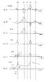
- the rotation of the crankshaft takes place from no later than 12 ° v. OT up to OT from about 200 rpm to the supply voltage Vdd (see Fig.3f ) from 0V to the working voltage, ie greater LVR (Low Voltage Reset). Due to the low startup speed, turning the motor is over OT and thus by the compression stroke with little effort possible.
- Vdd supply voltage
- LVR Low Voltage Reset
- the invention relates inter alia to a magneto ignition according to the principle of capacitor discharge, especially suitable for small engines, preferably hand-held small motors. Furthermore, the invention relates to an electric ignition method for internal combustion engines, which makes it possible to realize a spark at the 1st OT - passage and slow crankshaft speed (for example by 200 RPM or rpm). This effect occurs in particular when restarting the machine or after short breaks.
- a rotation angle of the crankshaft of preferably ⁇ 30 ° and low angular velocities of approximately 200 rpm suffice to achieve a spark and thus the start of the engine. Therefore, a minimum stroke (preferably ⁇ 20cm) and low force on the starter rope is required to put the machine into operation.
- the invention should be applicable to ignitions with analog controls as well as microelectronic controls.
- the iron core K is flooded with the legs Ka and Kb in each revolution periodically via the air gap L by a magnetic field Ba or Bb.
- the induced voltage level of the charging coil U1 and primary coil PS of the ignition transformer U5 are connected via the coupling circuit U7 ( Figure 4 ) are matched to the measuring range of the microcontroller U8 and thus can be easily scanned by the ADCs or the comparators of the microcontroller.
- the voltage level of the primary coil is checked.
- the voltage level of the primary coil at this time decides whether this is the first or the third half-wave ( Fig. 3a , Half-wave 10 or 14). Due to the described main flow change, the amplitude of the half-wave 14 is substantially larger and wider than that of the half-wave 10 (FIG. Fig. 3a ). Thus, the position of the pole wheel can be determined uniquely.
- the rotational speeds of the start region of the microcontroller can detect the speed, since the supply voltage is present over the entire revolution, and thus the period between coil signals can be detected and thereby the microcontroller Has speed information.
- a spark timing curve can be realized.
- the signals from the primary coil U5 of the ignition transformer are preferably used, if the levels of this coil are not sufficient, the signals of a single trigger or auxiliary coil U2 on the leg Kb ( Fig. 1 ,) are used.
- the primary voltage is detected indirectly, so that the voltage value then lies in the measuring range of the ADC or the comparators of the microcontroller.
- the ignition timing in the start and idle range can be varied.
- the solution is to remove the capacitor charge from the preceding engine run for the next start.
- no further capacitor discharge is necessary for a spark, but the ignition capacitor continues to be charged by the revolutions performed from the moment the stop switch is pressed to a stop. It should be noted that in the hot state ignitable mixture in the combustion chamber, so that the engine is quite startable with a strong spark in the first OT passage.
- the shutdown mode is achieved in the operating mode at least in the lower speed range, that the ignition switch is no longer activated, so no discharge of the ignition capacitor is more up to engine standstill, the ignition capacitor on reaching the engine standstill on sure charged a high value.
- start boost ignition energy available
- a variation to the described shutdown would be a complete abandonment of the discharge of the ignition capacitor during shutdown.
- Overloading of the ignition capacitor is to be prevented in this method by the use of voltage-limiting components, usually varistors.
- this method requires a larger set of materials and is therefore associated with higher costs, but can be implemented in software simpler.
- the gate of the ignition thyristor is grounded via a stop button or switch, thereby preventing the discharge of the ignition capacitor.
- a stop button or switch An example of such a principle is shown in FIG. 9 in FIG DE 197 36 032 A1 shown.
- the stop button U13 prevents the control of the semiconductor valve U4 by the microcontroller U8.
- the supply voltage must be built within a few degrees of angle using programmable logic controllers.
- the supply voltage Vdd of the microcontroller must therefore increase with the start within a few degrees and may fall back to below the operating voltage range due to the described position detection and early adjustment in the starting area after the spark.
- the power supply for the processor is supplied via the supply circuit U10 (FIG. Fig. 4 ) provided. This draws its energy directly from the 1st and 3rd half-wave of the charging coil, since the tap in front of the bridge rectifier G1 ( Figure 4 ) he follows. If no bridge rectifier is used, the corresponding half-waves can be coupled out directly from the charging coil.
- the supply voltage buildup which is important for the spark, occurs within the first half-wave of the charging coil.
- This first half-wave is very small in amplitude because it comes from the magnetic tributary ( Fig. 2d , River 1).
- the control must therefore be in operation within this weak half-wave (it suffices an angular range around the vertex of the charging coil) to recognize the position of the pole wheel and to operate the ignition switch.
- the microcontroller recognizes immediately after waking up when crossing a threshold Ux of the charging coil by scanning the primary coil level the Polradposition without knowing the history of the coil signals or their sequence of half-waves. Because of this strategy is among others possible to use for the supply voltage low capacitance buffer capacitors. As a result, the operating voltage builds up quickly in the starting speed range, then drops again quickly - but this is not relevant for determining the position in the starting area.
- Fig.3f The course of the supply voltage is in Fig.3f shown schematically.
- the processor At voltages above the LVR (Low Voltage Reset), the processor is ready for operation.
- the representation corresponds to a speed of about 200rpm.
- the time in which the operating voltage is built up at this speed corresponds to approximately 10 degrees of crankshaft rotation.
- the starter rope is approx. 0.8m long and enables 5..6 OT - passages.
Landscapes
- Engineering & Computer Science (AREA)
- Chemical & Material Sciences (AREA)
- Combustion & Propulsion (AREA)
- Mechanical Engineering (AREA)
- General Engineering & Computer Science (AREA)
- Signal Processing (AREA)
- Ignition Installations For Internal Combustion Engines (AREA)
Priority Applications (2)
| Application Number | Priority Date | Filing Date | Title |
|---|---|---|---|
| EP07117400A EP2042727A1 (fr) | 2007-09-27 | 2007-09-27 | Système d'allumage pour moteurs à combustion |
| US12/240,130 US8150606B2 (en) | 2007-09-27 | 2008-09-29 | Ignition system, easy to start for internal combustion engines |
Applications Claiming Priority (1)
| Application Number | Priority Date | Filing Date | Title |
|---|---|---|---|
| EP07117400A EP2042727A1 (fr) | 2007-09-27 | 2007-09-27 | Système d'allumage pour moteurs à combustion |
Publications (1)
| Publication Number | Publication Date |
|---|---|
| EP2042727A1 true EP2042727A1 (fr) | 2009-04-01 |
Family
ID=39040819
Family Applications (1)
| Application Number | Title | Priority Date | Filing Date |
|---|---|---|---|
| EP07117400A Withdrawn EP2042727A1 (fr) | 2007-09-27 | 2007-09-27 | Système d'allumage pour moteurs à combustion |
Country Status (2)
| Country | Link |
|---|---|
| US (1) | US8150606B2 (fr) |
| EP (1) | EP2042727A1 (fr) |
Cited By (4)
| Publication number | Priority date | Publication date | Assignee | Title |
|---|---|---|---|---|
| DE102010037478A1 (de) * | 2010-09-10 | 2012-03-15 | Prüfrex engineering e motion gmbh & co. kg | Elektrisches Brennkraftmaschinen-Zündsystem mit Ladespule |
| EP2789846A1 (fr) * | 2013-04-09 | 2014-10-15 | Honda Motor Co., Ltd. | Appareil de commande pour moteur à combustion interne sans batterie pourvu d'un embrayage centrifuge, d'un allumage à commande électronique et d'un papillon à commande électronique |
| DE102013016028B4 (de) * | 2012-10-31 | 2019-07-18 | Prüfrex engineering e motion gmbh & co. kg | Zündverfahren für eine Brennkraftmaschine sowie danach arbeitende Zündvorrichtung |
| FR3106378A1 (fr) * | 2020-01-20 | 2021-07-23 | Vitesco Technologies | Dispositif de démarrage de moteur |
Families Citing this family (7)
| Publication number | Priority date | Publication date | Assignee | Title |
|---|---|---|---|---|
| EP2020502A1 (fr) * | 2007-08-01 | 2009-02-04 | Prüfrex-Elektro-Apparatebau | Dispositif d'allumage électrique pour moteurs à combustion interne |
| CN101968021B (zh) * | 2009-07-28 | 2013-02-06 | 绍兴锋龙电机有限公司 | 用于小型汽油机的点火控制装置和抑制发动机反转的方法 |
| DE102013017008B4 (de) * | 2012-11-07 | 2018-06-14 | Prüfrex engineering e motion gmbh & co. kg | Drehrichtungserkennung einer Zündvorrichtung |
| DE102013020739B3 (de) * | 2013-12-10 | 2015-04-30 | Prüfrex engineering e motion gmbh & co. kg | Verfahren zum Betrieb einer Zündvorrichtung |
| CN105422357B (zh) * | 2015-12-22 | 2018-05-18 | 浙江锋龙电气股份有限公司 | 一种电感式汽油机防逆转点火装置 |
| CN106321323B (zh) * | 2016-08-29 | 2019-02-22 | 浙江锋龙电气股份有限公司 | 一种模拟与数字互补控制的汽油机点火方法及装置 |
| CN110546722A (zh) | 2017-04-20 | 2019-12-06 | 沃尔布罗有限责任公司 | 用于点火系统的层压堆叠件 |
Citations (11)
| Publication number | Priority date | Publication date | Assignee | Title |
|---|---|---|---|---|
| US3669086A (en) * | 1970-09-30 | 1972-06-13 | Motorola Inc | Solid state ignition system |
| US3739759A (en) * | 1972-02-04 | 1973-06-19 | Brunswick Corp | Rotation sensing pulse control generator for triggered ignition systems and the like |
| FR2639677A1 (fr) * | 1988-11-29 | 1990-06-01 | Labourier Robert | Dispositif recuperateur d'energie pour remise en marche du moteur du vehicule |
| US5069193A (en) * | 1989-07-29 | 1991-12-03 | Prufrex-Elektro-Apparatebau Inh. Helga Muller geb. Dutschke | Ignition process, arangement and apparatus for internal combustion engines with a magneto |
| US5513619A (en) * | 1995-01-30 | 1996-05-07 | R. E. Phelon Company, Inc. | Discharge ignition apparatus for internal combustion engine |
| JPH09140070A (ja) * | 1995-11-10 | 1997-05-27 | Denso Corp | 搭載用電源システム |
| EP1178208A2 (fr) * | 2000-08-02 | 2002-02-06 | Walbro Corporation | Système d'allumage par décharge de condensateur avec commande automatique d'avance et/ou commande de vitesse minimale |
| US20030089336A1 (en) * | 2001-11-13 | 2003-05-15 | Leo Kiessling | Microelectronic ignition method and ignition module with ignition spark burn-time prolonging for an internal combustion engine |
| EP1387084A2 (fr) * | 2002-08-02 | 2004-02-04 | DUCATI ENERGIA S.p.A. | Système d'allumage par induction avec contrôle numérique |
| EP1496249A1 (fr) * | 2002-04-12 | 2005-01-12 | Iida Denki Kogyo Co., Ltd. | Procede de commande de synchronisation d'allumage d'un moteur a combustion interne au moyen d'un dispositif d'allumage et d'un dispositif de commande de synchronisation d'allumage |
| DE102004059070A1 (de) * | 2004-08-20 | 2006-02-23 | Prüfrex-Elektro-Apparatebau Inh. Helga Müller, geb. Dutschke | Zündverfahren mit Stopschalter für Brennkraftmaschinen |
Family Cites Families (10)
| Publication number | Priority date | Publication date | Assignee | Title |
|---|---|---|---|---|
| SE425423B (sv) * | 1978-06-02 | 1982-09-27 | Svenska Electromagneter | Anordning vid elektroniska tendsystem, foretredesvis for forbrenningsmotorer |
| JPS63117177A (ja) * | 1986-10-31 | 1988-05-21 | Mitsubishi Electric Corp | 内燃機関点火装置 |
| US5878709A (en) * | 1997-08-19 | 1999-03-09 | Walbro Corporation | Ignition switch having a positive off and automatic on |
| US6581584B2 (en) * | 2000-05-18 | 2003-06-24 | Kokusan Denki Co., Ltd. | Ignition control system for internal combustion engine |
| US6691689B2 (en) * | 2000-10-13 | 2004-02-17 | Prüfrex-Elektro-Apparatebau, Inh. Helga Müller. Geb Dutschke | Rotation direction detector in ignition equipment of an internal combustion engine |
| US6588407B2 (en) * | 2001-06-06 | 2003-07-08 | R.E. Phelon Company, Inc. | Discharge ignition apparatus for internal combustion engine having automatic spark advance |
| US6761148B2 (en) * | 2001-09-03 | 2004-07-13 | Prufrex-Electro-Apparateubau, Inh. Helga Muller, Geb Dutschke | Electronic rotation speed-dependent control and/or diagnosis process for combustion engines |
| US7156075B2 (en) * | 2004-08-20 | 2007-01-02 | Prufrex-Elektro-Apparatebau, Inh. Helga Muller Geb Dutschke | Ignition method with stop switch for internal-combustion engines |
| JP4577031B2 (ja) * | 2005-02-03 | 2010-11-10 | 国産電機株式会社 | 内燃機関用点火装置 |
| US7069921B1 (en) * | 2005-02-09 | 2006-07-04 | Walbro Engine Management, L.L.C. | Control circuit for capacitor discharge ignition system |
-
2007
- 2007-09-27 EP EP07117400A patent/EP2042727A1/fr not_active Withdrawn
-
2008
- 2008-09-29 US US12/240,130 patent/US8150606B2/en active Active
Patent Citations (11)
| Publication number | Priority date | Publication date | Assignee | Title |
|---|---|---|---|---|
| US3669086A (en) * | 1970-09-30 | 1972-06-13 | Motorola Inc | Solid state ignition system |
| US3739759A (en) * | 1972-02-04 | 1973-06-19 | Brunswick Corp | Rotation sensing pulse control generator for triggered ignition systems and the like |
| FR2639677A1 (fr) * | 1988-11-29 | 1990-06-01 | Labourier Robert | Dispositif recuperateur d'energie pour remise en marche du moteur du vehicule |
| US5069193A (en) * | 1989-07-29 | 1991-12-03 | Prufrex-Elektro-Apparatebau Inh. Helga Muller geb. Dutschke | Ignition process, arangement and apparatus for internal combustion engines with a magneto |
| US5513619A (en) * | 1995-01-30 | 1996-05-07 | R. E. Phelon Company, Inc. | Discharge ignition apparatus for internal combustion engine |
| JPH09140070A (ja) * | 1995-11-10 | 1997-05-27 | Denso Corp | 搭載用電源システム |
| EP1178208A2 (fr) * | 2000-08-02 | 2002-02-06 | Walbro Corporation | Système d'allumage par décharge de condensateur avec commande automatique d'avance et/ou commande de vitesse minimale |
| US20030089336A1 (en) * | 2001-11-13 | 2003-05-15 | Leo Kiessling | Microelectronic ignition method and ignition module with ignition spark burn-time prolonging for an internal combustion engine |
| EP1496249A1 (fr) * | 2002-04-12 | 2005-01-12 | Iida Denki Kogyo Co., Ltd. | Procede de commande de synchronisation d'allumage d'un moteur a combustion interne au moyen d'un dispositif d'allumage et d'un dispositif de commande de synchronisation d'allumage |
| EP1387084A2 (fr) * | 2002-08-02 | 2004-02-04 | DUCATI ENERGIA S.p.A. | Système d'allumage par induction avec contrôle numérique |
| DE102004059070A1 (de) * | 2004-08-20 | 2006-02-23 | Prüfrex-Elektro-Apparatebau Inh. Helga Müller, geb. Dutschke | Zündverfahren mit Stopschalter für Brennkraftmaschinen |
Cited By (9)
| Publication number | Priority date | Publication date | Assignee | Title |
|---|---|---|---|---|
| DE102010037478A1 (de) * | 2010-09-10 | 2012-03-15 | Prüfrex engineering e motion gmbh & co. kg | Elektrisches Brennkraftmaschinen-Zündsystem mit Ladespule |
| DE102010037478B4 (de) * | 2010-09-10 | 2014-11-27 | Prüfrex engineering e motion gmbh & co. kg | Elektrisches Brennkraftmaschinen-Zündsystem mit Ladespule |
| DE102013016028B4 (de) * | 2012-10-31 | 2019-07-18 | Prüfrex engineering e motion gmbh & co. kg | Zündverfahren für eine Brennkraftmaschine sowie danach arbeitende Zündvorrichtung |
| EP2789846A1 (fr) * | 2013-04-09 | 2014-10-15 | Honda Motor Co., Ltd. | Appareil de commande pour moteur à combustion interne sans batterie pourvu d'un embrayage centrifuge, d'un allumage à commande électronique et d'un papillon à commande électronique |
| US9488146B2 (en) | 2013-04-09 | 2016-11-08 | Honda Motor Co., Ltd. | Control apparatus for general-purpose internal combustion engine |
| FR3106378A1 (fr) * | 2020-01-20 | 2021-07-23 | Vitesco Technologies | Dispositif de démarrage de moteur |
| WO2021148429A1 (fr) * | 2020-01-20 | 2021-07-29 | Vitesco Technologies GmbH | Dispositif de démarrage d'un moteur à combustion interne |
| CN114938655A (zh) * | 2020-01-20 | 2022-08-23 | 纬湃科技有限责任公司 | 内燃机起动装置 |
| CN114938655B (zh) * | 2020-01-20 | 2024-07-16 | 纬湃科技有限责任公司 | 内燃机起动装置 |
Also Published As
| Publication number | Publication date |
|---|---|
| US8150606B2 (en) | 2012-04-03 |
| US20090084368A1 (en) | 2009-04-02 |
Similar Documents
| Publication | Publication Date | Title |
|---|---|---|
| AT511612B1 (de) | Verfahren zum starten einer brennkraftmaschine | |
| US8150606B2 (en) | Ignition system, easy to start for internal combustion engines | |
| DE1639118B2 (de) | Zündsystem fur Verbrennungsmotoren | |
| EP2020502A1 (fr) | Dispositif d'allumage électrique pour moteurs à combustion interne | |
| DE2263244A1 (de) | Zuendanlage fuer brennkraftmaschinen | |
| DE3312412C2 (fr) | ||
| DE2362472A1 (de) | Zuendanlage mit magnetgenerator fuer brennkraftmaschinen | |
| DE3851955T2 (de) | Umkehrbarer motor. | |
| DE102015104941A1 (de) | Maschinenstartvorrichtung | |
| DE2922454A1 (de) | Anordnung eines elektronischen zuendsystems | |
| DE102013016028B4 (de) | Zündverfahren für eine Brennkraftmaschine sowie danach arbeitende Zündvorrichtung | |
| DE2205722C2 (de) | Kondensator-Zündanlage für Brennkraftmaschinen | |
| DE10232756B4 (de) | Mikroelektronisches Zündverfahren und Zündmodul mit Zündfunken-Brenndauerverlängerung für eine Brennkraftmaschine | |
| EP0443175A2 (fr) | Installation d'allumage pour moteurs à combustion | |
| DE1926952A1 (de) | Kondensatorentladungszuendung fuer Kolbenbrennkraftmaschinen | |
| DE19736032B4 (de) | Zündverfahren und Zündanordnung für Brennkraftmaschinen | |
| DE2233003A1 (de) | Anordnung an schwungradmagnetzuendapparaten mit kapazitiver zuendwirkung | |
| DE102004059070A1 (de) | Zündverfahren mit Stopschalter für Brennkraftmaschinen | |
| DE2712695A1 (de) | Zuendanlage fuer brennkraftmaschinen mit einem magnetgenerator | |
| DE2730002A1 (de) | Zuendanlage fuer brennkraftmaschinen mit einem magnetgenerator | |
| DE2623612C3 (de) | Hochspannungs-Kondensatorzündvorrichtung für Brennkraftmaschinen | |
| DE69403076T2 (de) | Zündsystem für eine innere brennkraftmaschine insbesondere für eine kettensäge oder vergleichbare maschine | |
| DE2833223A1 (de) | Kontaktfreie zuendvorrichtung fuer eine brennkraftmaschine | |
| DE2334610A1 (de) | Zuendanlage fuer brennkraftmaschinen | |
| DE2405382A1 (de) | Zuendanlage fuer brennkraftmaschinen mit einem magnetzuender |
Legal Events
| Date | Code | Title | Description |
|---|---|---|---|
| PUAI | Public reference made under article 153(3) epc to a published international application that has entered the european phase |
Free format text: ORIGINAL CODE: 0009012 |
|
| AK | Designated contracting states |
Kind code of ref document: A1 Designated state(s): AT BE BG CH CY CZ DE DK EE ES FI FR GB GR HU IE IS IT LI LT LU LV MC MT NL PL PT RO SE SI SK TR |
|
| AX | Request for extension of the european patent |
Extension state: AL BA HR MK RS |
|
| 17P | Request for examination filed |
Effective date: 20091001 |
|
| AKX | Designation fees paid |
Designated state(s): DE IT |
|
| 17Q | First examination report despatched |
Effective date: 20130314 |
|
| STAA | Information on the status of an ep patent application or granted ep patent |
Free format text: STATUS: THE APPLICATION HAS BEEN WITHDRAWN |
|
| 18W | Application withdrawn |
Effective date: 20130716 |