EP1387084A2 - Système d'allumage par induction avec contrôle numérique - Google Patents
Système d'allumage par induction avec contrôle numérique Download PDFInfo
- Publication number
- EP1387084A2 EP1387084A2 EP03012875A EP03012875A EP1387084A2 EP 1387084 A2 EP1387084 A2 EP 1387084A2 EP 03012875 A EP03012875 A EP 03012875A EP 03012875 A EP03012875 A EP 03012875A EP 1387084 A2 EP1387084 A2 EP 1387084A2
- Authority
- EP
- European Patent Office
- Prior art keywords
- microprocessor
- ignition
- engine
- voltage
- half wave
- Prior art date
- Legal status (The legal status is an assumption and is not a legal conclusion. Google has not performed a legal analysis and makes no representation as to the accuracy of the status listed.)
- Withdrawn
Links
Images


Classifications
-
- F—MECHANICAL ENGINEERING; LIGHTING; HEATING; WEAPONS; BLASTING
- F02—COMBUSTION ENGINES; HOT-GAS OR COMBUSTION-PRODUCT ENGINE PLANTS
- F02P—IGNITION, OTHER THAN COMPRESSION IGNITION, FOR INTERNAL-COMBUSTION ENGINES; TESTING OF IGNITION TIMING IN COMPRESSION-IGNITION ENGINES
- F02P3/00—Other installations
- F02P3/02—Other installations having inductive energy storage, e.g. arrangements of induction coils
- F02P3/04—Layout of circuits
-
- F—MECHANICAL ENGINEERING; LIGHTING; HEATING; WEAPONS; BLASTING
- F02—COMBUSTION ENGINES; HOT-GAS OR COMBUSTION-PRODUCT ENGINE PLANTS
- F02P—IGNITION, OTHER THAN COMPRESSION IGNITION, FOR INTERNAL-COMBUSTION ENGINES; TESTING OF IGNITION TIMING IN COMPRESSION-IGNITION ENGINES
- F02P5/00—Advancing or retarding ignition; Control therefor
- F02P5/04—Advancing or retarding ignition; Control therefor automatically, as a function of the working conditions of the engine or vehicle or of the atmospheric conditions
- F02P5/145—Advancing or retarding ignition; Control therefor automatically, as a function of the working conditions of the engine or vehicle or of the atmospheric conditions using electrical means
- F02P5/15—Digital data processing
-
- F—MECHANICAL ENGINEERING; LIGHTING; HEATING; WEAPONS; BLASTING
- F02—COMBUSTION ENGINES; HOT-GAS OR COMBUSTION-PRODUCT ENGINE PLANTS
- F02P—IGNITION, OTHER THAN COMPRESSION IGNITION, FOR INTERNAL-COMBUSTION ENGINES; TESTING OF IGNITION TIMING IN COMPRESSION-IGNITION ENGINES
- F02P1/00—Installations having electric ignition energy generated by magneto- or dynamo- electric generators without subsequent storage
- F02P1/04—Installations having electric ignition energy generated by magneto- or dynamo- electric generators without subsequent storage the generator being specially adapted for use with specific engine types, e.g. engines with V arrangement of cylinders
-
- F—MECHANICAL ENGINEERING; LIGHTING; HEATING; WEAPONS; BLASTING
- F02—COMBUSTION ENGINES; HOT-GAS OR COMBUSTION-PRODUCT ENGINE PLANTS
- F02P—IGNITION, OTHER THAN COMPRESSION IGNITION, FOR INTERNAL-COMBUSTION ENGINES; TESTING OF IGNITION TIMING IN COMPRESSION-IGNITION ENGINES
- F02P1/00—Installations having electric ignition energy generated by magneto- or dynamo- electric generators without subsequent storage
- F02P1/08—Layout of circuits
- F02P1/083—Layout of circuits for generating sparks by opening or closing a coil circuit
-
- F—MECHANICAL ENGINEERING; LIGHTING; HEATING; WEAPONS; BLASTING
- F02—COMBUSTION ENGINES; HOT-GAS OR COMBUSTION-PRODUCT ENGINE PLANTS
- F02P—IGNITION, OTHER THAN COMPRESSION IGNITION, FOR INTERNAL-COMBUSTION ENGINES; TESTING OF IGNITION TIMING IN COMPRESSION-IGNITION ENGINES
- F02P5/00—Advancing or retarding ignition; Control therefor
- F02P5/04—Advancing or retarding ignition; Control therefor automatically, as a function of the working conditions of the engine or vehicle or of the atmospheric conditions
- F02P5/145—Advancing or retarding ignition; Control therefor automatically, as a function of the working conditions of the engine or vehicle or of the atmospheric conditions using electrical means
- F02P5/15—Digital data processing
- F02P5/1502—Digital data processing using one central computing unit
- F02P5/1506—Digital data processing using one central computing unit with particular means during starting
-
- F—MECHANICAL ENGINEERING; LIGHTING; HEATING; WEAPONS; BLASTING
- F02—COMBUSTION ENGINES; HOT-GAS OR COMBUSTION-PRODUCT ENGINE PLANTS
- F02D—CONTROLLING COMBUSTION ENGINES
- F02D2250/00—Engine control related to specific problems or objectives
- F02D2250/06—Reverse rotation of engine
-
- F—MECHANICAL ENGINEERING; LIGHTING; HEATING; WEAPONS; BLASTING
- F02—COMBUSTION ENGINES; HOT-GAS OR COMBUSTION-PRODUCT ENGINE PLANTS
- F02D—CONTROLLING COMBUSTION ENGINES
- F02D2400/00—Control systems adapted for specific engine types; Special features of engine control systems not otherwise provided for; Power supply, connectors or cabling for engine control systems
- F02D2400/06—Small engines with electronic control, e.g. for hand held tools
-
- F—MECHANICAL ENGINEERING; LIGHTING; HEATING; WEAPONS; BLASTING
- F02—COMBUSTION ENGINES; HOT-GAS OR COMBUSTION-PRODUCT ENGINE PLANTS
- F02N—STARTING OF COMBUSTION ENGINES; STARTING AIDS FOR SUCH ENGINES, NOT OTHERWISE PROVIDED FOR
- F02N2250/00—Problems related to engine starting or engine's starting apparatus
- F02N2250/04—Reverse rotation of the engine
-
- F—MECHANICAL ENGINEERING; LIGHTING; HEATING; WEAPONS; BLASTING
- F02—COMBUSTION ENGINES; HOT-GAS OR COMBUSTION-PRODUCT ENGINE PLANTS
- F02P—IGNITION, OTHER THAN COMPRESSION IGNITION, FOR INTERNAL-COMBUSTION ENGINES; TESTING OF IGNITION TIMING IN COMPRESSION-IGNITION ENGINES
- F02P9/00—Electric spark ignition control, not otherwise provided for
- F02P9/002—Control of spark intensity, intensifying, lengthening, suppression
- F02P9/005—Control of spark intensity, intensifying, lengthening, suppression by weakening or suppression of sparks to limit the engine speed
-
- Y—GENERAL TAGGING OF NEW TECHNOLOGICAL DEVELOPMENTS; GENERAL TAGGING OF CROSS-SECTIONAL TECHNOLOGIES SPANNING OVER SEVERAL SECTIONS OF THE IPC; TECHNICAL SUBJECTS COVERED BY FORMER USPC CROSS-REFERENCE ART COLLECTIONS [XRACs] AND DIGESTS
- Y02—TECHNOLOGIES OR APPLICATIONS FOR MITIGATION OR ADAPTATION AGAINST CLIMATE CHANGE
- Y02T—CLIMATE CHANGE MITIGATION TECHNOLOGIES RELATED TO TRANSPORTATION
- Y02T10/00—Road transport of goods or passengers
- Y02T10/10—Internal combustion engine [ICE] based vehicles
- Y02T10/40—Engine management systems
Definitions
- This invention refers to an inductive ignition system with digital control for low powered internal combustion engines, for example for chain saws, lawnmowers, small motor vehicles and similar appliances; more in particular, the invention relates to a variable spark-advance ignition system of inductive type, capable of controlling the generation of the spark and the charging of the feeding circuit, in a differentiated mode, in relation to the variable speed rate of the engine, so as to obtain highly efficient ignition conditions, at the starting and during the running.
- the characteristics in terms of duration of the spark in an inductive ignition, and the characteristics in terms of efficiency are lighter than those of a capacitive ignition; this is especially evident at the starting up or at the low running or low rotational speed of the engine when the energy made available by the magnetic circuit of the voltage generator is still relatively limited.
- US-A-4.515.118 suggests the use of a microprocessor for controlling and calculating the ignition time during the positive half wave of the voltage generator, in relation to the rotational speed of the engine.
- the negative half wave of the voltage is used for charging the input capacitor of the microprocessor, while the positive half wave is used for generating the ignition spark, both at start-up and during the normal running of the engine; this solution involves limits in the choice of the angle of spark advance.
- the angle of spark advance in such types of ignition cannot exceed approximately 8-10°; in addition, at the start-up when the engine is operative at low rotational speeds, the energy supplied by the voltage generator during the negative voltage half waves, may not guarantee a correct and appropriate feeding of the control microprocessor.
- EP-A-0 727 578 proposes a solution capable of remedying the previously known problems of inductive ignitions, that is, of increasing the angle of the spark advance by means of an electronically controlled ignition system, such solution is susceptible of further improvements.
- EP-A-0 727 578 use is made of two angularly spaced apart phase sensors to determine the advance angle of the ignition at the start-up and during the normal operative conditions of the engine.
- the main object of the invention is therefore to optimise the performance and efficiency of a microprocessor-controlled electronic ignition system, particularly suitable for low powered internal combustion engines, which do not use specially dedicated reference sensors; in particular, during the start-up phase, the voltage generated by the ignition coil on the spark plug is maximised, by means of a solution which is independent of the structural and functional features of the voltage generator, of the type of rotor and magnets used, of the air gaps, and in general of the characteristics of the electromechanical system chosen, and of the variations in environmental temperature in which the entire system operates.
- a still further object of this invention is to provide an inductive ignition system with a digital control, whereby it is possible to operate with differentiated spark advance values at start-up and during the normal running conditions of the engine, with the possibility of controlling the spark advance of the engine, via software, by means of a specifically programmable microprocessor according to the requirements of the specific engine and by the particular application.
- the ignition system it is possible to position the time instant of generation of the spark, during the start-up phase of the engine, very close to the upper dead centre and within a few degrees, guaranteeing in all cases a sparking suitable for the ignition, and to be able to work, from the minimum to the maximum number of revolutions of the engine, with spark advances which can vary continuously, within a range of values of interest for these types of engines, for example ranging from 18° to 30°.
- a voltage generator constructed to generate alternate voltage signals comprising a first and a second end half-waves having a first polarity, and third intermediate half-wave having a second polarity opposite to the first one; according to a preferential embodiment of the invention it was also decided to work both on the positive intermediate half wave, and on the subsequent negative end half wave of each alternate voltage signal periodically supplied by the voltage generator, in order to optimise the spark advance conditions, with variations of the sparking time and condition considerably superior to those obtainable with conventional ignition systems.
- the instant of spark advance can be varied and controlled in a completely flexible and continuous mode throughout the entire range of degrees of extension of the central half wave, in which the current flowing in the primary winding of the ignition coil is high enough to guarantee the generation of the spark on the spark plug.
- the control of the instant of the spark advance during the central half wave of each alternate voltage signal produced by the generator is performed via software through an appropriate digital type microprocessor, according to the requirements of the specific engine.
- the ignition system consequently makes it possible to position the moment of generation of the spark, during the engine start-up phase, very close to the upper dead centre, for example in an angle of or less than 2-3°, thereby facilitating the starting up; thereafter, the engine may operate from the minimum engine speed, up to the maximum speed, with spark advances which can vary continuously within an interesting range of values for this type of engines.
- a choice of this kind enables the electronic ignition to exploit all the energy made available by the magnetic circuit, independently of all the conditions outside the ignition, the electromechanical system and the working temperature of the engine, thereby generating on the secondary winding of the ignition coil the maximum voltage that the system itself is able to supply for the ignition of the engine at the start-up.
- the ignition system comprising:
- the microprocessor is programmed to enable the charging of a capacitor of a feeding circuit for the microprocessor, during each alternated voltage signal of the generator, preventing the charging at the generation of a spark.
- the microprocessor is also programmed to recognize the speed and directional rotation of the engine, and to disable the generation of the spark in order to limit the maximum number of engine revolutions, or to prevent a possible reverse rotation of the engine, in relation to event signals fed to the microprocessor by the control circuit.
- the reference number 10 indicates a voltage generator comprising a magnetic rotor 11 having a magnetic pole system N, S, operatively connected to an internal combustion engine, and a stator 12 provided with a magnetic circuit linked to the pole-system of the rotor 11 and to an ignition coil 17, 18.
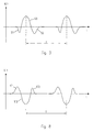
- the voltage generator 10 must be able to periodically generate, at each revolution of the rotor 11, an alternated voltage signal VL comprising two end half waves S1, S2, having a same polarity, and a central or intermediate half wave S3 having a polarity opposite to the first one.
- the magnet voltage generator 10 must be capable to sequentially generate alternate voltage signals each comprising, for example, a first negative end half wave S1 followed by a positive central half wave S3, of greater amplitude, and a subsequent second negative end half wave S2, as shown in the graph in figure 3 which represents the voltage signals VL1 produced by the generator 10 on the primary winding 17 of the ignition coil, in relation to time t, and in which T represents the period between two adjacent voltage signals, equivalent to the time required by the rotor to perform a revolution of 360°.
- the rotor 11 comprises a magnetic pole system N, S, provided by a permanent magnet 13 which extends radially; the magnet 13 is magnetized in a cross direction and has opposite magnetic polarities S and N between two pole pieces 14 and 15 extending peripherally on the edge of the rotor over an angle ranging for example from 30° to 40°.
- the stator 12 in turn comprises an upturned U-shaped magnetic yoke 16 provided by a pack of magnetic laminations having legs 16A and 16B extending towards the peripheral edge of the rotor 11 and defining a magnetic circuit linked to and interacting with the magnetic circuit of the rotor 11 provided by the pole pieces 14 and 15.
- An ignition coil 17, 18 is disposed around the leg 16B of the magnetic yoke 16 of the stator 12; the ignition coil comprises a primary winding 17 inductively coupled to a secondary winding 18 which powers an ignition spark plug CD, as shown in the wiring diagram of figure 2.
- the circulation of the current IL1 in the primary winding 17 of the ignition coil, as well as the instant of spark advance for generating the spark, are electronically controlled by means of a digital microprocessor Q1 forming part of a control circuit shown by the wiring diagram of figure 2, where references L1 and L2 have been used to indicate the inductances of the primary winding 17 and of the secondary winding 18 of the ignition coil, and reference CD the ignition spark plug; and in which reference VL1 and IL1 have been used to indicate the voltage signals produced by the generator 10, and respectively the current flowing in the primary winding 17 of the ignition coil.
- the inductive ignition system therefore comprises the voltage generator 10 and an ignition coil whose primary winding 17 is disposed in a microprocessor controlled circuit 20 for circulation of the ignition current.
- the electric circuit 20, in addition to the primary winding 17, comprises two electronic switches each having an internal or external diode for reverse circulation of the current; the electronic switches comprise for example two switches MOS1 and MOS2, whose Source - Drain circuits S-D are oppositely connected to each other by means of the source electrode S, and to a current measuring device such as the resistor R1 for the ignition current IR1; the resistor R1 makes it possible to control the ignition current IR1 flowing in the primary winding 17 and to determine the time instant at which to generate a spark in the ignition spark plug CD, during the start-up phase, and normal running of the engine.
- the diagram in figure 2 also comprises a second control circuit 21 for controlling the circulation of the ignition current IR1 in the circuit 20.
- control circuit 21 comprises a digital microprocessor Q1 having a first output U1 connected to the control electrodes G of the two electronic switches MOS1 and MOS2.
- the microprocessor Q1 is provided with a first input I1 and a second input I2 for event signals correlated to the phase and to the polarities of the voltage signals VL1 provided by the voltage generator 10 on the primary winding 17 of the ignition coil.
- a first input I1 of the microprocessor Q1 is connected to an end of the primary winding 17 by a first event signal generating means, schematically represented by a voltage divider R2 and R3, while a second input 12 of the microprocessor Q1 is connected to the other end of the primary winding 17 by means of a second event signal generating means correlated to the voltage VL1, comprising a voltage divider R4 and R5.
- a third signal input I3 of the microprocessor Q1 is connected to the resistors R6 and R7, necessary for biasing of the input I3; R7 is in turn connected to the measuring resistance R1 and possesses a value higher than that of the same measuring resistance R1.
- the microprocessor Q1 is also provided with a fourth input I4 connected to a feeding circuit 22.
- the feeding circuit 22 comprises a capacitor C1 connected, by means of a transistor J1 and a diode D1, to one side of the primary winding 17 of the ignition coil, and connected by means of the same transistor J1 and a diode D2 polarised in the opposite direction to the diode D1, to the other side of the primary winding 17.
- a resistor R8 and a Zener diode DZ1 stabilise the voltage of the capacitor C1 at a pre-established value.
- the base of the first transistor J1 is connected to the collector-emitter circuit of a second transistor J2, whose base is in turn connected to a second output U2 of the microprocessor Q1.
- start-up speed a number of revolutions per minute that can be set via software in the microprocessor Q1, called “start-up speed”, indicatively just a little below idling
- the system is powered on the central half wave S3 of VL1, positive in the case in question, always keeping the switches MOS1 and MOS2 open.
- the microprocessor Q1 recognises the second half wave S2 of VL1, it enables the conduction of the switches MOS1 and MOS2 so as to allow the flowing of a current IR1 which, from the primary winding 17 enters the MOS2, passes through the resistor R1 and returns onto the winding 17 through the MOS1.
- the current IR1 is measured depending on the voltage which is generated on the resistor R1, of a few tens of m.Ohm, which reflects on the input I3 through the two biasing resistors R6 and R7 of a few tens of K.Ohm.
- the microprocessor Q1 fitted with an internal analogical/digital converter, is therefore programmed with an appropriate algorithm to detect the instant in which the current IR1, in absolute value, reaches its maximum, and to emit at its output U1 a signal for the control electrodes G of the two switches MOS1 and MOS2, which will deactivate the latter, to open and consequently cause the generation of the spark with a practically fixed spark advance value, very close to the upper dead centre of the engine, depending exclusively upon the magnetic characteristics of the voltage generator, and devoid of any external influences.
- the system After having exceeded the cut-in speed of the engine, the system, in the example shown will use the two negative half waves S1 and S2 to power itself, and to maintain the capacitor C1 charged.
- the microprocessor Q1 detects the presence of the positive half wave S3 of VL1, figure 6, at an instant t1 it enables the conduction of the two electronic switches MOS1 and MOS2, re-opening them at an instant t2 to generate a spark on the spark plug CD in accordance with an ignition spark advance curve programmed via software in a memory of the microprocessor Q1, depending on the number of revolutions of the engine.
- the event signal of the positive half wave S3 of VL1 is taken as a phase reference for the spark advance curve.
- the system After starting up the engine, the system will consequently power itself during the two half waves S1, S2, which have a polarity opposite to that of the central half wave S3.
- the inductive ignition system according to the invention can also establish a limitation of the maximum number of revolutions for the engine, by opening the two electronic switches MOS1 and MOS2 only when the current IR1 which flows through the measuring resistor R1 is null, so as not to have induced voltages on the secondary winding 18 of the ignition coil.
- the event signals supplied to the two inputs I1 and I2 of the microprocessor Q1 are sensed by the latter as engine timing signals, which is an information sufficient to know at what number of revolutions the engine is rotating. Therefore when the microprocessor Q1 senses that the engine has reached a pre-established number of revolutions, stored in the microprocessor itself, the latter will actuate the opening of the two electronic switches MOS1 and MOS2 when the current flowing in the winding 17 of the ignition coil, is null, thereby avoiding the generation of a spark on the spark plug CD.
- the inductive ignition system can recognise the direction of rotation of the rotor and inhibit the generation of the spark by means of the same event signals supplied to the inputs I1 and 12 of the microprocessor Q1; in fact, as shown in figure 8, during the reverse rotation of the engine the polarities of the half waves S1 S2 and S3 of each voltage signal VL1, will be reversed, compared to the case of figure 3; in other words, with reference to the specific example, the microprocessor Q1, during the forward rotation of the engine, will detect a positive half wave S3 alternated by two negative half waves S1 and S2, while during the reverse rotation of the engine it will detect a negative half wave S'3 alternated by two positive half waves S'1 and S'2.
- the capacitor C1 is kept charged by the central half wave S3, or by the half waves S1, S2 of opposite polarity of the primary winding 17 of the ignition coil.
- the microprocessor Q1 must pilot the two electronic switches MOS1 and MOS2 exclusively with the voltage made available by the capacitor C1, which must therefore be high enough to ensure the satisfactory polarisation of the two electronic switches.
- the choice of working on the half wave which follows the central half wave that is to say on the second negative half wave S2 of the voltage VL1 in the case of figure 3, for generating the ignition spark, proves to be a winner in terms of supplying power to the microprocessor Q1 in that the capacitor C1 is charged by the central half wave S3 a few instants before enabling the conduction of the two electronic switches MOS1 and MOS2.
Landscapes
- Engineering & Computer Science (AREA)
- Chemical & Material Sciences (AREA)
- Combustion & Propulsion (AREA)
- Mechanical Engineering (AREA)
- General Engineering & Computer Science (AREA)
- Signal Processing (AREA)
- Theoretical Computer Science (AREA)
- Ignition Installations For Internal Combustion Engines (AREA)
Applications Claiming Priority (2)
| Application Number | Priority Date | Filing Date | Title |
|---|---|---|---|
| ITMI20021757 | 2002-08-02 | ||
| IT001757A ITMI20021757A1 (it) | 2002-08-02 | 2002-08-02 | Sistema di accensione induttiva con controllo digitale |
Publications (2)
| Publication Number | Publication Date |
|---|---|
| EP1387084A2 true EP1387084A2 (fr) | 2004-02-04 |
| EP1387084A3 EP1387084A3 (fr) | 2006-09-13 |
Family
ID=30012523
Family Applications (1)
| Application Number | Title | Priority Date | Filing Date |
|---|---|---|---|
| EP03012875A Withdrawn EP1387084A3 (fr) | 2002-08-02 | 2003-06-06 | Système d'allumage par induction avec contrôle numérique |
Country Status (6)
| Country | Link |
|---|---|
| EP (1) | EP1387084A3 (fr) |
| KR (1) | KR20040012528A (fr) |
| CN (1) | CN1475669A (fr) |
| BR (1) | BR0302539A (fr) |
| IT (1) | ITMI20021757A1 (fr) |
| TW (1) | TW200513590A (fr) |
Cited By (4)
| Publication number | Priority date | Publication date | Assignee | Title |
|---|---|---|---|---|
| WO2008006594A3 (fr) * | 2006-07-12 | 2008-03-27 | Phelon Euro Ab | Appareil et procédé pour un cadencement d'allumage pour un petit moteur à essence |
| EP2042727A1 (fr) * | 2007-09-27 | 2009-04-01 | Prüfrex-Elektro-Apparatebau | Système d'allumage pour moteurs à combustion |
| ITMI20131189A1 (it) * | 2013-07-16 | 2015-01-17 | Eldor Corp Spa | Sistema di accensione elettronica per un motore endotermico |
| US20210017946A1 (en) * | 2017-03-30 | 2021-01-21 | Mahle Electric Drives Japan Corporation | Engine ignition method and engine ignition device |
Families Citing this family (9)
| Publication number | Priority date | Publication date | Assignee | Title |
|---|---|---|---|---|
| CN100458139C (zh) * | 2004-12-17 | 2009-02-04 | 重庆三信电子有限公司 | 可进行编程和读数的数字点火器及其在线编程系统 |
| US8424501B2 (en) * | 2006-12-07 | 2013-04-23 | Contour Hardening, Inc. | Induction driven ignition system |
| CN101867257A (zh) * | 2010-07-13 | 2010-10-20 | 余姚市奥鑫电器有限公司 | 一种带有静电发生器的磁电机 |
| CN102996317A (zh) * | 2012-08-31 | 2013-03-27 | 无锡莱吉特信息科技有限公司 | 基于mems技术的发动机点火系统检测装置 |
| CN103423061B (zh) * | 2013-08-19 | 2016-05-18 | 同济大学 | 超高能火花放电系统 |
| CN105422357B (zh) * | 2015-12-22 | 2018-05-18 | 浙江锋龙电气股份有限公司 | 一种电感式汽油机防逆转点火装置 |
| DE112019001352T5 (de) * | 2018-03-15 | 2020-11-26 | Walbro Llc | Bestimmung und steuerung der motorphase |
| WO2020226910A1 (fr) | 2019-05-03 | 2020-11-12 | Walbro Llc | Système d'allumage de moteur à multiples événements d'allumage |
| WO2022167848A1 (fr) * | 2021-02-04 | 2022-08-11 | Shetty M Hariprasad | Système d'allumage à double énergie à transfert d'énergie ponctuel et procédé associé |
Citations (3)
| Publication number | Priority date | Publication date | Assignee | Title |
|---|---|---|---|---|
| US4188929A (en) | 1976-08-17 | 1980-02-19 | Robert Bosch Gmbh | Internal combustion engine magneto-type ignition system with electronically controlled spark advance |
| US4515118A (en) | 1983-07-13 | 1985-05-07 | Bosch Gmbh Robert | Magneto ignition system, particularly for one-cylinder internal combustion engines |
| EP0727578A2 (fr) | 1995-02-15 | 1996-08-21 | DUCATI ENERGIA S.p.A. | Système d'allumage inductif pour moteurs à combustion interne avec contrÔle électronique de l'avance à l'allumage |
Family Cites Families (4)
| Publication number | Priority date | Publication date | Assignee | Title |
|---|---|---|---|---|
| DE2261156C2 (de) * | 1972-12-14 | 1982-08-26 | Robert Bosch Gmbh, 7000 Stuttgart | Zündeinrichtung für Brennkraftmaschinen |
| DE3137550A1 (de) * | 1981-09-22 | 1983-03-31 | Robert Bosch Gmbh, 7000 Stuttgart | Zuendanlage fuer brennkraftmaschinen |
| JPH041342Y2 (fr) * | 1984-09-05 | 1992-01-17 | ||
| EP1298320A3 (fr) * | 2001-09-27 | 2004-10-20 | STMicroelectronics Pvt. Ltd | Système d'allumage par décharge de condensateur |
-
2002
- 2002-08-02 IT IT001757A patent/ITMI20021757A1/it unknown
-
2003
- 2003-06-06 EP EP03012875A patent/EP1387084A3/fr not_active Withdrawn
- 2003-07-29 BR BR0302539-0A patent/BR0302539A/pt not_active Application Discontinuation
- 2003-07-30 KR KR1020030052506A patent/KR20040012528A/ko not_active Withdrawn
- 2003-07-30 CN CNA031524214A patent/CN1475669A/zh active Pending
- 2003-10-06 TW TW092127663A patent/TW200513590A/zh unknown
Patent Citations (3)
| Publication number | Priority date | Publication date | Assignee | Title |
|---|---|---|---|---|
| US4188929A (en) | 1976-08-17 | 1980-02-19 | Robert Bosch Gmbh | Internal combustion engine magneto-type ignition system with electronically controlled spark advance |
| US4515118A (en) | 1983-07-13 | 1985-05-07 | Bosch Gmbh Robert | Magneto ignition system, particularly for one-cylinder internal combustion engines |
| EP0727578A2 (fr) | 1995-02-15 | 1996-08-21 | DUCATI ENERGIA S.p.A. | Système d'allumage inductif pour moteurs à combustion interne avec contrÔle électronique de l'avance à l'allumage |
Cited By (6)
| Publication number | Priority date | Publication date | Assignee | Title |
|---|---|---|---|---|
| WO2008006594A3 (fr) * | 2006-07-12 | 2008-03-27 | Phelon Euro Ab | Appareil et procédé pour un cadencement d'allumage pour un petit moteur à essence |
| EP2042727A1 (fr) * | 2007-09-27 | 2009-04-01 | Prüfrex-Elektro-Apparatebau | Système d'allumage pour moteurs à combustion |
| ITMI20131189A1 (it) * | 2013-07-16 | 2015-01-17 | Eldor Corp Spa | Sistema di accensione elettronica per un motore endotermico |
| WO2015008179A1 (fr) | 2013-07-16 | 2015-01-22 | Eldor Corporation S.P.A. | Système d'allumage électronique pour moteur endothermique |
| US20210017946A1 (en) * | 2017-03-30 | 2021-01-21 | Mahle Electric Drives Japan Corporation | Engine ignition method and engine ignition device |
| US11692502B2 (en) | 2017-03-30 | 2023-07-04 | Mahle International Gmbh | Engine ignition method and engine ignition device |
Also Published As
| Publication number | Publication date |
|---|---|
| TW200513590A (en) | 2005-04-16 |
| EP1387084A3 (fr) | 2006-09-13 |
| ITMI20021757A1 (it) | 2004-02-03 |
| KR20040012528A (ko) | 2004-02-11 |
| CN1475669A (zh) | 2004-02-18 |
| BR0302539A (pt) | 2004-08-24 |
Similar Documents
| Publication | Publication Date | Title |
|---|---|---|
| EP1387084A2 (fr) | Système d'allumage par induction avec contrôle numérique | |
| JP6518818B2 (ja) | 内燃機関用点火装置 | |
| US6940259B2 (en) | Generating device including magneto generator | |
| US4924831A (en) | Capacitor discharge ignition system with microprocessor timing control | |
| US5816221A (en) | Fuel injected rope-start engine system without battery | |
| US4150652A (en) | Contactless ignition system for internal combustion engine | |
| US3993031A (en) | Electronic magneto ignition system with engine speed limiting | |
| US4244337A (en) | Ignition system for internal combustion engines | |
| JPH0745865B2 (ja) | 内燃機関用点火装置 | |
| EP1691053B1 (fr) | Circuit de commande pour système d'allumage à décharge de condensateur | |
| JP3326977B2 (ja) | 内燃機関用電源装置 | |
| EP0727578B1 (fr) | Système d'allumage inductif pour moteurs à combustion interne avec contrôle électronique de l'avance à l'allumage | |
| US7028676B2 (en) | Inductive ignition system for internal combustion engines | |
| US5024204A (en) | Capacitive discharge ignition system with continuous timing advance | |
| US10634041B2 (en) | Ignition system for internal combustion engine | |
| US3439663A (en) | Transistor ignition system for gas engines | |
| JP3123294B2 (ja) | 内燃機関用無接点点火装置 | |
| JPH0219593Y2 (fr) | ||
| JPS6318779Y2 (fr) | ||
| JP4315308B2 (ja) | 内燃機関の無接点点火装置 | |
| JP3185686B2 (ja) | コンデンサ放電式内燃機関用点火装置 | |
| JPH0224953Y2 (fr) | ||
| JPS6120533Y2 (fr) | ||
| JPS5929775A (ja) | コンデンサ放電式内燃機関点火装置 | |
| JPH08338351A (ja) | コンデンサ放電式内燃機関用点火装置 |
Legal Events
| Date | Code | Title | Description |
|---|---|---|---|
| PUAI | Public reference made under article 153(3) epc to a published international application that has entered the european phase |
Free format text: ORIGINAL CODE: 0009012 |
|
| AK | Designated contracting states |
Kind code of ref document: A2 Designated state(s): AT BE BG CH CY CZ DE DK EE ES FI FR GB GR HU IE IT LI LU MC NL PT RO SE SI SK TR |
|
| AX | Request for extension of the european patent |
Extension state: AL LT LV MK |
|
| PUAL | Search report despatched |
Free format text: ORIGINAL CODE: 0009013 |
|
| AK | Designated contracting states |
Kind code of ref document: A3 Designated state(s): AT BE BG CH CY CZ DE DK EE ES FI FR GB GR HU IE IT LI LU MC NL PT RO SE SI SK TR |
|
| AX | Request for extension of the european patent |
Extension state: AL LT LV MK |
|
| STAA | Information on the status of an ep patent application or granted ep patent |
Free format text: STATUS: THE APPLICATION HAS BEEN WITHDRAWN |
|
| 18W | Application withdrawn |
Effective date: 20070112 |