EP2042800B2 - Feu de véhicule et son procédé de fabrication - Google Patents
Feu de véhicule et son procédé de fabrication Download PDFInfo
- Publication number
- EP2042800B2 EP2042800B2 EP08016908.9A EP08016908A EP2042800B2 EP 2042800 B2 EP2042800 B2 EP 2042800B2 EP 08016908 A EP08016908 A EP 08016908A EP 2042800 B2 EP2042800 B2 EP 2042800B2
- Authority
- EP
- European Patent Office
- Prior art keywords
- area
- coating
- outer lens
- vehicle light
- light
- Prior art date
- Legal status (The legal status is an assumption and is not a legal conclusion. Google has not performed a legal analysis and makes no representation as to the accuracy of the status listed.)
- Ceased
Links
Images

Classifications
-
- F—MECHANICAL ENGINEERING; LIGHTING; HEATING; WEAPONS; BLASTING
- F21—LIGHTING
- F21V—FUNCTIONAL FEATURES OR DETAILS OF LIGHTING DEVICES OR SYSTEMS THEREOF; STRUCTURAL COMBINATIONS OF LIGHTING DEVICES WITH OTHER ARTICLES, NOT OTHERWISE PROVIDED FOR
- F21V3/00—Globes; Bowls; Cover glasses
- F21V3/04—Globes; Bowls; Cover glasses characterised by materials, surface treatments or coatings
-
- F—MECHANICAL ENGINEERING; LIGHTING; HEATING; WEAPONS; BLASTING
- F21—LIGHTING
- F21S—NON-PORTABLE LIGHTING DEVICES; SYSTEMS THEREOF; VEHICLE LIGHTING DEVICES SPECIALLY ADAPTED FOR VEHICLE EXTERIORS
- F21S41/00—Illuminating devices specially adapted for vehicle exteriors, e.g. headlamps
- F21S41/20—Illuminating devices specially adapted for vehicle exteriors, e.g. headlamps characterised by refractors, transparent cover plates, light guides or filters
- F21S41/28—Cover glass
-
- F—MECHANICAL ENGINEERING; LIGHTING; HEATING; WEAPONS; BLASTING
- F21—LIGHTING
- F21S—NON-PORTABLE LIGHTING DEVICES; SYSTEMS THEREOF; VEHICLE LIGHTING DEVICES SPECIALLY ADAPTED FOR VEHICLE EXTERIORS
- F21S45/00—Arrangements within vehicle lighting devices specially adapted for vehicle exteriors, for purposes other than emission or distribution of light
- F21S45/10—Protection of lighting devices
-
- F—MECHANICAL ENGINEERING; LIGHTING; HEATING; WEAPONS; BLASTING
- F21—LIGHTING
- F21S—NON-PORTABLE LIGHTING DEVICES; SYSTEMS THEREOF; VEHICLE LIGHTING DEVICES SPECIALLY ADAPTED FOR VEHICLE EXTERIORS
- F21S45/00—Arrangements within vehicle lighting devices specially adapted for vehicle exteriors, for purposes other than emission or distribution of light
- F21S45/50—Waterproofing
-
- F—MECHANICAL ENGINEERING; LIGHTING; HEATING; WEAPONS; BLASTING
- F21—LIGHTING
- F21S—NON-PORTABLE LIGHTING DEVICES; SYSTEMS THEREOF; VEHICLE LIGHTING DEVICES SPECIALLY ADAPTED FOR VEHICLE EXTERIORS
- F21S43/00—Signalling devices specially adapted for vehicle exteriors, e.g. brake lamps, direction indicator lights or reversing lights
- F21S43/20—Signalling devices specially adapted for vehicle exteriors, e.g. brake lamps, direction indicator lights or reversing lights characterised by refractors, transparent cover plates, light guides or filters
- F21S43/26—Refractors, transparent cover plates, light guides or filters not provided in groups F21S43/235 - F21S43/255
Definitions
- the present invention relates to a vehicle light such as a vehicle headlight, an auxiliary headlight, a rear combination lamp, and the like, having an outer lens.
- the present invention also relates to a method for manufacturing the same.
- moisture may enter in the inside of the light during use.
- the entering moisture can adhere to the inner surface of the outer lens to mist it.
- the inner surface of the outer lens may be applied with an anti-fog coating.
- such an anti-fog coating should be transparent. Accordingly, when a completed product including the outer lens is observed, it is difficult to determine whether such a transparent anti-fog coating has been applied or not.
- conventional techniques include that a boundary line by a coating mask is to be formed on an outer lens at an unnoticeable position. After removing the coating mask, one can determine whether the transparent anti-fog coating has been applied or not by visually inspecting the presence or absence of the boundary line on the outer lens.
- the determination of whether the coating has been applied or not is required for other transparent coatings for surface treatment, such as a hard coating for an outer surface of an outer lens. If the determination has not been carried out, an uncoated product may be mixed in the group of coated products.
- DE 10 2004 046408 A1 was used as a basis for the preamble of the independent claims 1 and 6 and discloses a translucent component for a motor vehicle-head light which has a lighting effect changing region and a line for local influence of lighting characteristics of the component, where the region and line are manufactured by a laser process.
- the component has a lighting effect changing region and line for local influence of lighting characteristics of the component.
- the region and line are manufactured by a laser process, which causes local matting of the headlight component against the remaining part of the component.
- the region and line are completely arranged within a material of the component in a three-dimensional format.
- a headlight with a translucent component for a motor vehicle and a method of producing lighting effect in a translucent component of a motor vehicle-headlight.
- DE 199 60 802 A1 discloses a vehicle lamp comprising a lens that includes an inner surface on which an antifogging coating film is formed and an outer surface on which a hard coating film is formed. It is preferable that the vehicle lamp further comprises a lamp body, wherein said lens further includes: a lens front portion; a peripheral wall portion formed at the outer peripheral edge of said lens front portion; and a seal leg portion formed at the leading end of said peripheral wall portion and fixed to said lamp body, and wherein the antifogging coating film and the hard coating film are formed on at least said lens front portion excluding said seal leg portion of said lens.
- WO 03/038335 A discloses an automotive lamp which, under unlighting conditions, can achieve harmonized and uniform appearance with a color of body and others, windows, parts and others, in addition to satisfactory function as a lamp under lighting conditions.
- An automotive lamp provided with a lamp chamber containing at least one light source in an interior thereof and having a light-emitting opening, is constructed such that the light-emitting opening of the lamp chamber has attached thereto a lamp cover which comprises a transparent cover body and a polarizing film applied to an inner surface of the cover body, the polarizing film having fine textured structures on a surface thereof.
- An automotive lamp which can achieve the highest ever appearance design quality and permits observation of a uniform surface appearance high in quality with the feeling of depth emphasized when the lamp is extinguished.
- An automotive lamp comprising a lamp chamber with a light source arranged therein and having a light-emitting opening, wherein a transparent lamp cover is mounted on the light-emitting opening of the lamp chamber, and the inner surface of the lamp cover includes a selective polarizing layer formed, in a predetermined pattern, with structure portions having a finely textured structural surface and non-structure portions not having such a textured structure.
- a vehicle light is provided with a simple configuration by which whether a coating such as an anti-fog coating, a hard coating for surface treatment, and the like has been applied or not can be easily determined. Furthermore, according to another aspect of the present invention, a method for manufacturing such a vehicle light can be provided.
- a vehicle light is provided as set forth in claim 1.
- the outer lens has a second area which is adjacent to the first area and is not subjected to texturing process, at least part of the second area being applied with the coating for surface treatment.
- the outer lens and the housing may be bonded to each other at a bonding area which may include at least part of, or all of, the first area and the second area of the outer lens.
- the coating for surface treatment may include an anti-fog coating for the inner surface of the outer lens and a hard coating for the outer surface of the outer lens.
- a method for manufacturing a vehicle light is provided as set forth in claim 5.
- the outer lens in the applying of the coating, may have a second area which is adjacent to the first area and is not subjected to texturing process and at least part of the first area and part of the second area are included in the area for coating.
- the manufacturing method according to the present invention may further include, after the applying of the coating and prior to the fixing of the outer lens to the housing, determining whether the outer lens is properly coated with the coating or not based on a state of the first area and the second area which have been coated or not.
- the determination of whether the outer lens is properly coated with the coating or not can be achieved by visually inspecting the state of the first area and the second area which have been coated or not.
- the determination of whether the outer lens is properly coated with the coating or not can be achieved by optically measuring any of a transparency and a reflectance of the first area and the second area which have been coated or not.
- the coating for surface treatment may include an anti-fog coating for the inner surface of the outer lens and a hard coating for the outer surface of the outer lens.
- the outer lens has the first area which is subjected to texturing process at the same time when the outer lens is molded or as a postprocess. Accordingly, at least part of the first area where texturing process has been applied is applied with the coating for surface treatment such as an anti-fog coating on the inner surface of the outer lens or a hard coating on the outer surface of the outer lens. In this case, the fine irregularities of the first area by texturing process are covered with the coating film to disappear. Namely, this can smoothen the surface of the first area of the outer lens which has been applied with the coating to provide a very flat and smooth surface at the first area.
- the coating for surface treatment such as an anti-fog coating on the inner surface of the outer lens or a hard coating on the outer surface of the outer lens.
- the fine irregularities of the first area by texturing process are covered with the coating film to disappear. Namely, this can smoothen the surface of the first area of the outer lens which has been applied with the coating to provide a very flat and smooth surface at the first area.
- the determining of whether the outer lens is properly coated or not can be easily achieved simply by visually inspecting the first area of the outer lens and determining whether the texturing processed surface can be observed, namely, whether the coating can properly cover the first area.
- the irregularities of the texturing processed surface can be smoothened.
- the optical characteristics including the transparency, the reflectance and the like of that portion may be changed.
- the outer lens can include the second area which is adjacent to the first area and is not subjected to texturing process, and part of the first area and the second area can be applied with the coating for surface treatment.
- the first area having been subjected to texturing process and the second area not having been subjected to texturing process are compared with each other with regard to the application of the coating for surface treatment. Accordingly, the determination of whether the coating has been present or not can be more easily achieved.
- the bonding area where the outer lens and the housing are bonded to each other may include at least part of, or all of, the first area and the second area of the outer lens.
- the first and second areas are positioned near the bonding area of the housing when assembled. Accordingly, when light from the light source of the vehicle light is reflected by the reflecting surface and pass through the outer lens, the light does not pass through the first area and/or the second area. This means that the illumination light can be projected with a predetermined light distribution pattern without any effect by the first area and/or the second area. Further, if the bonding area and its surroundings do not affect the light distribution pattern, part of or all of the first area and/or the second area can be located outside the bonding area.
- a vehicle light can be provided with a simple configuration by which whether a coating such as an anti-fog coating, a hard coating for surface treatment, and the like has been applied or not can be easily determined. Furthermore, according to the present invention, a method for manufacturing such a vehicle light can be provided.
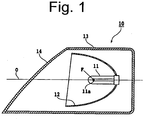
- Fig. 1 shows the configuration of a vehicle light in accordance with a first exemplary embodiment of the present invention.
- the vehicle light 10 can be configured as an automobile headlight.
- the vehicle light 10 can include: a bulb 11 serving as a light source; a reflecting surface 12 configured to reflect light from the bulb 11 to the front direction of the automobile (or in the illumination direction of light); a housing 13 configured to hermetically house the bulb 11 and the reflecting surface 12; an extension 17 covering the area near the open ends of the reflecting surface 12 and the housing 13 so that the housing 13 cannot be directly observed through the outer lens 14 when the vehicle light 10 is seen from the front side; and an outer lens 14 configured to hermetically close the front open end of the housing 13.
- the bulb 11 is one for use in a general automobile headlight or an auxiliary headlight.
- the light source can include an incandescent lamp, a halogen lamp, a discharge lamp such as a high intensity discharge lamp (HID lamp), an LED, and so on.
- the bulb 11 can be arranged almost horizontally so that its optical axis O is directed forward.
- the bulb 11 is fixedly held by a socket so that power can be fed therethrough to the bulb 11.
- the bulb 11 has its light emitting portion 11a extending and arranged along the optical axis O.
- the reflecting surface 12 is configured to reflect light from the bulb 11 to the front direction and is concave toward the front direction.
- the reflecting surface 12 can be composed of a revolved paraboloid.
- the revolved paraboloid of the reflecting surface 12 has its focal point F disposed at or near the light emitting portion 11a of the bulb 11. Furthermore, the revolved paraboloid has its longer axis disposed so as to coincide with the optical axis O extending toward the illumination direction.
- the revolved paraboloid may include a free curved surface derived from a paraboloid.
- the housing 13 can be formed of an opaque material so that light cannot pass therethrough.
- the housing 13 can house the bulb 11 and the reflecting surface 12 so as to hermetically surround them. Furthermore, the housing 13 is opened toward the front in the illumination direction so that light can emit from this open end of the housing 13.
- the outer lens 14 can be formed of a transparent material.
- the periphery of the outer lens 14 is hermetically bonded to the periphery of the opening of the housing 13. This configuration can prevent dusts and other fine materials from entering the light path extending from the reflecting surface 12 via the outer lens 14 to the outside.
- the outer lens 14 is coated with an anti-fog coating on its inner surface and a hard coating on its outer surface in this exemplary embodiment.
- the above configuration of the vehicle light is almost the same as that of the conventional vehicle light, but the vehicle light 10 of the present invention is different from the conventional vehicle light in the following points.
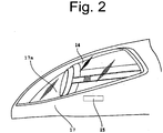
- the outer lens 14 includes a first coating determination portion 15 formed on its inner surface at a predetermined location, as shown in the side view of Fig. 2 .
- the outer lens 14 can further include a second coating determination portion 16 formed on its outer surface at a predetermined location, as shown in the side view of Fig. 3 .
- the first coating determination portion 15 can be disposed, as shown in Fig. 2 , on the inner surface of the outer lens 14 near the bonding area with the housing 13 so as to be partly located within the bonding area (in Fig. 2 , the portion 15 is shown with a solid line). Specifically, the first coating determination portion 15 can be disposed at a position facing to the extension 17 around a lighting chamber 17a provided with the bulb 11 and the reflecting surface 12, and at the same time, at a sideward and lower position near the periphery of the vehicle light 10. If the first coating determination portion 15 is disposed at a position directly facing to the lighting chamber 17a, it may be included within a light path of the light emitted from the vehicle light 10. In order to prevent it from hindering the light being emitted, it may be preferably located outside the light path. Accordingly, the first coating determination portion 15 is formed on the inner surface of the outer lens 14 at the position facing to the extension 17 near the bonding area with the housing 13.
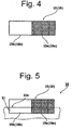
- the first coating determination portion 15 is formed in the form of a rectangle extending in one direction, as shown in Fig. 4 , and is divided into two areas, a first area 15a and a second area 15b divided at its longitudinal center.
- the first area 15a is subjected to texturing process on its surface.
- the texturing process may be achieved at the same time when the outer lens 14 is molded with a metal mold by, for example, injection molding, or as a postprocess after molding the outer lens 14.
- the texturing process may be achieved, for example, by the metal mold for the outer lens processed with sand blasting or etching at an area corresponding to the first area, or by directly sand blasting or etching the first area, though the present invention is not limited to these examples.
- the second area 15b is not processed, and accordingly, the surface of the second area 15b is substantially smooth.
- the above first coating determination portion 15 including the first area 15a and the second area 15b is simultaneously applied with the same anti-fog coating.
- the second coating determination portion 16 is disposed on the outer surface of the outer lens 14 near the bonding area with the housing 13 so as to be partly located within the bonding area at least.
- the second coating determination portion 16 is, as shown in Fig. 4 , formed in the form of a rectangle extending in one direction and is divided into two areas, a first area 16a and a second area 16b divided at its longitudinal center.
- the first area 16a is subjected to texturing process on its surface.
- the texturing process may be achieved at the same time when the outer lens 14 is molded with a metal mold or as a postprocess after molding the outer lens 14.
- the second area 16b is not processed, and accordingly, the surface of the second area 16b is substantially smooth.
- the above second coating determination portion 16 including the first area 16a and the second area 16b is simultaneously applied with the same hard coating.
- the vehicle light 10 in accordance with the present invention is configured as described above, and can emit light when the light emitting portion 11a of the bulb 11 is externally supplied with power.
- the light from the bulb 11 is reflected by the reflecting surface 12 to become parallel light and then is projected forward in the illumination direction through the outer lens 14.
- the first area 15a and the second area 15b of the first coating determination portion 15 are not applied with any coating before the inner surface of the outer lens 14 is applied with the anti-fog coating. Accordingly, when the first coating determination portion 15 is visually inspected, the texturing processed first area 15a can be observed as it is, meaning the irregularlities can be observed. The second area 15b is also observed as it is, i.e., the smoothly molded surface can be observed.
- the texturing processed surface of the first area 15a can be more clearly distinguished from other areas. Accordingly, when the texturing processed surface of the first area 15a is observed, it can be easily determined that the inner surface of the outer lens 14 has not been applied with the anti-fog coating.
- the inner surface of the outer lens 14 is applied with a transparent anti-fog coating so that the first area 15a and the second area 15b of the first coating determination portion 15 are also coated with the anti-fog coating.
- the texturing processed surface of the first area 15a is coated with the anti-fog coating to be smoothened.
- the second area 15b is also applied with the anti-fog coating, but observed so that it maintains the same smooth surface.
- the texturing processed surface of the first area 15a can be visually observed with difficulty, and the first area 15a can be observed to have the same surface state as that of the adjacent second area 15b. Accordingly, when the texturing processed surface of the first area 15a is not observed, it can be easily determined that the inner surface of the outer lens 14 has been properly applied with the anti-fog coating.
- the first area 16a and the second area 16b of the second coating determination portion 16 are not applied with a hard coating before the outer surface of the outer lens 14 is applied with the hard coating. Accordingly, when the second coating determination portion 16 is visually inspected, the texturing processed surface of the first area 16a can be observed as it is. The second area 16b is also observed as it is, i.e., the smoothly molded surface can be observed.
- the texturing processed surface of the first area 16a can be more clearly distinguished from other areas. Accordingly, when the texturing processed surface of the first area 15a is observed, it can be easily determined that the outer surface of the outer lens 14 has not been applied with the hard coating.
- the outer surface of the outer lens 14 is applied with a transparent hard coating, so that the first area 16a and the second area 16b of the second coating determination portion 16 are also coated with the hard coating.
- the texturing processed surface of the first area 16a is coated with the hard coating to be smoothened.
- the second area 16b is also applied with the hard coating, but observed so that it maintains the same smooth surface.
- the texturing processed surface of the first area 16a can be visually observed with difficulty, and the first area 16a can be observed to have the same surface state as that of the adjacent second area 16b. Accordingly, when the texturing processed surface of the first area 16a is not observed, it can be easily determined that the outer surface of the outer lens 14 has been properly applied with the hard coating.
- the smoothening of the texturing processed surface can be discriminated.
- the optical characteristics such as a transparency and a reflectance of the first area 15a (16a) can be measured before and after the application of coating. Then, the difference between before and after the application can be used for the determination of whether the texturing processed surface of the first area 15a (16a) has been applied with a coating or not. This can be automatically achieved with a certain system including a measuring apparatus, a CPU, and other peripheries (not shown).
- a coating such as an anti-fog coating, a hard coating for surface treatment, and the like has been applied on the inner surface and/or the outer surface of the outer lens or not can be easily determined with the simple configuration.
- Fig. 5 shows the configuration of main portions of a vehicle light according to a second exemplary embodiment of the present invention.
- the vehicle light 20 has almost the same configuration as that of the vehicle light 10 in the previous exemplary embodiment, except that the first coating determination portion 15 and the second coating determination portion 16 are partly covered with a mask 21 when applied with the coating.
- the mask 21 before the application of the coating the mask 21 is disposed such that the edge 21a of the mask 21 extends along the width center areas of the first area 15a (16a) and the second area 15b (16b) of the first coating determination portion 15 (or the second coating determination portion 16), as shown in Fig. 5 .
- the area covered with the mask 21 of the first coating determination portion 15 is not coated with the anti-fog (or hard) coating. Accordingly, the area covered with the mask 21 of, in particular, the first area 15a (16a) is not coated with the anti-fog (or hard) coating so that the texturing processed surface is still exposed on its surface.
- a boundary line between the coated area and not-coated area can be formed by the edge 21a of the mask 21 on the first coating determination portion 15 (or the second coating determination portion 16). Namely, this can provide the coated first area 15a, the non-coated first area 15a (still exposing its texturing processed surface), the coated second area 15b, and the non-coated second area 15b, and the boundary line between the coated areas and the non-coated areas. Accordingly, even if the area around the boundary line has been coated with the transparent coating, the texturing processed surface can be visually observed. This can facilitate the detection of the position of the first coating determination portion 15 (or the second coating determination portion 16) during the determination of whether the anti-fog (or hard) coating has been applied or not. Accordingly, the determination of whether the anti-fog (or hard) coating has been applied on the outer lens 14 or not can be achieved rapidly in a reliable manner.
- the coated areas and non-coated areas of the first area 15a (16a) and the second area 15b (16b) of the first coating determination portion 15 are measured and compared with one another. This can further facilitate the determination of whether the anti-fog (or hard) coating has been applied or not with improved accuracy.
- the first coating determination portion 15 and the second coating determination portion 16 include the respective second areas 15a and 16a.
- the present invention is not limited to these exemplary embodiments, and they may not include the second areas 15a and 16a.
- the first coating determination portion 15 and the second coating determination portion 16 are disposed near the bonding area with the housing 13, but the present invention is not limited to these exemplary embodiments. Alternatively, they can be disposed areas that cannot be visually observed with ease from outside or areas that does not badly affect the light distribution of light from the bulb 11, the reflecting surface 12, and the like.
- the coating for surface treatment includes an anti-fog coating and a hard coating, but the present invention is not limited to these exemplary embodiments.
- the present invention can be applied to any transparent coatings for surface treatment for which it is difficult to be discriminated after coated.
- the vehicle light serves as a headlight for an automobile, but the present invention is not limited to these exemplary embodiments. Examples thereof may include an auxiliary headlight, a signal light, and other type vehicle light.
- a vehicle light can be provided with a simple configuration by which whether a coating such as an anti-fog coating, a hard coating for surface treatment, and the like has been applied or not can be easily determined. Furthermore, a method for manufacturing such a vehicle light can be provided.
Landscapes
- Engineering & Computer Science (AREA)
- General Engineering & Computer Science (AREA)
- Non-Portable Lighting Devices Or Systems Thereof (AREA)
Claims (9)
- Feu de véhicule (10, 20) comprenant :un boîtier (13) comportant une extrémité ouverte avant, ouverte dans une direction d'éclairage ;une source de lumière (11) disposée dans le boîtier (13) ;une surface réfléchissante (12) disposée dans le boîtier (13), agencée pour réfléchir de la lumière provenant de la source de lumière (11) dans la direction d'éclairage, la surface réfléchissante (12) étant concave dans le sens de la direction d'éclairage ; etune lentille extérieure (14) disposée en face de la surface réfléchissante (12) de façon à fermer hermétiquement l'extrémité ouverte avant du boîtier (13), la lentille extérieure (14) comportant une surface intérieure et une surface extérieure sur au moins l'une desquelles est appliqué un revêtement pour un traitement de surface,la lentille extérieure (14) comporte en outre une première région (15a, 16a) qui a été soumise à un traitement de texture sur l'une de sa surface intérieure et de sa surface extérieure, au moins une partie de la première région (15a, 16a) ayant reçu l'application d'un revêtement pour un traitement de surface ; etla lentille extérieure (14) comporte une deuxième région (15b, 16b) qui est adjacente à la première région (15a, 16a) et n'a pas été soumise au traitement de texture, au moins une partie de la deuxième région (15b, 16b) ayant reçu l'application du revêtement pour le traitement de surface ;caractérisé en ce quela lentille extérieure (14) et le boîtier (13) sont liés l'un à l'autre au niveau d'une région de liaison qui inclut au moins une partie, ou la totalité, de la première région (15a, 16a) et de la deuxième région (15b, 16b) de la lentille extérieure (14).
- Feu de véhicule (10, 20) selon la revendication 1, caractérisé en ce que le revêtement pour le traitement de surface est un revêtement antibuée pour la surface intérieure de la lentille extérieure.
- Feu de véhicule (10, 20) selon la revendication 1 ou 2, caractérisé en ce que le revêtement pour le traitement de surface est un revêtement dur pour la surface extérieure de la lentille extérieure.
- Procédé de fabrication d'un feu de véhicule (10, 20), comprenant :former une lentille extérieure (14) comportant une surface intérieure et une surface extérieure avec une première région (15a) ayant été soumise à un traitement de texture sur au moins sa surface intérieure ;appliquer un revêtement pour un traitement de surface sur la surface intérieure de la lentille extérieure (14) à proximité d'une région de liaison avec le boîtier (13) de façon à ce qu'il soit partiellement situé dans la région de liaison, la région de liaison comprenant au moins une partie, ou la totalité, de la première région (15a) ; etfixer la lentille extérieure (14) à un boîtier (13) d'un feu de véhicule (10, 20), dans lequeldans l'application du revêtement, au moins une partie de la première région (15a) de la lentille extérieure (14) reçoit l'application du revêtement de traitement de surface ; etdans l'application du revêtement, la lentille extérieure (14) comporte une deuxième région (15b) qui est adjacente à la première région (15a) et n'a pas été soumise à un traitement de texture et au moins une partie de la première région (15a) et une partie de la deuxième région (15b) sont incluses dans la région de liaison.
- Procédé de fabrication d'un feu de véhicule (10, 20) selon la revendication 4, caractérisé en ce qu'il comprend en outre, après l'application du revêtement et avant de fixer la lentille extérieure (14) au boîtier (13), le fait de déterminer si la lentille extérieure (14) est correctement revêtue du revêtement ou non sur la base de l'état de la première région (15a) qui a été revêtue ou non.
- Procédé de fabrication d'un feu de véhicule (10, 20) selon la revendication 4, caractérisé en ce qu'il comprend en outre, après l'application du revêtement et avant la fixation de la lentille extérieure (14) au boîtier (13), le fait de déterminer si la lentille extérieure (14) est correctement revêtue du revêtement ou pas sur la base de l'état de la première région (15a) et/ou de la deuxième région (15b) qui ont été revêtues ou pas.
- Procédé de fabrication d'un feu de véhicule selon la revendication 5 ou 6, caractérisé en ce que la détermination si la lentille extérieure (14) est correctement revêtue du revêtement est obtenue en inspectant visuellement l'état de la première région (15a) et de la deuxième région (15b) qui ont été revêtues ou pas.
- Procédé de fabrication d'un feu de véhicule selon la revendication 5 ou 6, caractérisé en ce que la détermination si la lentille extérieure (14) est correctement revêtue du revêtement est obtenue en mesurant optiquement l'une de la transparence et de la réflectance de la première région (15a) et de la deuxième région (15b) qui ont été de revêtues ou pas.
- Procédé de fabrication d'un feu de véhicule selon l'une quelconque des revendications 4 à 8, caractérisé en ce que le revêtement pour le traitement de surface est un revêtement antibuée pour la surface intérieure de la lentille extérieure (14) .
Applications Claiming Priority (1)
| Application Number | Priority Date | Filing Date | Title |
|---|---|---|---|
| JP2007254541A JP4512904B2 (ja) | 2007-09-28 | 2007-09-28 | 車両用灯具の製造方法 |
Publications (4)
| Publication Number | Publication Date |
|---|---|
| EP2042800A2 EP2042800A2 (fr) | 2009-04-01 |
| EP2042800A3 EP2042800A3 (fr) | 2010-04-28 |
| EP2042800B1 EP2042800B1 (fr) | 2014-11-12 |
| EP2042800B2 true EP2042800B2 (fr) | 2018-04-11 |
Family
ID=40070568
Family Applications (1)
| Application Number | Title | Priority Date | Filing Date |
|---|---|---|---|
| EP08016908.9A Ceased EP2042800B2 (fr) | 2007-09-28 | 2008-09-25 | Feu de véhicule et son procédé de fabrication |
Country Status (3)
| Country | Link |
|---|---|
| US (1) | US7954986B2 (fr) |
| EP (1) | EP2042800B2 (fr) |
| JP (1) | JP4512904B2 (fr) |
Families Citing this family (3)
| Publication number | Priority date | Publication date | Assignee | Title |
|---|---|---|---|---|
| DE102014202851A1 (de) * | 2014-02-17 | 2015-08-20 | Volkswagen Aktiengesellschaft | Beleuchtungseinrichtung für ein Fahrzeug und Fahrzeug mit einer Beleuchtungseinrichtung |
| JP6933961B2 (ja) * | 2017-11-17 | 2021-09-08 | 株式会社小糸製作所 | 2色成形レンズ |
| WO2025183080A1 (fr) * | 2024-02-29 | 2025-09-04 | 市光工業株式会社 | Lentille de véhicule, phare de véhicule et procédé de fabrication de lentille de véhicule |
Citations (1)
| Publication number | Priority date | Publication date | Assignee | Title |
|---|---|---|---|---|
| FR2799527A1 (fr) † | 1999-10-07 | 2001-04-13 | Koito Mfg Co Ltd | Lampe de vehicule comportant une glace munie de marques, et son procede de fabrication |
Family Cites Families (8)
| Publication number | Priority date | Publication date | Assignee | Title |
|---|---|---|---|---|
| EP0666993B1 (fr) * | 1992-10-29 | 1999-06-09 | Minnesota Mining And Manufacturing Company | Corps multicouche reflecteur faconnable |
| JPH0650113U (ja) * | 1992-12-08 | 1994-07-08 | 市光工業株式会社 | 自動車用前照灯 |
| US5931566A (en) * | 1995-10-12 | 1999-08-03 | Valeo Sylvania L.L.C. | Colored and decorative lighting |
| JP2000182410A (ja) * | 1998-12-17 | 2000-06-30 | Koito Mfg Co Ltd | 車両用灯具 |
| JP3926940B2 (ja) | 1998-12-17 | 2007-06-06 | 株式会社小糸製作所 | 車両用灯具のレンズ表面処理方法 |
| DE60229064D1 (de) * | 2001-10-31 | 2008-11-06 | 3M Innovative Properties Co | Kraftfahrzeuglampe |
| US7175293B2 (en) * | 2001-11-02 | 2007-02-13 | 3M Innovative Properties Company | Decorative article and vehicular lamp |
| DE102004046408A1 (de) * | 2004-09-24 | 2006-03-30 | Automotive Lighting Reutlingen Gmbh | Komponente eines Kraftfahrzeug-Scheinwerfers, Front-Scheinwerfer für ein Kraftfahrzeug sowie Verfahren zur Herstellung einer Scheinwerfer-Komponente |
-
2007
- 2007-09-28 JP JP2007254541A patent/JP4512904B2/ja not_active Expired - Fee Related
-
2008
- 2008-09-25 EP EP08016908.9A patent/EP2042800B2/fr not_active Ceased
- 2008-09-29 US US12/240,095 patent/US7954986B2/en active Active
Patent Citations (1)
| Publication number | Priority date | Publication date | Assignee | Title |
|---|---|---|---|---|
| FR2799527A1 (fr) † | 1999-10-07 | 2001-04-13 | Koito Mfg Co Ltd | Lampe de vehicule comportant une glace munie de marques, et son procede de fabrication |
Also Published As
| Publication number | Publication date |
|---|---|
| EP2042800B1 (fr) | 2014-11-12 |
| US7954986B2 (en) | 2011-06-07 |
| EP2042800A3 (fr) | 2010-04-28 |
| EP2042800A2 (fr) | 2009-04-01 |
| JP4512904B2 (ja) | 2010-07-28 |
| JP2009087650A (ja) | 2009-04-23 |
| US20090122569A1 (en) | 2009-05-14 |
Similar Documents
| Publication | Publication Date | Title |
|---|---|---|
| JP6802531B2 (ja) | レーザーセンサー及び外装部品の製造方法 | |
| CN105486686B (zh) | 涂漆表面光洁度的基于led的检查 | |
| EP2042800B2 (fr) | Feu de véhicule et son procédé de fabrication | |
| CN112317271A (zh) | 透明的车辆零件的制造方法 | |
| US7453563B2 (en) | Device and method for detecting scratches | |
| CN108204568A (zh) | 车辆用灯 | |
| EP3463980B1 (fr) | Ensemble lampe pour véhicule | |
| JP2002133920A (ja) | 自動車用の照明または表示装置 | |
| US12115707B2 (en) | Method for manufacturing a translucent or transparent vehicle part | |
| US10760764B2 (en) | Partial metallization of molded part using ablation | |
| CN112781006A (zh) | 透明车辆部件的制造方法 | |
| EP0732534B1 (fr) | Feu de signalisation, notamment pour véhicule automobile, produisant un faisceau d'une teinte donnée et présentant une autre teinte lorsqu'il est éteint, et procédé de fabrication du voyant d'un tel feu | |
| JP4793347B2 (ja) | 車両用灯具、その被膜有無識別方法、およびそのためのアウターレンズ部品 | |
| WO2024059506A1 (fr) | Effets de motif et d'éclairage diffusifs améliorés sur des panneaux de surface d'automobile | |
| US11305312B2 (en) | Method for manufacturing a transparent vehicle part | |
| US12338965B2 (en) | Enhanced diffusive lighting and pattern effects over automotive surface panels | |
| WO2007125340A1 (fr) | Dispositif d'inspection de surfaces optiquement complexes | |
| JP2019096462A (ja) | 樹脂成形品および車両用灯具 | |
| JP4040306B2 (ja) | 灯具及びリフレクタ製造方法 | |
| JP4176302B2 (ja) | 検査装置 | |
| KR101664566B1 (ko) | 스팟 램프를 이용한 선글라스 케이스 무드 조명 | |
| JP2010060411A (ja) | 照明装置および検査方法 | |
| JP2001195911A (ja) | 車両用灯具 | |
| JP2003272412A (ja) | 車両用灯具 | |
| JPH0511208U (ja) | 車両用灯具 |
Legal Events
| Date | Code | Title | Description |
|---|---|---|---|
| PUAI | Public reference made under article 153(3) epc to a published international application that has entered the european phase |
Free format text: ORIGINAL CODE: 0009012 |
|
| AK | Designated contracting states |
Kind code of ref document: A2 Designated state(s): AT BE BG CH CY CZ DE DK EE ES FI FR GB GR HR HU IE IS IT LI LT LU LV MC MT NL NO PL PT RO SE SI SK TR |
|
| AX | Request for extension of the european patent |
Extension state: AL BA MK RS |
|
| PUAL | Search report despatched |
Free format text: ORIGINAL CODE: 0009013 |
|
| AK | Designated contracting states |
Kind code of ref document: A3 Designated state(s): AT BE BG CH CY CZ DE DK EE ES FI FR GB GR HR HU IE IS IT LI LT LU LV MC MT NL NO PL PT RO SE SI SK TR |
|
| AX | Request for extension of the european patent |
Extension state: AL BA MK RS |
|
| 17P | Request for examination filed |
Effective date: 20101028 |
|
| AKX | Designation fees paid |
Designated state(s): DE FR GB |
|
| 17Q | First examination report despatched |
Effective date: 20110519 |
|
| GRAP | Despatch of communication of intention to grant a patent |
Free format text: ORIGINAL CODE: EPIDOSNIGR1 |
|
| INTG | Intention to grant announced |
Effective date: 20140415 |
|
| GRAS | Grant fee paid |
Free format text: ORIGINAL CODE: EPIDOSNIGR3 |
|
| GRAA | (expected) grant |
Free format text: ORIGINAL CODE: 0009210 |
|
| AK | Designated contracting states |
Kind code of ref document: B1 Designated state(s): DE FR GB |
|
| REG | Reference to a national code |
Ref country code: GB Ref legal event code: FG4D |
|
| REG | Reference to a national code |
Ref country code: DE Ref legal event code: R096 Ref document number: 602008035268 Country of ref document: DE Effective date: 20141224 |
|
| REG | Reference to a national code |
Ref country code: DE Ref legal event code: R026 Ref document number: 602008035268 Country of ref document: DE |
|
| PLBI | Opposition filed |
Free format text: ORIGINAL CODE: 0009260 |
|
| 26 | Opposition filed |
Opponent name: VALEO VISION Effective date: 20150811 |
|
| PLAX | Notice of opposition and request to file observation + time limit sent |
Free format text: ORIGINAL CODE: EPIDOSNOBS2 |
|
| REG | Reference to a national code |
Ref country code: FR Ref legal event code: PLFP Year of fee payment: 8 |
|
| PLBB | Reply of patent proprietor to notice(s) of opposition received |
Free format text: ORIGINAL CODE: EPIDOSNOBS3 |
|
| REG | Reference to a national code |
Ref country code: FR Ref legal event code: PLFP Year of fee payment: 9 |
|
| PLAB | Opposition data, opponent's data or that of the opponent's representative modified |
Free format text: ORIGINAL CODE: 0009299OPPO |
|
| R26 | Opposition filed (corrected) |
Opponent name: VALEO VISION Effective date: 20150811 |
|
| REG | Reference to a national code |
Ref country code: FR Ref legal event code: PLFP Year of fee payment: 10 |
|
| REG | Reference to a national code |
Ref country code: DE Ref legal event code: R079 Ref document number: 602008035268 Country of ref document: DE Free format text: PREVIOUS MAIN CLASS: F21S0008100000 Ipc: F21S0043000000 |
|
| PUAH | Patent maintained in amended form |
Free format text: ORIGINAL CODE: 0009272 |
|
| STAA | Information on the status of an ep patent application or granted ep patent |
Free format text: STATUS: PATENT MAINTAINED AS AMENDED |
|
| 27A | Patent maintained in amended form |
Effective date: 20180411 |
|
| AK | Designated contracting states |
Kind code of ref document: B2 Designated state(s): DE FR GB |
|
| REG | Reference to a national code |
Ref country code: DE Ref legal event code: R102 Ref document number: 602008035268 Country of ref document: DE |
|
| REG | Reference to a national code |
Ref country code: FR Ref legal event code: PLFP Year of fee payment: 11 |
|
| PGFP | Annual fee paid to national office [announced via postgrant information from national office to epo] |
Ref country code: GB Payment date: 20230803 Year of fee payment: 16 |
|
| PGFP | Annual fee paid to national office [announced via postgrant information from national office to epo] |
Ref country code: FR Payment date: 20230808 Year of fee payment: 16 Ref country code: DE Payment date: 20230802 Year of fee payment: 16 |
|
| REG | Reference to a national code |
Ref country code: DE Ref legal event code: R119 Ref document number: 602008035268 Country of ref document: DE |
|
| GBPC | Gb: european patent ceased through non-payment of renewal fee |
Effective date: 20240925 |
|
| PG25 | Lapsed in a contracting state [announced via postgrant information from national office to epo] |
Ref country code: DE Free format text: LAPSE BECAUSE OF NON-PAYMENT OF DUE FEES Effective date: 20250401 |
|
| PG25 | Lapsed in a contracting state [announced via postgrant information from national office to epo] |
Ref country code: GB Free format text: LAPSE BECAUSE OF NON-PAYMENT OF DUE FEES Effective date: 20240925 |
|
| PG25 | Lapsed in a contracting state [announced via postgrant information from national office to epo] |
Ref country code: FR Free format text: LAPSE BECAUSE OF NON-PAYMENT OF DUE FEES Effective date: 20240930 |