EP2043079A2 - Videoanzeigegerät mit dynamischer Helligkeitssteuerung des Backlights - Google Patents
Videoanzeigegerät mit dynamischer Helligkeitssteuerung des Backlights Download PDFInfo
- Publication number
- EP2043079A2 EP2043079A2 EP08015642A EP08015642A EP2043079A2 EP 2043079 A2 EP2043079 A2 EP 2043079A2 EP 08015642 A EP08015642 A EP 08015642A EP 08015642 A EP08015642 A EP 08015642A EP 2043079 A2 EP2043079 A2 EP 2043079A2
- Authority
- EP
- European Patent Office
- Prior art keywords
- light
- luminance
- video signal
- apl
- input video
- Prior art date
- Legal status (The legal status is an assumption and is not a legal conclusion. Google has not performed a legal analysis and makes no representation as to the accuracy of the status listed.)
- Withdrawn
Links
Images



Classifications
-
- G—PHYSICS
- G09—EDUCATION; CRYPTOGRAPHY; DISPLAY; ADVERTISING; SEALS
- G09G—ARRANGEMENTS OR CIRCUITS FOR CONTROL OF INDICATING DEVICES USING STATIC MEANS TO PRESENT VARIABLE INFORMATION
- G09G3/00—Control arrangements or circuits, of interest only in connection with visual indicators other than cathode-ray tubes
- G09G3/20—Control arrangements or circuits, of interest only in connection with visual indicators other than cathode-ray tubes for presentation of an assembly of a number of characters, e.g. a page, by composing the assembly by combination of individual elements arranged in a matrix no fixed position being assigned to or needed to be assigned to the individual characters or partial characters
- G09G3/34—Control arrangements or circuits, of interest only in connection with visual indicators other than cathode-ray tubes for presentation of an assembly of a number of characters, e.g. a page, by composing the assembly by combination of individual elements arranged in a matrix no fixed position being assigned to or needed to be assigned to the individual characters or partial characters by control of light from an independent source
- G09G3/3406—Control of illumination source
-
- G—PHYSICS
- G09—EDUCATION; CRYPTOGRAPHY; DISPLAY; ADVERTISING; SEALS
- G09G—ARRANGEMENTS OR CIRCUITS FOR CONTROL OF INDICATING DEVICES USING STATIC MEANS TO PRESENT VARIABLE INFORMATION
- G09G2320/00—Control of display operating conditions
- G09G2320/06—Adjustment of display parameters
- G09G2320/0626—Adjustment of display parameters for control of overall brightness
-
- G—PHYSICS
- G09—EDUCATION; CRYPTOGRAPHY; DISPLAY; ADVERTISING; SEALS
- G09G—ARRANGEMENTS OR CIRCUITS FOR CONTROL OF INDICATING DEVICES USING STATIC MEANS TO PRESENT VARIABLE INFORMATION
- G09G2320/00—Control of display operating conditions
- G09G2320/06—Adjustment of display parameters
- G09G2320/0626—Adjustment of display parameters for control of overall brightness
- G09G2320/0653—Controlling or limiting the speed of brightness adjustment of the illumination source
-
- G—PHYSICS
- G09—EDUCATION; CRYPTOGRAPHY; DISPLAY; ADVERTISING; SEALS
- G09G—ARRANGEMENTS OR CIRCUITS FOR CONTROL OF INDICATING DEVICES USING STATIC MEANS TO PRESENT VARIABLE INFORMATION
- G09G2360/00—Aspects of the architecture of display systems
- G09G2360/16—Calculation or use of calculated indices related to luminance levels in display data
Definitions
- the present invention relates to a video displaying apparatus applying light to a display panel such as a liquid crystal panel from a backlight source to display video and the video displaying apparatus dynamically changes a luminance of the backlight source depending on input video signals.
- Video displaying apparatuses using liquid crystal panels to display video are widely used for video display in television receivers, computer apparatuses, etc.
- a video displaying apparatus using a liquid crystal panel includes liquid crystal enclosed between two clear substrates provided with electrodes, controls a voltage of each drive electrode arranged in a matrix shape to control aggregation and orientation of liquid crystal molecules, and changes a transmission rate of light applied from a backlight source provided on the backside of the clear substrates to display video on the liquid crystal panel.
- a luminance level of the backlight source can be set to a value adjusted through a manual operation (light modulation) by a user, and in this case, a luminance level of the backlight source is constant regardless of input video signals.
- active-backlight-mode video displaying apparatuses are provided that dynamically adjust brightness of the backlight sources depending on input video signals changed any time for each screen. This mode may achieve improvement in a contrast ratio and reduction of power consumption.
- Japanese Laid-Open Patent Publication No. 5-127608 is to achieve a constant display luminance when display contents of video are switched, and it is problematic that the black floating of video is not improved since a light source luminance may become high even though APL (average picture level) is low for dark scenes as in the case of movie software.
- a light source luminance is controlled to be reduced in dark scenes with low APL to enable prevention of occurrence of the black floating in video.
- APL of the input video signal is within a range smaller than a predetermined threshold
- a light amount applied to a display element is controlled to be a predetermined minimum level or nearby levels in this entire range.
- change rates of the emission luminance may respectively be set for the cases of increasing and reducing the light-source emission luminance.
- a change amount setting signal at the time of reducing the luminance is always set to a value larger than a change amount setting signal at the time of increasing the luminance to accelerate a change rate of the emission luminance when the light-source luminance is changed to a lower luminance as compared to when the luminance is changed to a higher luminance.
- Fig. 6 is a block diagram of a configuration example of a video displaying apparatus described in Japanese Laid-Open Patent Publication No. 2002-357810 .
- the video displaying apparatus includes an APL detecting part 101, an intermediate control signal generating part 102, a signal change controlling part 103, a light-source drive part 104, a backlight source 105, a video signal processing part 106, a display element drive part 107, and a liquid crystal panel 108.
- the video signal processing part 106 performs various video processing for an input video signal to generate a form suitable for a display format of display elements of the liquid crystal panel 108.
- the display element drive part 107 drives the display elements of the liquid crystal panel 108 based on the video signal processed by the video signal processing part 106.
- the APL detecting part 101 detects APL of the input video signal and outputs an APL signal to the intermediate control signal generating part 102.
- the intermediate control signal generating part 102 generates an intermediate control signal changing in each unit field period in accordance with changes in APL and outputs the intermediate control signal to the signal change controlling part 103.
- the signal change controlling part 103 controls the intermediate control signal sent from the intermediate control signal generating part 102 based on a set time constant and converts it into a signal having different change rates for the cases of increasing and reducing the light-source emission luminance and outputs the signal as a light-source control signal to the light-source drive part 104.
- the light-source drive part 104 changes the emission luminance of the backlight source 105 based on the light-source control signal output from the signal change controlling part 103.
- Fig. 7 depicts changes of the emission luminance of the backlight source with time in response to changes in APL in the video displaying apparatus shown in Fig. 6.
- Fig. 7(A) depicts changes in APL
- Fig. 7(B) depicts changes of the emission luminance of the backlight source with time.
- the change rates of the emission luminance may respectively be set for the cases of increasing and reducing the emission luminance of the backlight source.
- a change rate of the emission luminance is accelerated when the light-source luminance is changed to a lower luminance as compared to when the luminance is changed to a higher luminance. That is, when the light-source luminance is increased, the backlight emission luminance is slowly changed to the extent that a change in the luminance is not perceived by a user, and when the light-source luminance is reduced, the backlight emission luminance is changed relatively faster.
- the low APL means that a black area occupies larger part of video, and in this case, it is actually black but the black part is slightly bright due to leak of light because of the characteristics of the liquid crystal panel. This reaches a level visible to viewers. Therefore, the light-source luminance is controlled to be reduced at dark scenes with low APL, and it is desirable to decelerate the light-modulation rate when the emission luminance is reduced to change brightness without causing viewers to recognize the change.
- the light modulation rate of the backlight source may dynamically be changed in consideration of the difference between times required for the light adaptation and the dark adaptation to solve the problems, this is not implemented in the technologies described in Japanese Laid-Open Patent Publication Nos. 5-127608 , 2003-36063 , and 2002-357810 .
- An object of the present invention is to provide a video displaying apparatus capable of changing a light-modulation rate of a backlight source in accordance with changes in a feature quantity of an input video signal based on a difference between times required for the light adaptation and the dark adaptation.
- Another object of the present invention is to provide a video displaying apparatus comprising a display panel that displays an input video signal, a backlight source that applies light to the display panel, a feature quantity detecting part that detects a feature quantity of the input video signal, and a light-source controlling part that variably controls a change amount of emission luminance of the backlight source for each predetermined time based on the detected feature quantity, the light-source controlling part performing control such that the change amount for the feature quantity of the input video signal changing to a higher quantity becomes greater than the change amount for the feature quantity of the input video signal changing to a lower quantity.
- Another object of the present invention is to provide the video displaying apparatus characterized in that the light-source controlling part determines a target luminance of the backlight source depending on the feature quantity of the input video signal and performs control such that the change amount until attaining the target luminance becomes greater than a predetermined amount when a set luminance set for the backlight source is lower than the determined target luminance.
- Another object of the present invention is to provide the video displaying apparatus characterized in that the feature quantity of the input video signal is obtained from any one of or a combination of two or more of an average luminance level, a maximum luminance level, a minimum luminance level, and a luminance distribution status of the input video signal.
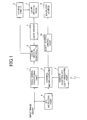
- Fig. 1 is a block diagram of a configuration example of a video displaying apparatus according to one embodiment of the present invention.
- the video displaying apparatus of the embodiment includes a video signal processing part 1 that performs various video processing for an input video signal to generate a form suitable for a display format of display elements of a liquid crystal panel 3, and a liquid crystal controller 2 that outputs a liquid crystal signal to a gate driver 4 and a source driver 5 of the liquid crystal panel 3 based on the display video signal processed by the video signal processing part 1.
- the video displaying apparatus includes an APL detecting part 6 that detects APL (average picture level) of the input video signal for each screen, a remote-controller light-receiving part 7 that receives an instruction signal input by a user using a remote controller (not shown), and a control microcomputer 8 that detects/analyzes the instruction signal received by the remote-controller light-receiving part 7 to control a light-source driving part 10 such as an inverter circuit driving a backlight source 9 based on the APL detected by the APL detecting part 6.
- APL average picture level
- a display panel of the present invention corresponds to the liquid crystal panel 3; a feature quantity detecting part of the present invention corresponds to the APL detecting part 6; and a light-source controlling part corresponds to the control microcomputer 8 and the light-source driving part 10.
- the video displaying apparatus of the embodiment may be either the direct backlight mode or the side-edge backlight mode, and the backlight source 9 may be achieved by using light-emitting diodes (LED), etc., as well as cold cathode fluorescent lamps (CCFL) , which are currently used in general, or may be achieved by using these devices at the same time.
- the luminance controlling method of the backlight source 9 is not limited to the voltage (or current) control and of course the duty (emission pulse width) control may be employed.
- a main characteristic part of the present invention is that the light modulation rate of the backlight source is changed in accordance with changes in the feature quantity of the input video signal based on a difference between times required for the light adaptation and the dark adaptation. Specifically, when the APL is rapidly increased, the light modulation rate of the backlight source 9 is accelerated and the emission luminance of the backlight source 9 is changed in accordance with changes in video such that a viewer does not recognize a change in brightness in the same video. On the other hand, when the APL is rapidly reduced, the light modulation rate of the backlight source 9 is decelerated to change brightness at such a rate that a viewer becomes unrecognizable to changes in brightness due to leak of light. Therefore, mismatch of video and brightness is made less visible to a viewer to improve the video quality.
- the APL detecting unit 6 detects APL of an input video signal and outputs the detection result as an APL signal to the control microcomputer 8.
- the control microcomputer 8 compares the APL signal sent from the APL detecting unit 6 with the previous APL signal to detect a change in the APL.
- the control microcomputer 8 determines a target luminance of the backlight source 9 and determines a change amount of emission luminance (hereinafter, emission luminance change amount) of the backlight source 9 for each predetermined time based on the change in the APL to output the target luminance and the emission luminance change amount to the light-source driving part 10.
- the light-source driving part 10 changes the emission luminance of the backlight source 9 based on the target luminance and the emission luminance change amount sent from the control microcomputer 8.
- Fig. 2 depicts changes of the emission luminance of the backlight source with time in response to changes in APL in the video displaying apparatus shown in Fig. 1 .
- Fig. 2(A) depicts changes of APL and
- Fig. 2(B) depicts changes of the emission luminance of the backlight source with time.
- the control microcomputer 8 determines the emission luminance change amounts such that the emission luminance change amount for the APL of the input video signal changing to a higher level becomes greater than the emission luminance change amount for the APL of the input video signal changing to a lower level. Therefore, as shown in Fig.
- the light modulation rate of the backlight source 9 when the APL is rapidly increased, the light modulation rate of the backlight source 9 can be accelerated to shorten a change time Tr2, and when the APL is rapidly reduced, the light modulation rate of the backlight source 9 can be decelerated to elongate a change time Td2.
- the control microcomputer 8 determines the target luminance of the backlight source 9 depending on the APL of the input video signal, and when the luminance of the backlight source 9 is lower than the determined target luminance, the emission luminance change amount is determined to become greater than a predetermined amount such that the luminance of the backlight source 9 is increased to the target luminance at an accelerated light modulation rate.
- This predetermined amount is, for example, a value preliminarily set for a change from the maximum luminance to the minimum luminance of the backlight source 9 based on a time (rate) required for the light adaptation.
- the light modulation rate can be changed between the cases of increasing and reducing the luminance of the backlight source to perform the light modulation control in accordance with changes in video. That is, as shown in Fig. 2 , when the APL is rapidly increased, the light modulation rate is made faster than a conventional rate to cause the luminance of the backlight source to follow changes in video. Therefore, the light modulation control can be completed before a viewer is light-adapted and the luminance of the backlight source can be increased to the target level without a change in brightness visually recognized by the viewer in the same video.
- Fig. 3 depicts a characteristic curve representing a relationship between APL of the input video signal and the backlight luminance.
- the horizontal axis indicates the APL in percentage (%), and when the entire screen of the displayed video is black, the APL is 0 %, and when the screen is entirely white, the APL is 100 %.
- the vertical axis indicates the emission luminance of the backlight source 9 in percentage (%) , which is 100 % when the backlight luminance is maximized, and the minimum luminance is generally controlled to about 10 % to 20 % at the time of backlight modulation.
- Fig. 3 shows an example of a characteristic curve of backlight using cold cathode fluorescent lamps, and of course a characteristic curve different from Fig. 3 is generated when another light source is used such as LED and organic EL.
- the control microcomputer 8 adaptively changes a drive voltage value (or current value) of the backlight source 9 for the average luminance level of the input video signal by reference to a look-up table using a built-in ROM (not shown) or through calculations using approximate functions. On this occasion, the control microcomputer 8 determines the target luminance of the backlight source 9 based on the APL/backlight luminance (brightness) characteristics shown in Fig. 3 . That is, in the case of the example of the emission luminance control of the backlight source 9 based on Fig. 3 , the emission luminance of the backlight source 9 is controlled to be raised as the APL of the input video signal increases such that the screen luminance is increased.
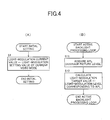
- FIGs. 4 and 5 are explanatory flowcharts of an example of active backlight control of the video displaying apparatus of the present invention. It is assumed that the processing of this example is executed by the video displaying apparatus shown in Fig. 1 , and in Figs.
- a light-modulation current value indicates a set value of the emission luminance currently set in the backlight source 9
- a light-modulation target value indicates a target value of the emission luminance of the backlight source 9
- the number of steps for an up-modulation indicates a change amount of the emission luminance setting value when the light modulation of the backlight source 9 is increased
- the number of steps for a down-modulation indicates a change amount of the emission luminance setting value when the light modulation of the backlight source 9 is reduced.
- the control microcomputer 8 of the video displaying apparatus sets a light-modulation setting value of the current video mode as a light-modulation current value (step S1).
- the video displaying apparatus includes a plurality of video modes and includes different light-modulation setting values for the respective video modes.
- the light-modulation current value is set as a light-modulation setting value depending on a video mode selected by a viewer with a remote controller, etc.
- An example of a light-modulation target value setting processing of the video displaying apparatus of the present invention will be described with reference to Fig. 4 (B) . This processing is executed every 16 msec.
- the control microcomputer 8 of the video displaying apparatus acquires APL (average picture level) of the input video signal (step S11), calculates a light modulation level corresponding to the acquired APL from the characteristic curve (APL/backlight luminance characteristics) shown in Fig. 3 , and sets this level as a light-modulation target value (step S12).
- the control microcomputer 8 of the video displaying apparatus determines whether the light-modulation target value is greater than the light-modulation current value (step S21), and when it is determined that the light-modulation target value is greater than the light-modulation current value (in the case of YES) , it is determined that the APL of the input video signal is changed to a higher level. In this case, the control microcomputer 8 sets the number of steps for the up-modulation as a light-modulation step amount (step S22).
- the control microcomputer 8 adds the light-modulation step amount to the light-modulation current value and determines the result of the addition as the light-modulation current value (step S23).
- the determined light-modulation current value is set in the light-source driving part 10 (step S24).
- the light-source driving part 10 changes the emission luminance of the backlight source 9 based on the light-modulation current value (the target luminance and the emission luminance change amount) sent from the control microcomputer 8.
- step S21 when it is determined at above step S21 that the light-modulation target value is not greater than the light-modulation current value (in the case of NO), the control microcomputer 8 determines whether the light-modulation target value is smaller than the light-modulation current value (step S25). When it is determined that the light-modulation target value is smaller than the light-modulation current value (in the case of YES), it is determined that the APL of the input video signal is changed to a lower level. In this case, the control microcomputer 8 sets the number of steps for the down-modulation as the light-modulation step amount (step S26). This number of steps for down-modulation is set to a value smaller than the number of steps for up-modulation.
- the control microcomputer 8 then subtracts the light-modulation step amount from the light-modulation current value and determines a result of the subtraction as the light-modulation current value (step S27).
- the process goes to step S24 to set to the determined light-modulation current value in the light-source driving part 10.
- the light-source driving part 10 changes the emission luminance of the backlight source 9 based on the light-modulation current value (the target luminance and the emission luminance change amount) sent from the control microcomputer 8.
- step S25 When it is determined at step S25 that the light-modulation target value is not smaller than the light-modulation current value (in the case of NO) , the control microcomputer 8 determines that no change is generated since the light-modulation target value is equal to the light-modulation current value and the processing is directly terminated.
- the number of steps for the up-modulation and the number of steps for the down-modulation correspond to the change amounts of the emission luminance of the backlight source 9 per 32 ms and are assumed to satisfy a relationship of the number of steps for the up-modulation > the number of steps for the down-modulation. Therefore, the light modulation rate at the time of increasing the APL may be faster than the light modulation rate at the time of reducing the APL.
- an average picture level (APL) of a detected area in the display screen is used as the feature quantity of the input video signal in the above mentioned embodiment
- the present invention is not limited to this embodiment and may be configured to obtain and utilize a state (presence or amount) of peak luminance of a video signal of a certain area in the display screen for the luminance modulation of the backlight source.
- the maximum and minimum luminance levels and the luminance distribution status (histogram) in a predetermined area (period) of one frame may be used for the feature quantity of the input video signal, or the backlight source emission luminance may variably be controlled based on a video feature quantity obtained from a combination of two or more thereof.
- the backlight source emission luminance may variably be controlled depending on the feature quantity of the input video signal and the tone correction control of the input video signal may be performed in conjunction with this control.
- a light-modulation rate of a backlight source may be changed in accordance with changes in a feature quantity of an input video signal based on a difference between times required for the light adaptation and the dark adaptation, video quality will not deteriorate in any video and, even if a scene is rapidly made brighter, a viewer does not recognize a change in brightness and does not feel uncomfortable.
Landscapes
- Engineering & Computer Science (AREA)
- Physics & Mathematics (AREA)
- Computer Hardware Design (AREA)
- General Physics & Mathematics (AREA)
- Theoretical Computer Science (AREA)
- Liquid Crystal Display Device Control (AREA)
- Control Of Indicators Other Than Cathode Ray Tubes (AREA)
- Transforming Electric Information Into Light Information (AREA)
- Liquid Crystal (AREA)
Applications Claiming Priority (1)
| Application Number | Priority Date | Filing Date | Title |
|---|---|---|---|
| JP2007253684A JP2009086133A (ja) | 2007-09-28 | 2007-09-28 | 映像表示装置 |
Publications (2)
| Publication Number | Publication Date |
|---|---|
| EP2043079A2 true EP2043079A2 (de) | 2009-04-01 |
| EP2043079A3 EP2043079A3 (de) | 2010-03-17 |
Family
ID=40056181
Family Applications (1)
| Application Number | Title | Priority Date | Filing Date |
|---|---|---|---|
| EP08015642A Withdrawn EP2043079A3 (de) | 2007-09-28 | 2008-09-04 | Videoanzeigegerät mit dynamischer Helligkeitssteuerung des Backlights |
Country Status (4)
| Country | Link |
|---|---|
| EP (1) | EP2043079A3 (de) |
| JP (1) | JP2009086133A (de) |
| CN (1) | CN101399011B (de) |
| BR (1) | BRPI0803562A2 (de) |
Cited By (3)
| Publication number | Priority date | Publication date | Assignee | Title |
|---|---|---|---|---|
| US8588576B2 (en) | 2010-02-26 | 2013-11-19 | Sharp Kabushiki Kaisha | Content reproduction device, television receiver, content reproduction method, content reproduction program, and recording medium |
| RU2642811C2 (ru) * | 2012-06-13 | 2018-01-26 | Сони Корпорейшн | Устройство отображения, способ управления отображением и программа |
| US10162185B2 (en) | 2014-11-04 | 2018-12-25 | Sony Interactive Entertainment Inc. | Head-mounted display and brightness control method |
Families Citing this family (18)
| Publication number | Priority date | Publication date | Assignee | Title |
|---|---|---|---|---|
| JP2011013422A (ja) * | 2009-07-01 | 2011-01-20 | Mitsubishi Electric Corp | 画質調整装置 |
| JP5516583B2 (ja) * | 2009-07-16 | 2014-06-11 | 富士通株式会社 | 表示装置および制御方法 |
| JP5562931B2 (ja) * | 2010-02-26 | 2014-07-30 | シャープ株式会社 | コンテンツ再生装置、テレビジョン受像機、コンテンツ再生方法、コンテンツ再生プログラム、および記録媒体 |
| CN103377636B (zh) * | 2010-05-25 | 2015-06-17 | 友达光电股份有限公司 | 调整背光源的亮度的方法 |
| CN101859546B (zh) * | 2010-05-25 | 2013-06-19 | 友达光电股份有限公司 | 调整背光源的亮度的方法 |
| JP2012013858A (ja) * | 2010-06-30 | 2012-01-19 | Fujitsu Ten Ltd | 表示制御装置、表示装置、及び、表示制御方法 |
| JP5270730B2 (ja) * | 2011-08-03 | 2013-08-21 | シャープ株式会社 | 映像表示装置 |
| CN103843322B (zh) | 2011-10-11 | 2017-10-13 | 索尼公司 | 头戴式显示器及显示控制方法 |
| JP6261240B2 (ja) * | 2013-09-04 | 2018-01-17 | キヤノン株式会社 | 画像処理装置及びその制御方法 |
| US10210816B2 (en) | 2014-09-22 | 2019-02-19 | Nec Display Solutions, Ltd. | Image display apparatus and method for dimming light source |
| JP6479401B2 (ja) * | 2014-10-14 | 2019-03-06 | シャープ株式会社 | 表示装置、表示装置の制御方法、および制御プログラム |
| KR102399669B1 (ko) | 2015-10-15 | 2022-05-19 | 삼성전자주식회사 | 디스플레이 밝기 조정 방법 및 장치 |
| CN105657301B (zh) | 2016-02-22 | 2019-06-11 | 深圳市华星光电技术有限公司 | 显示图像的方法及装置 |
| JP6758891B2 (ja) * | 2016-04-11 | 2020-09-23 | キヤノン株式会社 | 画像表示装置及び画像表示方法 |
| CN106128372A (zh) * | 2016-09-14 | 2016-11-16 | 广州创维平面显示科技有限公司 | 一种直下式背光源的控制方法、控制系统和液晶电视 |
| JP7064889B2 (ja) * | 2018-01-16 | 2022-05-11 | 株式会社ジャパンディスプレイ | 表示装置 |
| JP7114993B2 (ja) * | 2018-03-30 | 2022-08-09 | 株式会社リコー | 表示装置、表示システム、移動体、表示輝度制御方法およびプログラム |
| JP6746855B2 (ja) * | 2018-09-28 | 2020-08-26 | エスゼット ディージェイアイ テクノロジー カンパニー リミテッドSz Dji Technology Co.,Ltd | 撮像装置、制御方法、及びプログラム |
Citations (3)
| Publication number | Priority date | Publication date | Assignee | Title |
|---|---|---|---|---|
| JPH05127608A (ja) | 1991-11-01 | 1993-05-25 | Canon Inc | 液晶表示装置 |
| JP2002357810A (ja) | 2001-05-31 | 2002-12-13 | Matsushita Electric Ind Co Ltd | 映像表示装置及び方法 |
| JP2003036063A (ja) | 2001-04-25 | 2003-02-07 | Matsushita Electric Ind Co Ltd | 映像表示装置及び映像表示方法 |
Family Cites Families (11)
| Publication number | Priority date | Publication date | Assignee | Title |
|---|---|---|---|---|
| JPH0619444A (ja) * | 1992-07-02 | 1994-01-28 | Hitachi Ltd | 情報処理装置 |
| JP2751847B2 (ja) * | 1993-12-28 | 1998-05-18 | 日本電気株式会社 | 表示装置 |
| JP3215400B1 (ja) * | 1999-05-10 | 2001-10-02 | 松下電器産業株式会社 | 画像表示装置および画像表示方法 |
| JP4574057B2 (ja) * | 2000-05-08 | 2010-11-04 | キヤノン株式会社 | 表示装置 |
| CN100358001C (zh) * | 2002-03-07 | 2007-12-26 | 夏普株式会社 | 显示装置 |
| JP2004004532A (ja) * | 2002-03-25 | 2004-01-08 | Sharp Corp | 映像表示装置 |
| JP4250978B2 (ja) * | 2003-03-03 | 2009-04-08 | ヤマハ株式会社 | プロジェクタ |
| WO2005022925A1 (en) * | 2003-08-28 | 2005-03-10 | Koninklijke Philips Electronics N.V. | Method and system for controlling dynamic contrast for in a display system |
| JP4619160B2 (ja) * | 2005-03-17 | 2011-01-26 | シャープ株式会社 | 画像表示装置及び画像表示方法 |
| JP2006285064A (ja) * | 2005-04-04 | 2006-10-19 | Matsushita Electric Ind Co Ltd | 画像表示装置 |
| CN1996103A (zh) * | 2006-08-18 | 2007-07-11 | 深圳创维-Rgb电子有限公司 | 一种用于液晶显示器的节能电路 |
-
2007
- 2007-09-28 JP JP2007253684A patent/JP2009086133A/ja active Pending
-
2008
- 2008-09-04 EP EP08015642A patent/EP2043079A3/de not_active Withdrawn
- 2008-09-25 CN CN2008101661203A patent/CN101399011B/zh not_active Expired - Fee Related
- 2008-09-26 BR BRPI0803562 patent/BRPI0803562A2/pt not_active Application Discontinuation
Patent Citations (3)
| Publication number | Priority date | Publication date | Assignee | Title |
|---|---|---|---|---|
| JPH05127608A (ja) | 1991-11-01 | 1993-05-25 | Canon Inc | 液晶表示装置 |
| JP2003036063A (ja) | 2001-04-25 | 2003-02-07 | Matsushita Electric Ind Co Ltd | 映像表示装置及び映像表示方法 |
| JP2002357810A (ja) | 2001-05-31 | 2002-12-13 | Matsushita Electric Ind Co Ltd | 映像表示装置及び方法 |
Cited By (3)
| Publication number | Priority date | Publication date | Assignee | Title |
|---|---|---|---|---|
| US8588576B2 (en) | 2010-02-26 | 2013-11-19 | Sharp Kabushiki Kaisha | Content reproduction device, television receiver, content reproduction method, content reproduction program, and recording medium |
| RU2642811C2 (ru) * | 2012-06-13 | 2018-01-26 | Сони Корпорейшн | Устройство отображения, способ управления отображением и программа |
| US10162185B2 (en) | 2014-11-04 | 2018-12-25 | Sony Interactive Entertainment Inc. | Head-mounted display and brightness control method |
Also Published As
| Publication number | Publication date |
|---|---|
| CN101399011A (zh) | 2009-04-01 |
| CN101399011B (zh) | 2011-06-15 |
| EP2043079A3 (de) | 2010-03-17 |
| BRPI0803562A2 (pt) | 2009-06-02 |
| JP2009086133A (ja) | 2009-04-23 |
Similar Documents
| Publication | Publication Date | Title |
|---|---|---|
| EP2043079A2 (de) | Videoanzeigegerät mit dynamischer Helligkeitssteuerung des Backlights | |
| US8384654B2 (en) | Liquid crystal display apparatus | |
| EP1983505B1 (de) | Flüssigkristallanzeigeeinrichtung | |
| JP5270730B2 (ja) | 映像表示装置 | |
| US20090085862A1 (en) | Video displaying apparatus | |
| JP5319772B2 (ja) | 液晶表示装置および光源制御方法 | |
| US20100225574A1 (en) | Image display device and image display method | |
| KR20080082011A (ko) | 액정 표시 장치 | |
| US20100309213A1 (en) | Adaptive Stepping-Control System and Method for Dynamic Backlight Control | |
| JP6050601B2 (ja) | 液晶表示装置 | |
| JP2010134438A (ja) | 表示装置および表示装置のイメージ輝度調整方法 | |
| WO2011001726A1 (ja) | 液晶表示装置および光源制御方法 | |
| JP4768232B2 (ja) | 画像表示装置 | |
| JP5326016B2 (ja) | 液晶表示装置 | |
| JP5139623B2 (ja) | 画像表示装置 | |
| WO2010073792A1 (ja) | 液晶表示装置及びテレビ受信装置 | |
| JP4788005B2 (ja) | 輝度調整装置、表示装置、プログラム、輝度調整方法 | |
| JP2008299191A (ja) | 画像表示装置 | |
| JP2018200346A (ja) | 表示装置およびその制御方法 | |
| JP4987134B1 (ja) | 映像表示装置 | |
| De Greef et al. | Adaptive scanning, 1‐D dimming, and boosting backlight for LCD‐TV systems | |
| JP2012194559A (ja) | 映像表示装置 | |
| WO2013187289A1 (ja) | 映像表示装置 |
Legal Events
| Date | Code | Title | Description |
|---|---|---|---|
| PUAI | Public reference made under article 153(3) epc to a published international application that has entered the european phase |
Free format text: ORIGINAL CODE: 0009012 |
|
| AK | Designated contracting states |
Kind code of ref document: A2 Designated state(s): AT BE BG CH CY CZ DE DK EE ES FI FR GB GR HR HU IE IS IT LI LT LU LV MC MT NL NO PL PT RO SE SI SK TR |
|
| AX | Request for extension of the european patent |
Extension state: AL BA MK RS |
|
| PUAL | Search report despatched |
Free format text: ORIGINAL CODE: 0009013 |
|
| AK | Designated contracting states |
Kind code of ref document: A3 Designated state(s): AT BE BG CH CY CZ DE DK EE ES FI FR GB GR HR HU IE IS IT LI LT LU LV MC MT NL NO PL PT RO SE SI SK TR |
|
| AX | Request for extension of the european patent |
Extension state: AL BA MK RS |
|
| 17P | Request for examination filed |
Effective date: 20100914 |
|
| AKX | Designation fees paid |
Designated state(s): DE GB |
|
| 17Q | First examination report despatched |
Effective date: 20120504 |
|
| STAA | Information on the status of an ep patent application or granted ep patent |
Free format text: STATUS: THE APPLICATION IS DEEMED TO BE WITHDRAWN |
|
| 18D | Application deemed to be withdrawn |
Effective date: 20120915 |