EP2043228A2 - Générateur de moteur à espace axial - Google Patents
Générateur de moteur à espace axial Download PDFInfo
- Publication number
- EP2043228A2 EP2043228A2 EP09000607A EP09000607A EP2043228A2 EP 2043228 A2 EP2043228 A2 EP 2043228A2 EP 09000607 A EP09000607 A EP 09000607A EP 09000607 A EP09000607 A EP 09000607A EP 2043228 A2 EP2043228 A2 EP 2043228A2
- Authority
- EP
- European Patent Office
- Prior art keywords
- teeth
- magnet
- stator
- rotor
- removed portion
- Prior art date
- Legal status (The legal status is an assumption and is not a legal conclusion. Google has not performed a legal analysis and makes no representation as to the accuracy of the status listed.)
- Withdrawn
Links
Images





Classifications
-
- H—ELECTRICITY
- H02—GENERATION; CONVERSION OR DISTRIBUTION OF ELECTRIC POWER
- H02K—DYNAMO-ELECTRIC MACHINES
- H02K11/00—Structural association of dynamo-electric machines with electric components or with devices for shielding, monitoring or protection
- H02K11/04—Structural association of dynamo-electric machines with electric components or with devices for shielding, monitoring or protection for rectification
- H02K11/049—Rectifiers associated with stationary parts, e.g. stator cores
- H02K11/05—Rectifiers associated with casings, enclosures or brackets
-
- H—ELECTRICITY
- H02—GENERATION; CONVERSION OR DISTRIBUTION OF ELECTRIC POWER
- H02K—DYNAMO-ELECTRIC MACHINES
- H02K21/00—Synchronous motors having permanent magnets; Synchronous generators having permanent magnets
- H02K21/12—Synchronous motors having permanent magnets; Synchronous generators having permanent magnets with stationary armatures and rotating magnets
- H02K21/24—Synchronous motors having permanent magnets; Synchronous generators having permanent magnets with stationary armatures and rotating magnets with magnets axially facing the armatures, e.g. hub-type cycle dynamos
-
- B—PERFORMING OPERATIONS; TRANSPORTING
- B60—VEHICLES IN GENERAL
- B60L—PROPULSION OF ELECTRICALLY-PROPELLED VEHICLES; SUPPLYING ELECTRIC POWER FOR AUXILIARY EQUIPMENT OF ELECTRICALLY-PROPELLED VEHICLES; ELECTRODYNAMIC BRAKE SYSTEMS FOR VEHICLES IN GENERAL; MAGNETIC SUSPENSION OR LEVITATION FOR VEHICLES; MONITORING OPERATING VARIABLES OF ELECTRICALLY-PROPELLED VEHICLES; ELECTRIC SAFETY DEVICES FOR ELECTRICALLY-PROPELLED VEHICLES
- B60L50/00—Electric propulsion with power supplied within the vehicle
- B60L50/50—Electric propulsion with power supplied within the vehicle using propulsion power supplied by batteries or fuel cells
- B60L50/60—Electric propulsion with power supplied within the vehicle using propulsion power supplied by batteries or fuel cells using power supplied by batteries
- B60L50/66—Arrangements of batteries
-
- H—ELECTRICITY
- H02—GENERATION; CONVERSION OR DISTRIBUTION OF ELECTRIC POWER
- H02K—DYNAMO-ELECTRIC MACHINES
- H02K1/00—Details of the magnetic circuit
- H02K1/06—Details of the magnetic circuit characterised by the shape, form or construction
- H02K1/12—Stationary parts of the magnetic circuit
- H02K1/14—Stator cores with salient poles
- H02K1/146—Stator cores with salient poles consisting of a generally annular yoke with salient poles
- H02K1/148—Sectional cores
-
- H—ELECTRICITY
- H02—GENERATION; CONVERSION OR DISTRIBUTION OF ELECTRIC POWER
- H02K—DYNAMO-ELECTRIC MACHINES
- H02K3/00—Details of windings
- H02K3/46—Fastening of windings on the stator or rotor structure
- H02K3/52—Fastening salient pole windings or connections thereto
- H02K3/521—Fastening salient pole windings or connections thereto applicable to stators only
- H02K3/522—Fastening salient pole windings or connections thereto applicable to stators only for generally annular cores with salient poles
-
- B—PERFORMING OPERATIONS; TRANSPORTING
- B60—VEHICLES IN GENERAL
- B60L—PROPULSION OF ELECTRICALLY-PROPELLED VEHICLES; SUPPLYING ELECTRIC POWER FOR AUXILIARY EQUIPMENT OF ELECTRICALLY-PROPELLED VEHICLES; ELECTRODYNAMIC BRAKE SYSTEMS FOR VEHICLES IN GENERAL; MAGNETIC SUSPENSION OR LEVITATION FOR VEHICLES; MONITORING OPERATING VARIABLES OF ELECTRICALLY-PROPELLED VEHICLES; ELECTRIC SAFETY DEVICES FOR ELECTRICALLY-PROPELLED VEHICLES
- B60L2200/00—Type of vehicles
- B60L2200/12—Bikes
-
- B—PERFORMING OPERATIONS; TRANSPORTING
- B60—VEHICLES IN GENERAL
- B60L—PROPULSION OF ELECTRICALLY-PROPELLED VEHICLES; SUPPLYING ELECTRIC POWER FOR AUXILIARY EQUIPMENT OF ELECTRICALLY-PROPELLED VEHICLES; ELECTRODYNAMIC BRAKE SYSTEMS FOR VEHICLES IN GENERAL; MAGNETIC SUSPENSION OR LEVITATION FOR VEHICLES; MONITORING OPERATING VARIABLES OF ELECTRICALLY-PROPELLED VEHICLES; ELECTRIC SAFETY DEVICES FOR ELECTRICALLY-PROPELLED VEHICLES
- B60L2220/00—Electrical machine types; Structures or applications thereof
- B60L2220/10—Electrical machine types
- B60L2220/12—Induction machines
-
- B—PERFORMING OPERATIONS; TRANSPORTING
- B60—VEHICLES IN GENERAL
- B60L—PROPULSION OF ELECTRICALLY-PROPELLED VEHICLES; SUPPLYING ELECTRIC POWER FOR AUXILIARY EQUIPMENT OF ELECTRICALLY-PROPELLED VEHICLES; ELECTRODYNAMIC BRAKE SYSTEMS FOR VEHICLES IN GENERAL; MAGNETIC SUSPENSION OR LEVITATION FOR VEHICLES; MONITORING OPERATING VARIABLES OF ELECTRICALLY-PROPELLED VEHICLES; ELECTRIC SAFETY DEVICES FOR ELECTRICALLY-PROPELLED VEHICLES
- B60L2240/00—Control parameters of input or output; Target parameters
- B60L2240/40—Drive Train control parameters
- B60L2240/42—Drive Train control parameters related to electric machines
- B60L2240/423—Torque
-
- B—PERFORMING OPERATIONS; TRANSPORTING
- B60—VEHICLES IN GENERAL
- B60L—PROPULSION OF ELECTRICALLY-PROPELLED VEHICLES; SUPPLYING ELECTRIC POWER FOR AUXILIARY EQUIPMENT OF ELECTRICALLY-PROPELLED VEHICLES; ELECTRODYNAMIC BRAKE SYSTEMS FOR VEHICLES IN GENERAL; MAGNETIC SUSPENSION OR LEVITATION FOR VEHICLES; MONITORING OPERATING VARIABLES OF ELECTRICALLY-PROPELLED VEHICLES; ELECTRIC SAFETY DEVICES FOR ELECTRICALLY-PROPELLED VEHICLES
- B60L2270/00—Problem solutions or means not otherwise provided for
- B60L2270/10—Emission reduction
- B60L2270/14—Emission reduction of noise
- B60L2270/142—Emission reduction of noise acoustic
-
- B—PERFORMING OPERATIONS; TRANSPORTING
- B60—VEHICLES IN GENERAL
- B60L—PROPULSION OF ELECTRICALLY-PROPELLED VEHICLES; SUPPLYING ELECTRIC POWER FOR AUXILIARY EQUIPMENT OF ELECTRICALLY-PROPELLED VEHICLES; ELECTRODYNAMIC BRAKE SYSTEMS FOR VEHICLES IN GENERAL; MAGNETIC SUSPENSION OR LEVITATION FOR VEHICLES; MONITORING OPERATING VARIABLES OF ELECTRICALLY-PROPELLED VEHICLES; ELECTRIC SAFETY DEVICES FOR ELECTRICALLY-PROPELLED VEHICLES
- B60L2270/00—Problem solutions or means not otherwise provided for
- B60L2270/10—Emission reduction
- B60L2270/14—Emission reduction of noise
- B60L2270/145—Structure borne vibrations
-
- H—ELECTRICITY
- H02—GENERATION; CONVERSION OR DISTRIBUTION OF ELECTRIC POWER
- H02K—DYNAMO-ELECTRIC MACHINES
- H02K1/00—Details of the magnetic circuit
- H02K1/06—Details of the magnetic circuit characterised by the shape, form or construction
- H02K1/12—Stationary parts of the magnetic circuit
- H02K1/18—Means for mounting or fastening magnetic stationary parts on to, or to, the stator structures
- H02K1/185—Means for mounting or fastening magnetic stationary parts on to, or to, the stator structures to outer stators
-
- Y—GENERAL TAGGING OF NEW TECHNOLOGICAL DEVELOPMENTS; GENERAL TAGGING OF CROSS-SECTIONAL TECHNOLOGIES SPANNING OVER SEVERAL SECTIONS OF THE IPC; TECHNICAL SUBJECTS COVERED BY FORMER USPC CROSS-REFERENCE ART COLLECTIONS [XRACs] AND DIGESTS
- Y02—TECHNOLOGIES OR APPLICATIONS FOR MITIGATION OR ADAPTATION AGAINST CLIMATE CHANGE
- Y02T—CLIMATE CHANGE MITIGATION TECHNOLOGIES RELATED TO TRANSPORTATION
- Y02T10/00—Road transport of goods or passengers
- Y02T10/60—Other road transportation technologies with climate change mitigation effect
- Y02T10/64—Electric machine technologies in electromobility
-
- Y—GENERAL TAGGING OF NEW TECHNOLOGICAL DEVELOPMENTS; GENERAL TAGGING OF CROSS-SECTIONAL TECHNOLOGIES SPANNING OVER SEVERAL SECTIONS OF THE IPC; TECHNICAL SUBJECTS COVERED BY FORMER USPC CROSS-REFERENCE ART COLLECTIONS [XRACs] AND DIGESTS
- Y02—TECHNOLOGIES OR APPLICATIONS FOR MITIGATION OR ADAPTATION AGAINST CLIMATE CHANGE
- Y02T—CLIMATE CHANGE MITIGATION TECHNOLOGIES RELATED TO TRANSPORTATION
- Y02T10/00—Road transport of goods or passengers
- Y02T10/60—Other road transportation technologies with climate change mitigation effect
- Y02T10/70—Energy storage systems for electromobility, e.g. batteries
Definitions
- the invention relates to an axial gap dynamo-electric machine comprising a rotor having a revolving shaft supported by a bearing and a magnet for generating a magnetic field, a stator yoke disposed so as to oppose the rotor, and a plurality of teeth being disposed on the magnet-opposed surface of the stator yoke substantially in the shape of a partly removed circle, wherein a removed portion is free of teeth, the partially removed circle having a midpoint at a predetermined point in relation to a center axis of the bearing and opposing the magnet at a predetermined gap.
- the invention relate to an apparatus, in particular, a driving machine, such as a motorcycle.
- Such inclination of the rotor increases noise/vibrations generated by the rotational movement of the dynamo-electric machine, and also increases loss at the gear portion connected to the bearing or the revolving shaft of the rotor, whereby practicability of the axial gap dynamo-electric machine (for example, mountability to electric vehicles/electric motorcycles) may be impaired.
- circumferential pitches among the plurality of teeth are set to increase from a third tooth being positioned further away from the removed portion, in particular, on the opposite side of the center axis relative to the midpoint between a first and a second tooth being located on both sides of and closest to the removed portion, in particular, at a position closest to a second plane including the midpoint and the center axis toward the first and the second teeth in sequence.
- areas of the magnet-opposed surfaces of the plurality of teeth are set to increase from a third tooth positioned further away from the removed portion, in particular, on the opposite side of the center axis of the bearing relative to a midpoint between first and second teeth positioned closest to and on both sides of the removed portion, in particular, at a position closest to a second plane including the midpoint and the center axis toward the first and second teeth in sequence.
- the above object is solved in an inventive manner by comprising an axial gap dynamo-electric machine according to at least one of the claims 1 to 19.
- the controller 37 and an inverter 70 connected to the controller 37 and electrically connected to the respective coils 62 for switching and allowing a current to flow through the coils 62 (U-phase coil, V-phase coil, and W-phase coil) under control of the controller 37 are disposed on the stator yoke 60 and a portion on which the teeth 61 are missing (removed portion) TW.
- Reference numeral 71 designates an encoder substrate for detecting the rotational position of the rotor 40, and reference numerals 71a, 71b, 71c designate holes IC corresponding to the respective phases.
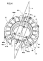
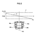
- the stator yoke 60 is inclined in such a manner that the first and the second teeth 61a1 and 61a2 are closer to surface of the magnet 45 opposing the stator than the third tooth 61a3, so that the plane including the first and the second points P1 and P2 and the third point P3 is inclined with respect to the perpendicular direction X.
- two flanges 64a1, 64a2 positioned on the upper side in a state in which the stator 41 is mounted to the rear end section 20a of the rear arm 20 are disposed substantially symmetrically with respect to a line L passing an uppermost point M1 and a lowermost point M2 in a state in which the stator 41 is mounted.
- the teeth 61 to be energized may be shifted sequentially so that the rotor 40 is rotated with the magnet 45.
- the stator yoke 60 is formed substantially into a ring shape for securing a space of the bearings 38a, 38b of the rotor 40, and part of the ring shape is removed to form the shape of a partly removed circle (ring), so that the controller 37 or the like may be disposed to the removed portion TW to realize downsizing.
- the connecting yoke 75 when the connecting yoke 75 is not provided, the magnetic circuit between the teeth 61a1 and 61a2 in the vicinity of the both side of the removed portion TW is disconnected, and thus the magnetic flux passing through the teeth 61a1 and 61a2 is weakened, which may cause lowering of torque.
- Fig. 6 is a comparative drawing comparing a loss L01 resulted from employment of an electric motor having a construction in which the first and the second points P1 and p2 on the magnet-opposed surfaces of the first and the second teeth 61a1 and 61a2 and the third point P3 on the magnet-opposed surface of the third tooth 61 a3 are in the same plane (not inclined) with a loss LO2 resulted from employment of the electric motor 28 having a construction according to the first embodiment of the present invention (the construction in which the plane including the first and the second points P1 and P2 on the magnet-opposed surfaces of the first and the second teeth 61a1 and 61a2 and the third point P3 on the magnet-opposed surface of the third tooth 61 a3 is inclined in such a manner that the first and the second points P1 and P2 are positioned at a level, for example, about 0.2 mm higher than the third point P3) (vertical axis represents the loss (%)).
- the loss LO2 resulted from the case where the electric motor 28 according to the first embodiment of the present invention is used is about 10% less than the loss L01 resulted from the case where the electric motor without inclination is used, whereby the effect of the construction (inclined construction) of the present embodiment is proved.
- the two flanges 64a1, 64a2 positioned on the upper side are disposed so as to be substantially symmetrical with respect to the line L passing the uppermost point M1 and the lowermost point M2 in the stator 41 mounted state.
- the impact load may be dispersed to the two flanges 64a1, 64a2.
- Fig. 7 is a perspective view showing a general construction of a stator 41A of the electric motor according to a second embodiment of the present invention.
- the construction of the stator 41 is different from the first embodiment. Therefore, description of other components will not be described or will be made only briefly.
- the stator yoke 60 is not inclined, and the heights of the plurality of the respective teeth 61 are formed so as to increase from the third tooth 61a3 toward the first and the second teeth 61a1 and 61a2 step-by-step in order to incline a plane S1 including the first and the second points P1 and P2 on the magnet-opposed surfaces of the first and the second teeth 61a1 and 61a2 and the third point P3 on the magnet-opposed surface of the third tooth 61a3 in such a manner that the first and the second points P1 and P2 are higher than the third point P3.
- the heights of the plurality of teeth from the third tooth 61a3 to the first tooth 61a1, that is, 61a3, 61ak1, 61ak2, ..., 61ak6, 61a1, are such that the height of the third tooth 61 a3 is the lowest and, from the next on, the height of the teeth increases toward the first tooth 61a1, so that the height of the first tooth 61a1 is the highest (the height of the third tooth 61a3 ⁇ the height of the tooth 61ak1 ⁇ ... ⁇ the height of the first tooth 61 ak6 ⁇ the height of the first tooth 61a1).
- the heights of the plurality of teeth from the third tooth 61 a3 to the second tooth 61a2, that is, 61a3, 61am1, 61am2,..., 61am6, 61a1 are such that the height of the third tooth 61 a3 is the lowest, and from the next on, the height of the teeth increases toward the second tooth 61a2, so that the height of the second tooth 61a2 is the highest (the height of the third tooth 61a3 ⁇ the height of the tooth 61am1 ⁇ ... ⁇ the height of the tooth 61am6 ⁇ the height of the second tooth 61a2).
- the plane H including the first and the second points P1 and P2 on the magnet opposing the fist and the second teeth 61a1 and 61a2 and the third point P3 on the magnet-opposed surface of the third tooth 61a3 may be inclined in such a manner that the first and the second points P1 and P2 are higher than the third point P3, and thus unbalance (disequilibrium) of the attractive force of the magnet 45 on the rotor with respect to the stator 41 may be alleviated as in the first embodiment.
- the circumferential pitches of the plurality of teeth 61 determined by angles between the adjacent line segments V1-V8 are determined so as to increase in sequence from the third tooth 61a3 toward the first and the second teeth 61a1 and 61a2.
- the respective circumferential pitches ⁇ 1, ⁇ 2,..., ⁇ 7 of the plurality of teeth from the third tooth 61a3 to the second tooth 61a2, that is, 61a3, 61am1, ..., 61am6, 61a2, are such that the circumferential pitch ⁇ 1 between the third tooth 61 a3 and the adjacent tooth 61am1 is the smallest, and from the next on, the circumferential pitch increases toward the second tooth 61a2, so that the circumferential pitch ⁇ 7 between the teeth 61am6 and the second tooth 61a2 is the largest (circumferential pitch ⁇ 1 ⁇ circumferential pitch ⁇ 2 ⁇ ... ⁇ circumferential pitch ⁇ 6 ⁇ circumferential pitch ⁇ 7).
- the signs ⁇ t in the drawing represent regular circumferential pitches in the case in which the plurality of teeth from the third tooth 61 a3 to the second tooth 61a2, that is, 61a3, 61am1, ..., 61 am6, 61 a2 are disposed at regular circumferential pitches.
- the plurality of teeth 61 can be positioned closer to the removed portion TW than the case in which the plurality of teeth 61 are disposed at regular circumferential pitches ⁇ t.
- the teeth may be shifted toward the removed portion TW by increasing the circumferential pitches of the teeth 61a1, 61ak1-61ak6, 61 a2, 61am1-61am2 other than the third tooth 61 a3.
- overall distribution of the plurality of teeth 61 that is, distribution of the steel plate (iron) on the stator yoke 60 may be increased on the side of the removed portion TW and decreased on the opposed teeth 61 a3 side.
- the attractive force of the magnet 45 with respect to the removed portion TW may be increased and in contrast, the attractive force of the magnet 45 with respect to the tooth 61a3 may be decreased corresponding to the increased amount of the steel plate (iron) on the stator yoke 60. Therefore, unbalance (disequilibrium) of the attractive force of the magnet 45 with respect to the side of the removed portion TW and the opposite side (tooth 61 a3 and so on) of the center axis BO may be alleviated, and inclination of the rotor 40 caused by unbalance of the attractive force may be restrained, so that vibrations/noise, or loss may be reduced.
- the circumferential pitches among the plurality of teeth 61 are determined to be uneven so as to increase from the third tooth 61 a3 toward the first and the second teeth 61a1 and 61a2 in sequence.
- the present invention is not limited thereto, and any uneven pitches may be applicable as long as overall distribution of the plurality of teeth 61 can be increased on the side of the removed portion TW, and decreased on the opposed tooth 61 a3 side, so that the attractive force of the magnet 45 with respect to the side of the removed portion TW can be increased.
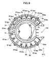
- Fig. 9 is a plan view showing a general construction of a stator 41C of the electric motor according to the fourth embodiment of the present invention when viewed from the rear wheel side.
- a stator 41C of the electric motor according to the fourth embodiment of the present invention when viewed from the rear wheel side.
- description of other components will not be described or will be made only briefly.
- stator 41C of the present embodiment as a method of changing distribution of the steel plate (iron) on the stator yoke 60, unbalance (disequilibrium) of the attractive force of the magnet 45 with respect to the teeth 61 is alleviated by making the area of the magnet-opposed surfaces of the plurality of teeth 61 uneven.
- the areas S1, S2,..., S8 of the magnet-opposed surfaces of the plurality of teeth from the third tooth 61a3 to the second tooth 61a2, that is, teeth 61a3, 61am1, ..., 61am6, 61a2, respectively, are increased in sequence from the third tooth 61 a3 toward the first and the second teeth 61a1 and 61 a2.
- the widths W1, W2,..., W8 along the shorter sides of the magnet-opposed surfaces of the plurality of teeth from the third tooth 61a3 to the second tooth 61a2, that is, 61a3, 61am1, ..., 61am6, 61a2, are increased in sequence from the third tooth 61a3 toward the first and the second teeth 61a1 and 61a2.
- the areas S1, S2,..., S8 of the magnet-opposed surfaces (the widths W1, W2,..., W8 of the magnet-opposed surfaces) of the plurality of teeth from the third tooth 61 a3 to the second tooth 61a2, that is, teeth 61a3, 61am1, ..., 61am6, 61a2, respectively, are the smallest (shortest) at the third tooth 61 a3, and from the next on, are increasing in sequence toward the second tooth 61a2, and the area S8 of the magnet-opposed surface of the second teeth 61a2 (the width of the magnet-opposed surface W8) is the largest (longest)(area of magnet-opposed surface S1 (width W1 of magnet-opposed surface) ⁇ area S2 of magnet-opposed surface (width W2 of magnet-opposed surface) ⁇ .. ⁇ area S7 of magnet-opposed surface (width W7 of magnet-opposed surface) ⁇ area S8 of magnet-opposed surface
- the areas of the magnet-opposed surfaces (the width of the magnet-opposed surfaces) of the plurality of teeth from the third tooth 61 a3 to the first tooth 61a1, that is, 61a3, 61ak1,..., 61ak6, 61a1, are the same as in the case of the plurality of teeth 61a3-61a2, and the area of the magnet-opposed surface (the width of the magnet-opposed surface) is the smallest (shortest) at the third teeth 61 a3, and from the next on, increases toward the first tooth 61a1 in sequence, so that the area of the magnet-opposed surface (width of the magnet-opposed surface) of the first tooth 61a1 is the largest (longest).
- distribution of iron on the stator yoke 60 may be deflected from the third tooth 61 a3 toward the removed portion TW according to the change of the magnet-opposed surface thereof.
- overall distribution of the plurality of teeth 61 that is, distribution of the steel plates (iron) on the stator yoke 60 may be increased on the side of the removed portion TW and decreased on the opposed tooth 61 a3 side.
- the attractive force of the magnet 45 with respect to the side of the removed portion TW may be increased by the extent corresponding to the increased amount of the steel plate (iron) on the stator yoke 60, and in contrast, the attractive force of the magnet 45 with respect to the tooth 61a3 may be reduced. Therefore, unbalance (disequilibrium) of the attractive force of the magnet 45 with respect to the opposite side of the center axis BO relative to the side of the removed portion TW (e.g., tooth 61 a3) may be alleviated, and thus inclination of the rotor 40 caused by the unbalanced attractive force may be restrained and thus vibrations/noise or loss may be reduced.
- the widths of the shorter sides of the magnet-opposed surface of the plurality of teeth from the third tooth 61a3 to the first and the second teeth 61a1 and 61 a2 are increased in sequence.
- the present invention is not limited to, and what is required is only that the areas of the magnet-opposed surfaces from the third tooth 61a3 to the first and the second teeth 61a1 and 61 a2 can be increased, and thus increase in longitudinal width of the magnet-opposed surfaces or deformation of the magnet-opposed surfaces may also be applicable.
- the areas of the respective magnet-opposed surfaces of the plurality of teeth 61 are uneven such that it increases from the third tooth 61a3 to the first and the second teeth 61a1 and 61a2 in sequence.
- the present invention is not limited thereto, and any uneven areas are included as long as overall distribution of the plurality of teeth 61 may be increased to the side of the removed portion TW, and decreased on the opposed tooth 61 a3 side, so that the attractive force of the magnet 45 with respect to the side of the removed portion TW is increased.
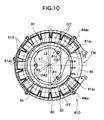
- Fig. 10 is a plan view showing a general construction of a stator 41 D of the electric motor according to the fifth embodiment of the present invention when viewed from the rear wheel side.
- a stator 41 D of the electric motor according to the fifth embodiment of the present invention when viewed from the rear wheel side.
- description of other components will not be described or will be made only briefly.
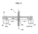
- reference sign OA1 designates a center of the plurality of teeth 61 disposed in the shape of a partly removed circle (the center of a circle formed by connecting the centers OT of the respective magnet-opposed surfaces of the plurality of teeth 61), and reference sign OA2 represents the center (the center axis BO of the bearings 38a, 38b) of the revolving shaft 42e of the rotor 40, which corresponds to the center of the ring-shaped magnet 45.
- a first length L1 along the radial direction between respective surfaces 61 c on the inner peripheral sides of the respective teeth 61 and the center OA1 of the partly removed circle and the length of the inner radius R1 of the ring-shaped magnet 45 are substantially aligned
- a second length L2 along the radial direction between surfaces 61d on the outer peripheral surfaces of the respective teeth 61 and the center OA1 of the partly removed circle and the length of the outer radius R2 of the ring-shaped magnet 45 are substantially aligned.
- the center OA1 of the plurality of teeth 61 disposed in the partly removed circle and the center OA2 of the revolving shaft 42e of the rotor 40 are deviated along the radial direction so that the removed portion TW is shifted away from the center OA2 of the revolving shaft 42e of the rotor 40.
- the length LX1 from the centerline passing through the center OA2 of the revolving shaft of the rotor 40 (identical to the center axis BO of the bearings 38a, 38b) to a predetermined position (for example, the center OT) of the teeth on the side of the removed portion TW may be set to a length longer than the length LX2 to a corresponding predetermined position (the center OT) of the teeth (for example, tooth 61a3) on the opposite side of the center axis BO relative to the removed portion TW.
- moment along the center axis BO exerted to the teeth (e.g., teeth 61a1, 61a2) on the side of the removed portion TW with respect to the center OA2 of the revolving shaft of the rotor 40 that is, moment based on the attractive force of the magnet 45 ⁇ obtained from a product of a force exerted to the teeth (magnetic force; attractive force) and a length to the teeth ⁇ is such that moment on the tooth 61a3 side which is opposite from the side of the removed portion TW is larger and thus the rotor 40 is inclined toward the tooth 61 a3 side since the attractive force of the magnet 45 is not even in case of normal arrangement (when the center OA2 of the revolving shaft of the rotor 40 coincides with the center OA1 of the pertly-removed circle).
- the length LX1 from the center axis BO passing through the center OA2 of the revolving shaft of the rotor 40 to the teeth on the side of the removed portion TW may be set to a length longer than the length LX2 to the teeth on the opposite side of the center axis BO relative to the removed portion TW, lack of magnetic force caused by missing of teeth on the side of the removed portion TW may be compensated by the aforementioned increase in length to the teeth on the side of the removed portion TW.
- moment generated by the attractive force of a magnet 45A with respect to the plurality of teeth on the side of the removed portion TW about the center OA2 of revolving shaft of the rotor 40 (center axis BO) and moment generated by the plurality of teeth on the opposite side of the center axis BO relative to the removed portion TW may be balanced.
- inclination of the rotor 40 toward the opposite side of the center axis BO relative to the removed portion TW is alleviated and thus vibrations/noise or lost may be removed.
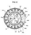
- Fig. 12 is a plan view of a general construction of a stator 41 E of the electric motor according to the sixth embodiment of the present invention when viewed from the rear wheel side.
- the construction of the rotor described in conjunction with the fifth embodiment is different.
- the length of the inner radius R1 of the ring-shaped magnet 45A is shorter than the first length L1 along the radial direction between the inner peripheral surfaces 61 c of the respective teeth 61 and the center OA1 of the partly removed circle, and the length of the outer radius R2 of the ring-shaped magnet 45 is longer than the second length L2 along the radial direction between the outer peripheral surfaces 61 d of the respective teeth 61 and the center OA1 of the partly removed circle.
- the center OA1 of the plurality of teeth 61 disposed into the shape of a partly removed circle and the center OA2 of the revolving shaft 42e of the rotor 40 are deviated along the direction of diameter so that the removed portion TW is shifted away from the center OA2 of the revolving shaft 42e of the rotor 40.
- the length LX1 from the centerline passing through the center OA2 of the revolving shaft of the rotor 40 (the center axis BO) to a predetermined position (for example, the center OT) of the teeth on the side of the removed portion TW may be set to a length longer than the length LX2 to a corresponding predetermined position (the center OT) of the teeth (for example, tooth 61 a3) on the opposite side of the center axis BO relative to the removed portion TW.
- the length LX1 from the center axis BO passing through the center OA2 of the revolving shaft of the rotor 40 to the teeth on the side of the removed portion TW may be set to a length longer than the length LX2 to the teeth on the opposite side of the center axis BO relative to the removed portion TW, lack of magnetic force caused by missing of teeth on the side of the removed portion TW may be compensated by the aforementioned increase in length to the teeth on the side of the removed portion TW.
- moment generated by the attractive force of the magnet 45A with respect to the plurality of teeth on the side of the removed portion TW about the center OA2 of the revolving shaft of the rotor 40 (center axis BO) and moment generated by the plurality of teeth on the opposite side of the center axis BO relative to the removed portion TW may be balanced.
- inclination of the rotor 40 toward the opposite side of the center axis BO relative to the removed portion TW is alleviated and thus vibrations/noise or lost may be removed.
- the length of the inner radius R1 of the ring-shaped magnet 45A is shorter than the first length L1 along the radial direction between the inner peripheral surfaces 61 c of the respective teeth and the center OA1 of the partly removed circle, and the length of the outer radius R2 of the ring-shaped magnet 45A is longer than the second length L2 along the radial direction between the outer peripheral surfaces 61d of the respective teeth and the center OA1 of the partly removed circle, as shown in Fig.
- the magnet-opposed surface of all the teeth 61 can be faced to the magnet 45A completely (all the teeth 61 can be positioned in the ring-shaped region of the magnet 45A), so that inclination of the rotor 40 may be restrained without lowering the amount of magnetic flux (lowering torque).
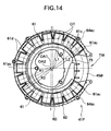
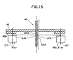
- Fig. 14 is a plan view showing a general construction of a stator 41 F of the electric motor according to the seventh embodiment of the present invention when viewed from the rear wheel side.
- the construction of the rotor described in conjunction with the fifth embodiment or with the sixth embodiment is different.
- the length of the inner radius R1 of a ring-shaped magnet 45B and the first length L1 along the radial direction between the surfaces 61 c on the inner peripheral side of the respective teeth 61 and the center OA1 of the partly removed circle are substantially aligned, and the length of the outer radius R2 of the ring-shaped magnet 45B is set to the length longer than the second length L2 along the radial direction between the outer peripheral surfaces 61 d of the respective teeth 61 and the center OA1 of the partly removed circle.
- the center OA1 of the plurality of teeth 61 arranged in the shape of a partly removed circle and the center OA2 (center of the ring-shaped magnet 45B) of the revolving shaft 42e of the rotor 40 are deviated along the direction of diameter so that the removed portion TW is shifted away from the center OA2 of the revolving shaft 42e of the rotor 40.
- the length LX1 from the centerline passing through the center OA2 of the rotational shaft of the rotor 40 (the center axis BO) to a predetermined position (for example, the center OT) of the teeth on the side of the removed portion TW may be set to a length longer than the length LX2 to a corresponding predetermined position (the center OT) of the teeth (for example, tooth 61a3) on the opposite side of the center axis BO relative to the removed portion TW.
- the length LX1 from the center axis BO passing through the center OA2 of the revolving shaft of the rotor 40 to the teeth on the side of the removed portion TW may be set to a length longer than the length LX2 to the teeth on the opposite side of the center axis BO relative to the removed portion TW, lack of magnetic force caused by missing of teeth on the side of the removed portion TW may be compensated by the aforementioned increase in length to the teeth on the side of the removed portion TW.
- moment generated by the attractive force of the magnet 45B with respect to the plurality of teeth on the side of the removed portion TW about the center OA2 of revolving shaft of the rotor 40 (center axis BO) and moment generated by the plurality of teeth on the opposite side of the center axis BO relative to the removed portion TW may be balanced.
- inclination of the rotor 40 toward the opposite side of the center axis BO relative to the removed portion TW is alleviated and thus vibrations/noise or lost may be removed.
- the length LX1 may be set to a length longer than the length LX2, the magnet-opposed surfaces of the teeth (for example, the teeth 61a1, 61a2) on the side of the removed portion TW may be opposed to the magnet 45B substantially completely, and the areas of the magnet 45B opposed surfaces of a teeth (for example, the teeth 61 a3) on the opposite side of the center axis BO relative to the removed portion TW may be reduced.
- the fifth to the seventh embodiments simply show examples of the relations between the first and the second lengths L1 and L2 along the radial direction between the inner peripheral surfaces 61 c and the outer peripheral surfaces 61 d of the respective teeth 61 and the center OA1 of the partly removed circle, and the inner radius R1 and the outer radius R2 of the ring-shaped magnet 45 (45A, 45B) are shown.
- the magnitude relation between the inner radius and the outer radius of the magnet 45 (45A, 45B), and the first and the second lengths L1 and L2 between the inner peripheral surfaces 61 c and the outer peripheral surfaces 61d of the respective teeth 61 and the center OA1 of the partly removed circle may be determined as appropriate as far as the construction is such that the center OA1 of the plurality of teeth 61 and the center OA2 of the revolving shaft 42e of the rotor 40 are deviated so that moment on the side of the removed portion TW and moment on the opposite side of the center axis BO relative to the removed portion TW may be balanced.
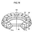
- a stator 83 provided with a plurality of teeth 81 disposed on the magnet 45 opposed surface of a stator yoke 80 formed substantially in the shape of a partly removed circle according to the first to the seventh embodiments, as shown in Fig. 16 , it is also possible to simply connect the opposing inner peripheral portions on both ends 80a1 and 80a2 on the side of the removed portion TW of the stator yoke 80 by a connecting yoke 85.
- the magnetic circle between teeth 81a1 and 81a2 in the vicinity of both sides of the removed portion TW may be maintained by the connecting yoke 85.
- lowering of the attractive force of the teeth on the side of the removed portion may be prevented in comparison with the case in which there is no connecting yoke 85, which contributes to alleviation of unbalance of the attractive force caused by the presence of the removed portion.
- the present invention is not limited thereto, and it may be mounted on other apparatus/equipment, and the effects as described above may be achieved.
- the present invention is not limited thereto, and it is also used as so-called electric generator, which allows a coil to generate electromotive force by rotating the rotor from the outside.
- the invention is not limited to the above-described first to the seventh embodiments, and may be embodied in other modes by modifying as desired within the scope of the claims of the invention.
- the respective embodiments and/or features thereof may be combined amongst each other with one or more of the embodiments.
- a rotor having a revolving shaft supported by a bearing and a magnet for magnetic field are rotated, including a stator yoke disposed so as to oppose the rotor, and a plurality of teeth being disposed on the surface of the stator yoke so as to oppose the magnet in the shape of a partly removed circle having a midpoint thereof at a predetermined point on the center axis of the bearing and opposing the magnet at a predetermined gap, wherein a plane including first and second points on the magnet-opposed surfaces of the first and the second teeth out of the plurality of teeth on both sides of the removed portion and a third point on the magnet-opposed surface of the third tooth positioned on the opposite side of the center axis of the bearing relative to the center point between the first and the second teeth and being closest to a plane including the center point and the center axis is inclined from the direction perpendicular to the center axis of the bearing.
- an axial gap dynamo-electric machine in which a rotor having a revolving shaft and a magnet for magnetic field are rotated including: a stator yoke disposed so as to oppose the rotor; and a plurality of teeth being disposed on the surface of the stator yoke so as to oppose the magnet substantially in the shape of a partly removed circle having a midpoint thereof at a predetermined point on the center axis of the revolving shaft and opposing the magnet at a predetermined gap, wherein circumferential pitches among the plurality of teeth are uneven so that an attractive force of the magnet with respect to the removed portion increases.
- a rotor having a revolving shaft and a magnet for magnetic field are rotated including: a stator yoke disposed so as to oppose the rotor; and a plurality of teeth being disposed on the surface of the stator yoke so as to oppose the magnet substantial in the shape of a partly removed circle having a midpoint thereof on the center axis of the revolving shaft and opposing the magnet at a predetermined gap, wherein an areas of the plurality of teeth opposing to the magnet are uneven so that an attractive force of the magnet with respect to the removed portion increases.
- an axial gap dynamo-electric machine in which a rotor having a revolving shaft and a magnet for magnetic field are rotated including: a stator yoke disposed so as to oppose the rotor; and a plurality of teeth being disposed on the surface of the stator yoke so as to oppose the magnet substantially in the shape of a partly removed circle having a midpoint thereof at a predetermined point on the center axis of the bearing and opposing the magnet at a predetermined gap, wherein the center of the revolving shaft is deviated from the midpoint of the partly removed circle in the direction away from the removed portion.
- an axial gap dynamo-electric machine in which a rotor having a revolving shaft and a magnet for magnetic field are rotated including: a stator yoke in a partly removed ring shape disposed so as to oppose the rotor; and a plurality of teeth being disposed on the surface of the stator yoke so as to oppose the magnet substantially in the shape of a partly removed circle having a midpoint thereof on the center axis of the bearing and opposing the magnet at a predetermined gap, and a connecting yoke for connecting the removed portion of the stator yoke.
- an axial gap dynamo-electric machine in which a rotor having a revolving shaft supported by a bearing and a magnet for magnetic field are rotated is described above, the machine comprising a stator yoke disposed so as to oppose the rotor, and a plurality of teeth being disposed on the magnet-opposed surface of the stator yoke substantially in the shape of a partly removed circle having a midpoint thereof at a predetermined point on a center axis of the bearing and opposing the magnet at a predetermined gap, wherein a plane including first and second points on the magnet-opposed surfaces of the first and the second teeth out of the plurality of teeth on both sides of the removed portion and a third point on the magnet-opposed surface of the third tooth positioned on the opposite side of the center axis of the bearing relative to the center point between the first and the second teeth and being closest to the plane including the center point and the center axis is inclined from the direction perpendicular to the center axis of
- the opposed surface of the stator yoke is inclined so that the magnet-opposed surfaces of the first and the second teeth move from the direction perpendicular to the center axis of the bearing toward the magnet.
- the heights of the plurality of teeth are formed so as to increase from the third tooth toward the first and the second teeth step-by-step.
- an axial gap dynamo-electric machine in which a rotor having a revolving shaft and a magnet for magnetic field are rotated is explained comprising a stator yoke disposed so as to oppose the rotor, and a plurality of teeth being disposed on the magnet-opposed surface of the stator yoke substantially in the shape of a partly removed circle having a midpoint thereof at a predetermined point on the center axis of the revolving shaft and opposing the magnet at a predetermined gap, wherein circumferential pitches among the plurality of teeth are uneven so that an attractive force of the magnet with respect to the removed portion increases.
- the circumferential pitches among the plurality of teeth are increased from the third teeth positioned on the opposite side of the center axis relative to the midpoint between the first and the second teeth on both sides of the removed portion of the plurality of teeth at the position closest to the plane including the midpoint and the center axis toward the fist and the second teeth in sequence.
- an axial gap dynamo-electric machine in which a rotor having a revolving shaft and a magnet for magnetic field are rotated comprising a stator yoke disposed so as to oppose the rotor, and a plurality of teeth being disposed on the magnet-opposed surface of the stator yoke substantially in the shape of a partly removed circle having a midpoint thereof on the center axis of the revolving shaft and opposing the magnet at a predetermined gap, wherein an areas of the magnet-opposed surfaces of the plurality of teeth are uneven so that an attractive force of the magnet with respect to the removed portion increases.
- the areas of the magnet-opposed surfaces of the plurality of teeth are increased from the third teeth positioned on the opposite side of the center axis of the bearings relative to the midpoint between the first and the second teeth on both sides of the removed portion of the plurality of teeth at the position closest to the plane including the midpoint and the center axis toward the fist and the second teeth in sequence.
- the widths of the magnet-opposed surfaces of the plurality of teeth are increased from the third tooth to the first and the second teeth in sequence.
- an axial gap dynamo-electric machine in which a rotor having a revolving shaft and a magnet for magnetic field are rotated is explained comprising a stator yoke disposed so as to oppose the rotor, and a plurality of teeth being disposed on the magnet-opposed surface of the stator yoke substantially in the shape of a partly removed circle having a midpoint thereof at a predetermined point on the center axis of the bearing and opposing the magnet at a predetermined gap, wherein the center of the revolving shaft is deviated from the midpoint of the partly removed circle in the direction away from the removed portion.
- the magnet is formed into a ring shape coaxial with the center of the revolving shaft of the rotor, and a first length along the radial direction between respective surfaces on the inner peripheral sides of the respective teeth and the center of the partly removed circle and the length of the inner radius of the ring-shaped magnet are substantially aligned, and a second length along the radial direction between the outer peripheral surfaces of the respective teeth and the center of the partly removed circle and the length of the outer radius of the ring-shaped magnet are substantially aligned.
- the magnet is formed into a ring shape coaxial with the center of the revolving shaft of the rotor, and the length of the inner radius of the ring-shaped magnet is shorter than the first length along the radial direction between the inner peripheral surfaces of the respective teeth and the center of the partly removed circle, and the length of the outer radius of the ring-shaped magnet is longer than the second length along the radial direction between the outer peripheral surfaces of the respective teeth and the center of the partly removed circle.
- the magnet is formed into a ring shape coaxial with the center of the revolving shaft of the rotor, a first length along the radial direction between respective surfaces on the inner peripheral sides of the respective teeth and the center of the partly removed circle and the length of the inner radius of the ring-shaped magnet are substantially aligned, and the length of the outer radius of the ring-shaped magnet is longer than the second length along the radial direction between the outer peripheral surfaces of the respective teeth and the center of the partly removed circle.
- an axial gap dynamo-electric machine in which a rotor having a revolving shaft and a magnet for magnetic field are rotated is provided comprising a stator yoke in a partly removed ring shape disposed so as to oppose the rotor, and a plurality of teeth being disposed on the surface of the stator yoke so as to oppose the magnet substantially in the shape of a partly removed circle having a midpoint thereof on the center axis of the bearing and opposing the magnet at a predetermined gap, and a connecting yoke for connecting the removed portion of the stator yoke.
- the plurality of teeth are disposed on the opposed surface of the stator yoke, and are constructed as a stator by the stator yoke and the plurality of teeth, wherein the stator further comprises a plurality of flanges for mounting the stator, wherein the plurality of flanges include two flanges positioned on the upper side in a state in which the stator is mounted, wherein the two flanges positioned on the upper side are arranged so as to be substantially symmetrical with respect to a line passing the uppermost point and the lowermost point of the stator in the mounted state.
- an axial gap dynamo-electric machine in which inclination of a rotor caused by missing of teeth is restrained.
- a plane S including first and second points P1 and P2 on a magnet-opposed surfaces of first and second teeth 61a1 and 61a2 out of a plurality of teeth 61 located on both sides of a removed portion TW and a third point P3 on a magnet-opposed surface of a third teeth 61a3 located on the opposite side of a center axis BO of a bearing relative to a center point CP between the first and the second teeth 61a1 and 61a2 at a position closest to a plane H including the center point and the center axis BO inclines from a perpendicular direction with respect to the center axis BO of the bearing.
- an axial gap dynamo-electric machine comprises a rotor having a revolving shaft supported by a bearing and a magnet for generating a magnetic field, a stator yoke disposed so as to oppose the rotor, and a plurality of teeth being disposed on the magnet-opposed surface of the stator yoke substantially in the shape of a partly removed circle, wherein a removed portion is free of teeth.
- the partially removed circle has a midpoint at a predetermined point in relation to a center axis of the bearing and opposes the magnet at a predetermined gap.
- An axial and/or radial width of the gap defined between the magnet and areas of the respectively magnet-opposed surfaces of the teeth is varied along the circumference of the partially removed circle.
- an axial gap dynamo-electric machine comprises a rotor having a revolving shaft supported by a bearing and a magnet for generating a magnetic field, a stator yoke disposed so as to oppose the rotor, and a plurality of teeth being disposed on the magnet-opposed surface of the stator yoke substantially in the shape of a partly removed circle, wherein a removed portion is free of teeth.
- the partially removed circle has a midpoint at a predetermined point in relation to a center axis of the bearing and opposes the magnet at a predetermined gap.
- a first plane including first and second points on magnet-opposed surfaces of first and second teeth of the plurality of teeth situated on both sides of the removed portion and a third point on a magnet-opposed surface of a third tooth positioned on an opposite side of the center axis of the bearing relative to a center point between the first and the second teeth and being closest to a second plane including the center point and the center axis is inclined about a direction perpendicular to the center axis of the bearing.
- the opposed surface of the stator yoke is inclined to position the magnet-opposed surfaces of the first and the second teeth closer towards the magnet than the magnet-opposed surface of the third tooth.
- heights of the plurality of teeth are formed so as to increase from the tooth furthest away from the removed position, in particular the third tooth towards the teeth closest to the removed portion, in particular towards the first and second teeth step-by-step.
- the midpoint of the partially removed circle is positioned on the center axis of the revolving shaft.
- an axial gap dynamo-electric machine comprises a rotor having a revolving shaft supported by a bearing and a magnet for generating a magnetic field, a stator yoke disposed so as to oppose the rotor, and a plurality of teeth being disposed on the magnet-opposed surface of the stator yoke substantially in the shape of a partly removed circle, wherein a removed portion is free of teeth.
- the partially removed circle has a midpoint at a predetermined point in relation to a center axis of the bearing and opposes the magnet at a predetermined gap. Circumferential pitches among the plurality of teeth are set to differ from each other, in particular, so that an attractive force of the magnet is set to increase towards the removed portion.
- circumferential pitches among the plurality of teeth are set to increase from a third tooth being positioned further away from the removed portion, in particular, on the opposite side of the center axis relative to the midpoint between a first and a second tooth being located on both sides of and closest to the removed portion, in particular, at a position closest to a second plane including the midpoint and the center axis toward the fist and the second teeth in sequence.
- an axial gap dynamo-electric machine comprises a rotor having a revolving shaft supported by a bearing and a magnet for generating a magnetic field, a stator yoke disposed so as to oppose the rotor, and a plurality of teeth being disposed on the magnet-opposed surface of the stator yoke substantially in the shape of a partly removed circle, wherein a removed portion is free of teeth.
- the partially removed circle has a midpoint at a predetermined point in relation to a center axis of the bearing and opposes the magnet at a predetermined gap. Areas of the magnet-opposed surfaces of the plurality of teeth are set to differ from each other, in particular, so that an attractive force of the magnet is set to increase towards the removed portion.
- areas of the magnet-opposed surfaces of the plurality of teeth are set to increase from a third tooth positioned further away from the removed portion, in particular, on the opposite side of the center axis of the bearing relative to a midpoint between first and second teeth positioned closest to and on both sides of the removed portion, in particular, at a position closest to a second plane including the midpoint and the center axis toward the fist and the second teeth in sequence.
- widths of the magnet-opposed surfaces of the plurality of teeth are set to increase from the third tooth to the first and the second teeth in sequence.
- an axial gap dynamo-electric machine comprises a rotor having a revolving shaft supported by a bearing and a magnet for generating a magnetic field, a stator yoke disposed so as to oppose the rotor, and a plurality of teeth being disposed on the magnet-opposed surface of the stator yoke substantially in the shape of a partly removed circle, wherein a removed portion is free of teeth.
- the partially removed circle has a midpoint at a predetermined point in relation to a center axis of the bearing and opposes the magnet at a predetermined gap.
- a center of the revolving shaft is deviated from the midpoint of the partly removed circle in a direction away from the removed portion.
- the magnet is formed into a ring shape coaxial with the center of the revolving shaft of the rotor.
- a first length along a radial direction between respective surfaces on inner peripheral sides of the respective teeth and the center of the partly removed circle and a length of the inner radius of the ring-shaped magnet are substantially aligned
- a second length along the radial direction between outer peripheral surfaces of the respective teeth and the center of the partly removed circle and a length of the outer radius of the ring-shaped magnet are substantially aligned.
- a length of the inner radius of the ring-shaped magnet is shorter than a first length along a radial direction between inner peripheral surfaces of the respective teeth and the center of the partly removed circle, and/or a length of an outer radius of the ring-shaped magnet is longer than a second length along the radial direction between outer peripheral surfaces of the respective teeth and the center of the partly removed circle.
- a first length along a radial direction between respective surfaces on inner peripheral sides of the respective teeth and the center of the partly removed circle and a length of an inner radius of the ring-shaped magnet are substantially aligned, and a length of the outer radius of the ring-shaped magnet is longer than a second length along the radial direction between the outer peripheral surfaces of the respective teeth and the center of the partly removed circle.
- an axial gap dynamo-electric machine comprises a rotor having a revolving shaft supported by a bearing and a magnet for generating a magnetic field, a stator yoke disposed so as to oppose the rotor, and a plurality of teeth being disposed on the magnet-opposed surface of the stator yoke substantially in the shape of a partly removed circle, wherein a removed portion is free of teeth.
- the partially removed circle has a midpoint at a predetermined point in relation to a center axis of the bearing and opposes the magnet at a predetermined gap.
- a connecting yoke for connecting or bridging the removed portion of the stator yoke is provided.
- the plurality of teeth are disposed on the opposed surface of the stator yoke, and are constructed as a stator by the stator yoke and the plurality of teeth, wherein the stator further comprises a plurality of flanges for mounting the stator, in particular, wherein the plurality of flanges include two flanges positioned on an upper side of the removed portion in a state in which the stator is mounted, in particular, wherein the two flanges positioned on the upper side are arranged so as to be substantially symmetrical with respect to a line passing an uppermost point and a lowermost point of the stator in the mounted state.
- a controller and/or an inverter are provided to be at least partially positioned in the removed portion.
- a planet gear speed reducer is connected to the rotor, in particular, in a manner to at least partially overlap with the gap between rotor and stator in axial direction.
- an apparatus in particular, a driving machine, such as a motorcycle, comprises an axial gap dynamo-electric machine as described in the invention.
Landscapes
- Engineering & Computer Science (AREA)
- Power Engineering (AREA)
- Life Sciences & Earth Sciences (AREA)
- Sustainable Development (AREA)
- Sustainable Energy (AREA)
- Transportation (AREA)
- Mechanical Engineering (AREA)
- Iron Core Of Rotating Electric Machines (AREA)
- Permanent Magnet Type Synchronous Machine (AREA)
- Permanent Field Magnets Of Synchronous Machinery (AREA)
- Motor Or Generator Frames (AREA)
- Insulation, Fastening Of Motor, Generator Windings (AREA)
Applications Claiming Priority (2)
| Application Number | Priority Date | Filing Date | Title |
|---|---|---|---|
| JP2002237334 | 2002-08-16 | ||
| EP03788132A EP1542343B1 (fr) | 2002-08-16 | 2003-08-15 | Moteur generateur de type a entrefer axial |
Related Parent Applications (1)
| Application Number | Title | Priority Date | Filing Date |
|---|---|---|---|
| EP03788132A Division EP1542343B1 (fr) | 2002-08-16 | 2003-08-15 | Moteur generateur de type a entrefer axial |
Publications (2)
| Publication Number | Publication Date |
|---|---|
| EP2043228A2 true EP2043228A2 (fr) | 2009-04-01 |
| EP2043228A3 EP2043228A3 (fr) | 2014-03-19 |
Family
ID=31884435
Family Applications (4)
| Application Number | Title | Priority Date | Filing Date |
|---|---|---|---|
| EP09000607.3A Withdrawn EP2043228A3 (fr) | 2002-08-16 | 2003-08-15 | Générateur de moteur à espace axial |
| EP03788132A Expired - Lifetime EP1542343B1 (fr) | 2002-08-16 | 2003-08-15 | Moteur generateur de type a entrefer axial |
| EP09000606A Expired - Lifetime EP2043227B1 (fr) | 2002-08-16 | 2003-08-15 | Générateur de moteur à espace axial |
| EP09000608.1A Withdrawn EP2043229A3 (fr) | 2002-08-16 | 2003-08-15 | Générateur de moteur à espace axial |
Family Applications After (3)
| Application Number | Title | Priority Date | Filing Date |
|---|---|---|---|
| EP03788132A Expired - Lifetime EP1542343B1 (fr) | 2002-08-16 | 2003-08-15 | Moteur generateur de type a entrefer axial |
| EP09000606A Expired - Lifetime EP2043227B1 (fr) | 2002-08-16 | 2003-08-15 | Générateur de moteur à espace axial |
| EP09000608.1A Withdrawn EP2043229A3 (fr) | 2002-08-16 | 2003-08-15 | Générateur de moteur à espace axial |
Country Status (8)
| Country | Link |
|---|---|
| EP (4) | EP2043228A3 (fr) |
| JP (1) | JP3994105B2 (fr) |
| CN (5) | CN101299562B (fr) |
| AT (1) | ATE528843T1 (fr) |
| AU (1) | AU2003254944A1 (fr) |
| ES (1) | ES2371636T3 (fr) |
| TW (1) | TWI308414B (fr) |
| WO (1) | WO2004017498A1 (fr) |
Families Citing this family (6)
| Publication number | Priority date | Publication date | Assignee | Title |
|---|---|---|---|---|
| JP2008131683A (ja) * | 2006-11-16 | 2008-06-05 | Fujitsu General Ltd | アキシャルエアギャップ型電動機 |
| JP4982756B2 (ja) * | 2007-09-19 | 2012-07-25 | スミダコーポレーション株式会社 | モータ |
| DE102010060482B4 (de) * | 2010-11-10 | 2017-07-13 | Binova Gmbh | Elektrischer Scheibenläufermotor und Elektrofahrrad oder Pedelec mit einem Scheibenläufermotor |
| DE102012207758A1 (de) * | 2012-05-09 | 2013-11-14 | Aktiebolaget Skf | Vorrichtung mit wenigstens einem Scheibenläufermotorrotor und Montageverfahren |
| CN110350749A (zh) * | 2019-08-16 | 2019-10-18 | 眭华兴 | 一种轴向磁场轮毂电机 |
| CN110581632B (zh) * | 2019-09-20 | 2020-10-23 | 哈尔滨工业大学(深圳) | 非均匀齿拓扑结构永磁游标电机及其磁场调制方法 |
Family Cites Families (19)
| Publication number | Priority date | Publication date | Assignee | Title |
|---|---|---|---|---|
| DE1138261B (de) * | 1959-07-23 | 1962-10-18 | Ringsdorff Werke Gmbh | Antrieb fuer elektrische Impulszaehler |
| DE1613558B1 (de) * | 1967-01-20 | 1970-07-02 | Bauknecht Gmbh G | Elektrische Zwischenlaeufermaschine |
| JPS58153579U (ja) * | 1982-04-05 | 1983-10-14 | 株式会社シコー技研 | デイスク型ブラシレスモ−タ |
| JPS5996846A (ja) * | 1982-11-25 | 1984-06-04 | Hitachi Seiko Ltd | 低振動電動機 |
| JPH0731887B2 (ja) * | 1983-05-25 | 1995-04-10 | 高橋 義照 | フロッピーディスク等の磁気ディスクドライブ装置 |
| JP2657400B2 (ja) * | 1988-08-06 | 1997-09-24 | 本田技研工業株式会社 | クランク角度センサ内蔵発電機 |
| JP2888142B2 (ja) * | 1993-11-08 | 1999-05-10 | 三菱電機株式会社 | 回転電動機並びにその製造方法 |
| MY109288A (en) * | 1990-06-01 | 1996-12-31 | Mitsubishi Electric Corp | Electric motor |
| DE4117801C2 (de) * | 1990-06-01 | 1994-03-17 | Mitsubishi Electric Corp | Elektromotor |
| TW212240B (fr) * | 1991-03-19 | 1993-09-01 | Hitachi Seisakusyo Kk | |
| JPH08182283A (ja) * | 1994-12-20 | 1996-07-12 | Sony Corp | モータ |
| KR100203241B1 (ko) * | 1995-05-27 | 1999-06-15 | 윤종용 | 공극가변 모터 |
| CN2266224Y (zh) * | 1996-05-20 | 1997-10-29 | 徐锡江 | 端面相对运动的发电机 |
| JPH10126982A (ja) * | 1996-10-24 | 1998-05-15 | Matsushita Electric Ind Co Ltd | 永久磁石モータ |
| JPH10225028A (ja) * | 1997-02-07 | 1998-08-21 | Mitsubishi Electric Corp | 回転電動機 |
| JP3460938B2 (ja) * | 1997-11-10 | 2003-10-27 | ミネベア株式会社 | ブラシレスdcモータ構造 |
| JP2000287427A (ja) * | 1999-03-31 | 2000-10-13 | Matsushita Electric Ind Co Ltd | ブラシレスモータ |
| JP4027604B2 (ja) * | 2000-04-03 | 2007-12-26 | 本田技研工業株式会社 | 永久磁石式回転電機 |
| JP2003125568A (ja) * | 2001-10-15 | 2003-04-25 | Matsushita Electric Ind Co Ltd | ブラシレスモータ |
-
2003
- 2003-08-15 CN CN2008100854406A patent/CN101299562B/zh not_active Expired - Fee Related
- 2003-08-15 AT AT03788132T patent/ATE528843T1/de not_active IP Right Cessation
- 2003-08-15 ES ES03788132T patent/ES2371636T3/es not_active Expired - Lifetime
- 2003-08-15 CN CNB038052156A patent/CN100420129C/zh not_active Expired - Fee Related
- 2003-08-15 EP EP09000607.3A patent/EP2043228A3/fr not_active Withdrawn
- 2003-08-15 JP JP2004528891A patent/JP3994105B2/ja not_active Expired - Fee Related
- 2003-08-15 CN CN2008100854410A patent/CN101299563B/zh not_active Expired - Fee Related
- 2003-08-15 CN CN200810085443XA patent/CN101242127B/zh not_active Expired - Fee Related
- 2003-08-15 EP EP03788132A patent/EP1542343B1/fr not_active Expired - Lifetime
- 2003-08-15 EP EP09000606A patent/EP2043227B1/fr not_active Expired - Lifetime
- 2003-08-15 WO PCT/JP2003/010389 patent/WO2004017498A1/fr not_active Ceased
- 2003-08-15 EP EP09000608.1A patent/EP2043229A3/fr not_active Withdrawn
- 2003-08-15 AU AU2003254944A patent/AU2003254944A1/en not_active Abandoned
- 2003-08-15 TW TW092122512A patent/TWI308414B/zh not_active IP Right Cessation
- 2003-08-15 CN CN2008100854425A patent/CN101299550B/zh not_active Expired - Fee Related
Also Published As
| Publication number | Publication date |
|---|---|
| EP2043227A3 (fr) | 2011-03-23 |
| CN101299550A (zh) | 2008-11-05 |
| EP1542343A4 (fr) | 2006-08-09 |
| EP2043227A2 (fr) | 2009-04-01 |
| WO2004017498A1 (fr) | 2004-02-26 |
| EP2043229A3 (fr) | 2014-03-26 |
| EP1542343B1 (fr) | 2011-10-12 |
| CN101299562B (zh) | 2010-12-29 |
| ATE528843T1 (de) | 2011-10-15 |
| CN101299562A (zh) | 2008-11-05 |
| TW200405640A (en) | 2004-04-01 |
| CN101242127B (zh) | 2010-10-20 |
| AU2003254944A1 (en) | 2004-03-03 |
| CN100420129C (zh) | 2008-09-17 |
| ES2371636T3 (es) | 2012-01-05 |
| JPWO2004017498A1 (ja) | 2005-12-08 |
| CN101299563B (zh) | 2012-04-18 |
| EP2043229A2 (fr) | 2009-04-01 |
| JP3994105B2 (ja) | 2007-10-17 |
| EP2043228A3 (fr) | 2014-03-19 |
| CN101242127A (zh) | 2008-08-13 |
| EP2043227B1 (fr) | 2012-07-11 |
| TWI308414B (en) | 2009-04-01 |
| EP1542343A1 (fr) | 2005-06-15 |
| CN101299563A (zh) | 2008-11-05 |
| CN1639950A (zh) | 2005-07-13 |
| CN101299550B (zh) | 2011-05-11 |
Similar Documents
| Publication | Publication Date | Title |
|---|---|---|
| EP1536542B1 (fr) | Machine electrique rotative | |
| US9834278B2 (en) | Drive unit and electric-motor-assisted bicycle | |
| JP4449035B2 (ja) | 電動車両用の永久磁石回転電機 | |
| US20130234505A1 (en) | Power Device of Electric Vehicle | |
| JP5308832B2 (ja) | 永久磁石式回転電機 | |
| CN1251900C (zh) | 电动辅助自行车 | |
| CN103229392B (zh) | 定子 | |
| JP2009284726A (ja) | 電動二輪車用モータ | |
| US9960651B2 (en) | Claw rotor provided with an excitation winding insulator, and rotary electrical machine equipped with the claw rotor | |
| EP2043227B1 (fr) | Générateur de moteur à espace axial | |
| JP5612632B2 (ja) | 永久磁石回転電機 | |
| CN113396523A (zh) | 具有电动机的车辆用动力装置和具有发动机的带有发电机的车轮用轴承装置 | |
| EP1553678A1 (fr) | Aimant de machine dynamoelectrique | |
| JP2019205241A (ja) | 三相永久磁石同期モータおよびこの三相永久磁石同期モータを備えた車両用動力装置、発電機およびこの発電機を備えた発電機付車輪用軸受 | |
| WO2018221121A1 (fr) | Moteur sans balai et moteur pour dispositif de direction assistée électrique | |
| US12614942B2 (en) | Busbar reinforcement arrangement of motor unit | |
| US20240162764A1 (en) | Rotary electric machine | |
| CN114930683B (zh) | 旋转电机以及电梯的曳引机 | |
| WO2025164313A1 (fr) | Machine électrique tournante et machine de travail | |
| JP2009273295A (ja) | 動力装置 | |
| JP2007221854A (ja) | ステータの固定構造および電動車両 | |
| WO2013061661A1 (fr) | Structure de connexion pour câble pour véhicule |
Legal Events
| Date | Code | Title | Description |
|---|---|---|---|
| PUAI | Public reference made under article 153(3) epc to a published international application that has entered the european phase |
Free format text: ORIGINAL CODE: 0009012 |
|
| 17P | Request for examination filed |
Effective date: 20090116 |
|
| AC | Divisional application: reference to earlier application |
Ref document number: 1542343 Country of ref document: EP Kind code of ref document: P |
|
| AK | Designated contracting states |
Kind code of ref document: A2 Designated state(s): AT BE BG CH CY CZ DE DK EE ES FI FR GB GR HU IE IT LI LU MC NL PT RO SE SI SK TR |
|
| PUAL | Search report despatched |
Free format text: ORIGINAL CODE: 0009013 |
|
| AK | Designated contracting states |
Kind code of ref document: A3 Designated state(s): AT BE BG CH CY CZ DE DK EE ES FI FR GB GR HU IE IT LI LU MC NL PT RO SE SI SK TR |
|
| RIC1 | Information provided on ipc code assigned before grant |
Ipc: H02K 1/18 20060101ALI20140212BHEP Ipc: H02K 3/52 20060101ALI20140212BHEP Ipc: H02K 1/14 20060101ALI20140212BHEP Ipc: H02K 21/24 20060101AFI20140212BHEP Ipc: H02K 11/04 20060101ALI20140212BHEP |
|
| AKX | Designation fees paid |
Designated state(s): AT BE BG CH CY CZ DE DK EE ES FI FR GB GR HU IE IT LI LU MC NL PT RO SE SI SK TR |
|
| GRAP | Despatch of communication of intention to grant a patent |
Free format text: ORIGINAL CODE: EPIDOSNIGR1 |
|
| INTG | Intention to grant announced |
Effective date: 20160525 |
|
| STAA | Information on the status of an ep patent application or granted ep patent |
Free format text: STATUS: GRANT OF PATENT IS INTENDED |
|
| STAA | Information on the status of an ep patent application or granted ep patent |
Free format text: STATUS: THE APPLICATION IS DEEMED TO BE WITHDRAWN |
|
| 18D | Application deemed to be withdrawn |
Effective date: 20161005 |