EP2043298A2 - Virtuelle Clusterbildung für skalierbare Netzwerksteuerung und Verwaltung - Google Patents
Virtuelle Clusterbildung für skalierbare Netzwerksteuerung und Verwaltung Download PDFInfo
- Publication number
- EP2043298A2 EP2043298A2 EP08253154A EP08253154A EP2043298A2 EP 2043298 A2 EP2043298 A2 EP 2043298A2 EP 08253154 A EP08253154 A EP 08253154A EP 08253154 A EP08253154 A EP 08253154A EP 2043298 A2 EP2043298 A2 EP 2043298A2
- Authority
- EP
- European Patent Office
- Prior art keywords
- cluster
- level
- node
- network
- nodes
- Prior art date
- Legal status (The legal status is an assumption and is not a legal conclusion. Google has not performed a legal analysis and makes no representation as to the accuracy of the status listed.)
- Granted
Links
Images

Classifications
-
- H—ELECTRICITY
- H04—ELECTRIC COMMUNICATION TECHNIQUE
- H04L—TRANSMISSION OF DIGITAL INFORMATION, e.g. TELEGRAPHIC COMMUNICATION
- H04L41/00—Arrangements for maintenance, administration or management of data switching networks, e.g. of packet switching networks
- H04L41/08—Configuration management of networks or network elements
- H04L41/0894—Policy-based network configuration management
-
- H—ELECTRICITY
- H04—ELECTRIC COMMUNICATION TECHNIQUE
- H04L—TRANSMISSION OF DIGITAL INFORMATION, e.g. TELEGRAPHIC COMMUNICATION
- H04L41/00—Arrangements for maintenance, administration or management of data switching networks, e.g. of packet switching networks
- H04L41/04—Network management architectures or arrangements
- H04L41/044—Network management architectures or arrangements comprising hierarchical management structures
-
- H—ELECTRICITY
- H04—ELECTRIC COMMUNICATION TECHNIQUE
- H04L—TRANSMISSION OF DIGITAL INFORMATION, e.g. TELEGRAPHIC COMMUNICATION
- H04L41/00—Arrangements for maintenance, administration or management of data switching networks, e.g. of packet switching networks
- H04L41/40—Arrangements for maintenance, administration or management of data switching networks, e.g. of packet switching networks using virtualisation of network functions or resources, e.g. SDN or NFV entities
Definitions
- An embodiment of the present invention relates generally to complex computer networks and, more specifically, to self-organizing nodes into clusters in the network for control and management of the network.
- Decentralized networks are also used, for instance, in a peer-to-peer model.
- Most network management systems are based on a centralized model.
- An autonomic system often refers to a control system model where on one side the state of the system is determined and on the other side the system is controlled through some sort of policy or configuration.
- the loop is closed, in a sense. Thus, there is a state side and a control side.
- network management systems are centralized or decentralized.
- the centralized model does not scale well to very large complex systems.
- decentralized networks for instance, peer-to-peer and mesh networks, nodes, or client systems, may operate independently to infrastructure servers or infrastructure routers.
- a fairly complex environment often results, with respect to control and management.
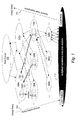
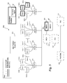
- Figure 1 is a block diagram illustrating clusters formed and aggregated at multiple levels of a logical hierarchy, according to an embodiment of the invention
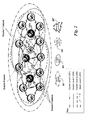
- Figure 2 is a block diagram illustrating an alternative representation of the hierarchical network, according to an embodiment of the invention.
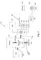
- Figure 3 is a block diagram of an exemplary node architecture, according to an embodiment of the invention.
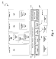
- FIG. 4 is a block diagram of an exemplary node having virtualization technology (VT) architecture, according to an embodiment of the invention.
- VT virtualization technology
- FIG. 5 is a block diagram of an exemplary node having platform resource layer (PRL), or embedded partition, architecture, according to an embodiment of the invention
- Figure 6 is a block diagram of an exemplary virtualization platform where a promotion agent resides in a virtual machine monitor
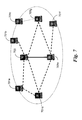
- Figure 7 is a diagram of a cluster hierarchy where the cluster's sub-network does not experience external influences to its topological configuration, according to embodiments of the invention.
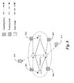
- Figure 8 depicts a cluster hierarchy where OverMesh nodes are entering the environment and departing the environment, according to embodiments of the invention
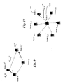
- Figure 9 shows a sample of relative dependency at a node, according to embodiments of the invention.
- Figure 10 shows node dependability relationships according embodiments of the invention.
- An embodiment of the present invention is a system and method relating to a novel framework to build a new class of network control (policy) and (state) management services.
- the framework may be used to build a number of self-management services to support decentralized (mesh) networks.
- the present invention is intended to hybridize centralized and decentralized network models to generate a more stable and robust network environment using clustering.
- Embodiments of the present invention may be applied to decentralized networks, such as mesh networks or peer-to-peer networks. Because of the complexity of these types of networks, a new approach for control and management is required. Embodiments of the invention, as more thoroughly described below, solve some of the management problems of existing large decentralized networks by utilizing merits of both the centralized and decentralized models.
- a sensor network uses small devices, for instance, body sensors, environmental sensors, facility sensors, etc. to gather information and provide the information to a centralize location for analysis.
- a wireless mesh network typically does not use an infrastructure for communication. In a wireless mess network, a variety of client devices just communicate with each other in a peered fashion. Thus, when a device is off the network, the other network devices may still communicate with one another.
- a peer-to-peer network is not based on communication peering, but based on computing peering.
- embodiments of the present invention improve upon these models melding aspects of both centralized and decentralized framework using both centralized control and decentralized control along with centralized state management and decentralized state management.
- self-promotion and autonomic promotions and reorganization of the cluster hierarchy are utilized.
- Embodiments of the present invention utilize a virtual clustering approach to traditional network control and management.
- This is a hybrid model of centralized and decentralized management and control.
- Clusters are formed and aggregated at multiple levels of a logical hierarchy, as shown in Figure 1 .
- the physical network nodes 110 are at the bottom of the hierarchy and do not (on a physical level) participate in the clustering schematic.
- the nodes in the physical network layer 110 may be seen as decentralized nodes. At this layer 110, the nodes are peered, with no centralized system or control.
- the arrow 101 on the right represents states or network management states. Behavior is occurring in the network and the states of the nodes rises and aggregates up through clusters of nodes.
- the arrow 103 on the left represents policy. For instance, if the system is operating inefficiently, policies are enforced down to the nodes from cluster-heads at a higher level, in order to control the system to make cause it to operate more efficiently. Autonomic systems often use this representation as illustration, e.g., state and control. In effect, there is a sensing side 101 and an actuation side 103.
- Network providers build hierarchical systems. However, these systems are physically hierarchical. Thus, once the system is built and statically defined, it stays at a status quo until a human physically makes a change to the network, for instance, adding a node or device.
- Communication systems and computing systems are often built on a physical hierarchical framework. They are physically oriented. In decentralized systems, there is often a flux, but no control or authority. Further, clustering that is used today seems to be directed to transportation of data, rather than control and management of the network hierarchy.
- structure in the system is created using a virtual model, rather than a physical model, specifically, using virtual clustering.
- Virtual clustering may be accomplished in multiple ways.
- Embodiments of the invention implement the virtual clusters using overlays or distributed virtual machines (DVMs).
- Clustering may be used to balance between the merits of decentralized management organizational strategy and a purely centralized organizational strategy. By organizing state management and control policies over hierarchies of clusters, merits of the peer-to-peer dynamics and more centralized dynamics may be achieved in a progression towards the root of the cluster 150 hierarchical tree.
- Cluster level 0 root level 150
- Cluster level 1 140a-b
- Cluster level 2 130a-c
- Cluster level 3 120a-c
- Cluster level n 4 110.
- Each cluster level has a cluster-head.
- Each node within a cluster also logically belongs to the clusters below as it is promoted upward. Even if a node has been promoted to a higher cluster, it still has functional responsibilities within the clusters below it.
- a cluster, for instance, 140a will comprise one leader (cluster-head 141) and leaders from the clusters below, for instance 131 and 133.
- Cluster-head 141 is also a cluster-head for cluster 130a below it in the hierarchy, as well as other lower level clusters (not shown).
- the cluster 140a comprises leaders from 130a, 130b and 130c (141, 131, and 133, respectively).
- the node that rises to leader of the root cluster would be the most operationally resilient node in the network.
- Each cluster comprises a subset of the nodes in the decentralized system 110, so the clusters are easier to control and optimize - there is less chaos.
- cluster-head 141 may communicate with nodes in cluster 140a and 130a, but has no direct knowledge or control of cluster 140b.
- Cluster-head 141 also has no visibility into the root cluster 150, unless promoted into that cluster. It may be seen that node 141 is a cluster-head of both cluster 130a and 140a.
- Nodes 131 and 133 are cluster-heads of clusters 130b and 130c, respectively, by only peer nodes in cluster 140a, at the higher level, and subordinate to node 141.
- Clusters are proxy'ed by the promoted cluster-head, and cluster-heads act on behalf of the cluster.
- the cluster-head is leading, participating in the depth (tree), breadth (level) and specific cluster they are heading. This reduces the level of complexity in node communications, as only the cluster-head needs to be involved in control and management communication outside of the cluster; the cluster-head represents the cluster, as if it were a single node.
- self-organizing properties may be introduced at each level of the hierarchy and such behaviors may be consolidated to respective clusters, albeit with policy and state influences from peered, parent (global) and child (local) clusters. Since, there exists multiple, logical levels or overlays of clustering, the higher level clusters and cluster-heads will be formed of underlying cluster-heads, not physical nodes. It should be noted that the cluster-head at the root level, and all underlying levels, is not tied to a specific physical node. The sensing of operational efficiencies triggers actuation and fluctuation of the nodes' promotion and demotion within the system. More resilient nodes rise and less resilient nodes will fall in the hierarchy.
- the information required to cause the actuation of change based on the collected states is distributed among the nodes in the cluster, rather than residing in a single database under control of one central server. Not all of the nodes will have all of the information. Nodes receive relevant information. If a node n participates in a cluster C, then node n will have information relating to cluster C.
- a Clustering Manager is a distributed overlay, or distributed virtual machine (DVM), service managing the depth and breadth of the cluster hierarchy.
- the CM may be distributed on a subset of nodes, however the ability to participate is afforded to all nodes. In general, trust and truthfulness are expected, but in the context of CM, the operational decisions are handled as one entity, not consensus, but by global state synchronization. Specific functions of cluster addressing, clustering operations and cluster-head selections are managed through the CM.
- the CM is a lightweight service function that facilitates the entire life-cycle of the logical clustering hierarchy supporting the physical domain of network nodes.
- This life-cycle includes coordinating the grouping or regrouping of network nodes through cluster addressing facilitation, inter-cluster node (mobile) movement or the creation and breakdown of clusters, as needed.
- the CM serves the control management functions primarily to coordinate the hierarchical organization of the clustering operations and management.
- cluster-heads may be based on operational superiority or rank. Similar to military or corporate rank, the basis of higher ranked cluster-head nodes is established by the ability of nodes to be highly networked, highly reliable, stable and superior performers. In other words, nodes which exhibit higher (a) reachability, (b) stability and (c) performance efficiency are to be promoted to cluster-heads.
- This self-organized positioning is not unlike the human organization of network nodes in a traditional hierarchical telecommunications network, where nodes at the core of the network must exhibit high availability (e.g., five nines), demonstrate high reachability capability and extremely low latency.
- i.) reachability state, ii.) stability state, and iii.) performance state will be the quantitative ordering basis for determining operational rank and superiority.
- a network may be initially created with virtual clusters using some other, artificial criteria, such as highest address results in highest rank.
- criteria such as highest address results in highest rank.
- the natural progression of using reachability, stability and performance efficiency to determine promotion and demotion will ultimately result in an optimized network, at least for these criteria. It is contemplated that other criteria may be used, or weighted differently for networks of different types.
- the system relies on truthfulness of the nodes. For instance, when a node declares itself superior, the other nodes will agree. In other embodiments, the system relies on nodes watching the performance of other nodes in the cluster. In this case, other nodes may offer to rank a node. Nodes are able to rank the reachability of other nodes.
- a stable system may have many levels and be asymmetrical. It is contemplated that depending on the problem set to be solved by the network, various hierarchies or varying levels may emerge. For instance, for systems performing fault management, it may be that fewer levels are more efficient. Different strategies may be used for different management and control systems. It may be desirable for a large data center requiring the five nines of for up-time to be weighted more in the stability criteria for promotion. For a DNS server system, perhaps reachability will be more weighted for promotion. It is also contemplated that regardless of the weighting of the variables that clustering will naturally result. This type of clustering has been shown to be natural in statistical systems.
- a single cluster addressing scheme exists across the cluster hierarchy.
- the lowest level of the tree does participate in the clustering management activities; however, for completeness, this network addressing is maintained and can be used, for example, for physical network service broadcasting purposes.
- any cluster in the hierarchy will be labeled C(n, m).
- the eventual highest or root cluster is assigned C(0,0).
- clusters level partitioning may not necessarily follow or reflect a symmetrical tree hierarchy; that is, each cluster level may converge to a number of clusters fewer than the number of clusters below its level, depending on the system dynamics of the environment.
- network nodes (at the lowest level n ) or cluster-heads (at levels ⁇ n ) assigned to a particular cluster will use C(n, m) to communicate with nodes (or cluster-heads) in this particular cluster, or specifically, the cluster-head assigned to manage the C ( n , m ).
- Cluster nodes or cluster-heads associated with a parent cluster may use the cluster address for sinking and responding to cluster operational communications, but only the global cluster-head may utilize the cluster address for sourcing operational communications or clustering control or management.
- only global cluster-heads can participate in inter-cluster and intra-cluster communications and can directly influence the global behavior of the cluster, peers or child clusters.
- Other nodes or cluster-heads (associated to this global cluster) may influence indirectly, but only via their intra-cluster (local) participation as members of the global cluster.
- the addressing scheme supports multicasting across cluster-heads, where C(n,-) communicates to all peer cluster-heads at level n .
- cluster-heads are the only nodes in a cluster that are aware of the hierarchy lineage, and therefore communicate via their lineage and peer cluster-heads; thus, they are not aware of the broader set of clusters outside their level and lineage.
- a cluster-head which continues to operationally dominate in the emergent hierarchy up to, and assigned the root cluster C(0,0), does have the ability to communicate and possibly access state or policy across all clusters in the hierarchy.
- Inter-cluster and intra-cluster communications occur according to specific addresses assigned to cluster-heads as described above. It will be understood by those of skill in the art after reading this disclosure that an overlay structure for accomplishing cluster virtual networking may be based on any number of schemes. In general, messaging will appear peer-to-peer in the overlay; however logically, the operational messaging will support state and policy-based communications and will occur in intra-cluster, inter-cluster in hierarchical or peer form based on the clustering structure. Control (policy) and management (state) messages will be asynchronous and will support cooperative, aggregation and peering algorithms as discussed in the upcoming sections.
- the objectives of the clusters are to facilitate network control and management through a balance of peer-to-peer and hierarchical organizational control.
- the state management functions may include stability, optimization and connectivity state management, for example.
- Cluster-head nodes receive cluster state conditions and perform aggregation and correlation within their respective clusters or cluster nodes (i.e., cluster-heads beyond level n).
- Cluster-heads perform cluster state analysis through statistical computing techniques, holding cluster knowledge for state-level assimilation with peer clusters.
- Cluster state is propagated upward to global cluster-heads, or acted upon though the integration of local and global policy using policy-based reinforcement to control or influence the local cluster behavior.
- control and management behavior novelty is exhibited independently between cluster levels with both temporal and spatial (state, policy) aggregation occurring.
- the spatial aggregation represents or accounts for the multiple local clusters affiliated with the global cluster, while temporal aggregation accounts for the cycle periods that local clusters follow.
- temporal aggregation accounts for the cycle periods that local clusters follow.
- a long standing design choice in the information technology (IT) network control and management community is the level of centralized or decentralized control or management that may be designed into network management or policy-based management tools. While there are advantages and disadvantages to both architectural choices, embodiments of the present invention call for an entirely new approach based on a virtual clustering methodology, previously applied to peer-to-peer and sensor-based networking systems. Thus, clustering, as an architectural choice, is used to balance between the merits of decentralized organizational strategy and a purely centralized organizational strategy for both state management and policy-based management. (See Figure 1 ).
- Organizing state management and control policies over hierarchies of clusters of decentralized dynamics at the lower portion of the hierarchy and more centralized dynamics while progressing towards the root of the tree, enable the merits of a hybrid network to be achieved.
- the parent-to-child cluster separation properties are created at each level of the hierarchy and self-organizing behaviors may be consolidated to respective clusters, albeit with policy and state influences from peered, parent or child clusters.
- the overhead of distributed management and control are localized without compromising the benefits of global, distributed control and management.
- a cluster-head will act as a central function to facilitate central management within each, respective cluster.
- Clusters of nodes in Cluster level 0 are surrounded by a broken line interspersed with two dots 201.
- Cluster level 1 is represented by a broken dotted line 203.
- Cluster level 2 is represented by a grey dashed line 205, and the mesh level 3 is represented by arrowed lightening bolts 207.
- the cluster heads, or leaders are shown.
- Cluster 0 leader 210 is also a leader of Cluster 1 (along with 220), and Cluster 2 (along with 230a, 220, and 230b).
- a network designer may choose to use more criteria, e.g., in addition to reachability, stability and performance efficiency, or a subset thereof, in order to effect self-promotion. Other combinations of factors may be optimal for some networks, or preferred for cost or maintenance reasons.
- FIG 3 is a block diagram of an exemplary node architecture 300.
- Processor 310 communicates with a memory controller hub (MCH) 314, also known as North bridge, via the front side bus 301.
- MCH memory controller hub
- the MCH 314 communicates with system memory 312 via a memory bus 303.
- the MCH 314 may also communicate with an advanced graphics port (AGP) 316 via a graphics bus 305.
- AGP advanced graphics port
- the MCH 314 communicates with an I/O controller hub (ICH) 320, also known as South bridge, via a peripheral component interconnect (PCI) bus 307.
- ICH I/O controller hub
- PCI peripheral component interconnect
- the ICH 320 may be coupled to one or more components such as PCI hard drives (not shown), legacy components such as IDE 322, USB 324, LAN 326 and Audio 328, and a Super I/O (SIO) controller 356 via a low pin count (LPC) bus 356.
- PCI hard drives not shown
- legacy components such as IDE 322, USB 324, LAN 326 and Audio 328
- SIO Super I/O
- LPC low pin count
- Processor 310 may be any type of processor capable of executing software, such as a microprocessor, digital signal processor, microcontroller, or the like. Though Figure 3 shows only one such processor 310, there may be one or more processors in platform hardware 300 and one or more of the processors may include multiple threads, multiple cores, or the like.
- Memory 312 may be a hard disk, a floppy disk, random access memory (RAM), read only memory (ROM), flash memory, or any other type of medium readable by processor 310. Memory 312 may store instructions for performing the execution of method embodiments of the present invention.
- Non-volatile memory such as Flash memory 352 may be coupled to the IO controller via a low pin count (LPC) bus 309.
- LPC low pin count
- BIOS firmware 354 typically resides in the Flash memory 352 and boot up will execute instructions from the Flash, or firmware.
- platform 300 is a server enabling server management tasks.
- This platform embodiment may have a baseboard management controller (BMC) 350 coupled to the ICH 320 via the LPC 309.
- platform 300 may have a microprocessor or "manageability engine” (ME) controller 330 coupled to the ICH 320.
- ME controller 330 may be an Intel® Active Management Technology (iAMT) architecture.
- the BMC 350 or the iAMT 330 may execute network services to determine the (a) reachability, (b) stability and (c) performance efficiency of the platform 300 to assist in identifying whether the node should be promoted to a cluster-head, and how high in the hierarchy it will be promoted. It should be noted that each level of the hierarchy operates independently to the higher level, and has no visibility or awareness to upper levels. Thus, promotion is specific to one level only.
- FIG. 4 is a block diagram of an exemplary node having virtualization technology (VT) architecture, according to an embodiment of the invention.
- Figure 4 is a block diagram illustrating traditional hypervisor virtual machine monitor (VMM) architecture platform 400.
- a number of guest virtual machines (VMs) 401, 403, 405, and 407 may be running on the platform 400 at the same time.
- a VMM 410 controls the guest VMs' access to the hardware 420 via the processor/platform virtualization layer 411.
- a number of virtual device models 413 and 415 may exist within the VMM 410.
- the VMM 410 may operate at the highest privilege level.
- the VMM 410 controls access to the file system 417, memory and all devices, as discussed further below.
- the VMM 410 typically has a device driver 419 for each hardware device on the platform.
- the VMM 410 and guest VMs 401, 403, 405 and 407 execute on platform hardware 420.
- the platform hardware 420 may include a processor 422, memory 424 and one or more I/O devices 426 and 428.
- the platform hardware 420 may be a personal computer (PC), mainframe, handheld device, portable computer, set top box, or any other computing system.
- Processor 422 may be any type of processor capable of executing software, such as a microprocessor, digital signal processor, microcontroller, or the like. Though Figure 4 shows only one such processor 422, there may be one or more processors in platform hardware 420 and one or more of the processors may include multiple threads, multiple cores, or the like.
- Memory 424 may be a hard disk, a floppy disk, random access memory (RAM), read only memory (ROM), flash memory, or any other type of medium readable by processor 422. Memory 424 may store instructions for performing the execution of method embodiments of the present invention.
- the one or more I/O devices 426 and 428 may be, for example, network interface cards, communication ports, video controllers, disk controllers on system buses (e.g., Peripheral Component Interconnect (PCI), Industry Standard Architecture (ISA), Advanced Graphics Port (AGP)), devices integrated into the chipset logic or processor (e.g., real-time clocks, programmable timers, performance counters), or any other device on the platform hardware 420.
- the one or more I/O devices 426 and 428 may be accessed through I/O instructions, or memory mapped I/O accesses or through any other means known in the art.
- a virtual machine (VM) in the platform 400 may execute network services to determine the (a) reachability, (b) stability and (c) performance efficiency of the platform 400 to assist in identifying whether the node should be promoted to a cluster-head, and how high in the hierarchy it will be promoted.
- this VM may be a virtual appliance running at an elevated level of security, and in others it may be simply be running in a guest VM.
- FIG. 5 is a block diagram of an exemplary node having platform resource layer (PRL), or embedded partition, architecture, according to an embodiment of the invention.
- PRL platform resource layer
- FIG. 5 there is shown an exemplary block diagram of a PRL architecture, according to embodiments of the invention.
- components that are available to the main partition 510 are drawn with solid blocks.
- Components available to the embedded, or system partition 520 are drawn with bold, solid blocks.
- Components available to both partitions are drawn with a block alternating with dots and dashes.
- a platform, or node has four multi-core processors in Sockets 0-3 (531-534). While this example shows only four processor sockets, it will be apparent to one of ordinary skill in the art that various configurations of processors and cores may be used to practice embodiments of the invention.
- Socket 0 (531) may have four processing cores 535a-d.
- the illustrated embodiment has 16 effective processors on the platform (e.g., four sockets with four cores in each socket).
- Sockets 0-2 (531-533) are available only to the main partition 510.
- Socket 3 (534) is available to both the main partition 510 and to the embedded partition 520.
- core 0 is available only to the main partition 510, and cores 1-3 are available only to the embedded partition 520.
- the embedded partition 520 may have a promotion agent, or clustering manager, 521, as more fully discussed above and below.
- the embedded partition may also comprise other agents or services, for instance, for determining reachability, stability and performance efficiency. These services may be part of a same embedded partition, or be segregated into one or more separate partitions. For a node that is a member, or cluster-head of multiple virtual clusters, there may be multiple instances (not shown) of a promotion agent, or other services, running for each cluster of which the node is a member.
- the platform has a memory controller hub (MCH) 501 (also known as north bridge) coupled to memory 502.
- Memory 502 may have two partitions MEM1 (503) and MEM2 (505).
- Memory partition MEM1 (503) is available only to the embedded partition and memory partition MEM2 (505) is available only to the main partition.
- the chipset containing the MCH is configured to partition the memory using hardware constructs, in contrast to a VMM solution which uses software constructs.
- memory 502 may be a hard disk, a floppy disk, random access memory (RAM), read only memory (ROM), flash memory, or any other type of medium readable by processor.
- Memory 502 may store instructions for performing the execution of embodiments of the present invention. While only two partitions are shown in this example, it will be understood that there may be more than one guest OS, each running in its own partition.
- the MCH 501 may communicate with an I/O controller hub (ICH) 507, also known as South bridge, via a peripheral component interconnect (PCI) bus.
- the ICH 507 may be coupled to one or more components such as PCI hard drives, legacy components such as IDE, USB, LAN and Audio, and a Super I/O (SIO) controller via a low pin count (LPC) bus (not shown).
- the ICH 507 is shown coupled to a hard disk drive 509 and to a network interface controller (NIC) 511.
- NIC network interface controller
- the MCH 501 is configured to control accesses to memory and the ICH 507 is configured to control I/O accesses.
- the chipset is configured by the firmware, upon boot, to partition the various resources on the platform. In some cases, there may be only one partition and the platform acts like a legacy platform in most respects. In the example shown, there are two partitions, a main partition 510 and an embedded partition 520. Each partition designated is given a unique partition identifier (ID).
- an embedded partition configuration when a device sends an alert, the chipset may properly route the alert to the appropriate partition, as this information is encoded at boot time.
- the hardware passes the device alerts to the VMM (virtualized devices) and the software routes the information appropriately to the various virtual machines.
- An embedded partition may act as hardware assisted virtualization.
- a promotion agent may be embodied within a VMM which controls all guest virtual machines (VMs) and guest operating systems (OS's) running on the platform.
- the promotion agent is embodied in a privileged partition, process or hypervisor that controls I/O requests for individual OS's.
- the promotion agent measures activities and performance data to determine the (a) reachability, (b) stability and (c) performance efficiency of the platform 500. This determination allows the node 500 to self-promote or at least pass its metrics on to another node, perhaps a cluster head, to determine whether or not to promote node 500 to a higher cluster level.
- a virtual machine (VM) 610 has a guest OS 611.
- Various user applications 613 may run under the guest OS 611.
- the OS has device drivers 615 which may be virtualized within the VMM 620.
- Access to platform hardware 630 will require the use of the VMM.
- a promotion agent 621 within the VMM 620 may measure activities and performance data to determine the (a) reachability, (b) stability and (c) performance efficiency of the platform 600. This determination allows the node 600 to self-promote or at least pass its metrics on to another node, perhaps a cluster head, to determine whether or not to promote node 600 to a higher cluster level.
- a platform partition, or more privileged partition 640 having its own OS 641, user applications 643, device drivers 645 is shown.
- This platform partition may also have virtualized devices via the VMM 620.
- the VMM is shown to comprise a promotion agent.
- the promotion agent may execute within a VM on the platform.
- the VMM or individual VMs may also comprise other agents or services, for instance, for determining reachability, stability and performance efficiency. These services may be part of a same VM, or be distributed into one or more separate VMs.
- agents or services for instance, for determining reachability, stability and performance efficiency. These services may be part of a same VM, or be distributed into one or more separate VMs.
- the reachability, stability and performance efficiency service may be part of the promotion agent, or separate services being used for a variety of management purposes.
- a node may be part of clusters at both cluster level 0 and cluster level 1.
- a separate instance of a promotion agent may exist for each cluster level 451 and 453. In some embodiments, these instances may be run in different VMs, or partitions, 405 and 407. In other embodiments, multiple instances may run in the same VM, partition or VMM.
- the promotion agent may require the use of a specific service or agent to provide reachability 455, stability 457 and performance efficiency 459 data. These agents may run in a same partition or VM, or in a different partition or VM.
- the services may be imbedded within the promotion agent, or other component requiring their services.
- a reachability agent 455, stability agent 457 and a performance efficiency agent 459 are shown as separate agents running in the same VM 403. It will be understood by those of skill in the art after reviewing the description herein, that various permutations and embodiments may be implemented, within the scope of the disclosed inventions.
- a virtualization platform may have a virtual appliance, or secure VM or service operation system (SOS), and one or more capability operating systems (COS) or user environments.
- the agents may all run in the same virtual appliance or (SOS).
- each cluster can reach a level of stability, independently, to the broader portions of the network, by ensuring a relatively uniform level of operational disparity with other nodes or cluster-heads within the same cluster by maintaining a static topology configuration and operational uniformity across the cluster during one or more measurement cycles.
- external node dynamics can reduce the level of instability, either through the reduction (departure) of unstable nodes or increase (arrival) of more stable nodes, relative to the other nodes or cluster-heads within the same cluster.
- the entropy formulations consider both dynamics - imitating the equalization and dissipation behaviors of both isolated (intra-cluster) systems and open systems (inter-cluster) in thermodynamic systems, respectively.
- Figures 7 and 8 depict these influences.
- node 703 is a cluster-head and nodes 701 a-g are subordinate nodes within the cluster.
- This cluster is fairly static, with no migration of nodes in or out of the cluster.
- Figure 8 depicts a cluster hierarchy where OverMesh nodes are entering the environment (801, 803, 805, 807), represented by double cross-hatched nodes, and departing the environment (811, 813), represented by a single hatched node. In both cases, the cluster's aggregate entropy can reflect a level of equilibrium and nodes of equilibrium based on their relative measures of statistical availability or reliability between the nodes.
- service dependability may have multiple stability or environmental constraints with local node and link impact, but more importantly on applications and network services that traverse multiple OverMesh nodes. From the standpoint of the self-organizing cluster, characterizing the level of dynamics or stability across the cluster is of concern, given such constraints. Therefore, one can use a combined metric to characterize the degree of service dependability between nodes, or choose to be selective to the most critical constraint (e.g., node availability) in characterizing cluster stability or entropy.
- most critical constraint e.g., node availability
- Table 1 is an example of constraints of concern, but is not exhaustive. For instance, a constraint of stability may be a high fading condition. Once measure of this condition is a loss rate, but there may be others. A measure of excessive load or congestion may be utilization, but other measures may be available, etc.
- a period between t 1 and t 2 of ⁇ T , , and D m, n ( ⁇ T) is defined for an entropy period, as the average relative dependability of node m with respect to node n at time t 2 , where m and n are both members of the same cluster C i,j ., and with the nodes exchanging relative dependability samples, d m, n ( ⁇ ) during multiple ⁇ intervals within the entropy period, ⁇ T .
- the actual dependability metric and measurement units is irrelevant, since only the relative dependability differences between the nodes is important. More specifically, both measures are defined below with the goal of eventually defining an entropy formulation for cluster, C i,j .
- the node changes are depicted in Figure 9 , where the change ⁇ reflects the interval of change, and a relative change in the service dependability are reflected for both node m and node n during the interval.
- N is equal to the number of samples in ⁇ T and t i is the discrete time at the end of each sample, ⁇
- H m ( t , ⁇ T ) is calculated as the entropy of node m during the specific period of entropy measurement ⁇ T in cluster C ij , normalized between [0,1].
- This representation of entropy is the desired measure of stability with respect to node m, in terms of the absolute relative dependability during the period of stability state evaluation, ⁇ T .
- entropy is small when the change in relative dependability variation shows higher perturbation, while a higher entropy value will show more relative stability.
- the entropy terms for the other nodes in cluster C ij . may be evaluated, similarly.
- a cluster may be seen as a virtual network.
- the cluster-head of a cluster C(n,m) may serve to control several clusters as cluster-head of clusters below which it has risen.
- each cluster's management and control services may run in a different virtual machine or in a different embedded partition.
- This implementation works best on platforms that have the capability to dynamically create new VMs or partitions.
- a cluster-head is promoted to a higher level cluster, a new VM or partition may be created to operate as management and control for the new cluster. This allows control and management of the distributed clusters to be segregated and protected from tampering or confusion with other cluster activities.
- Other architectures may be favored, for instance, multi-threading and multi-core architectures where cluster management may be segregated to different threads or cores.
- a VM, partition or thread that was used for control and management of the cluster above may be deactivated or deleted.
- sensing of reliability, stability and performance metrics may also be performed in a separate VM, virtual appliance, partition, core or thread.
- This component may make the promotion/demotion decision, or the results of the collection and/or evaluation of data may then be provided to another VM, virtual appliance, partition, core or thread which makes the ultimate decision for promotion/demotion.
- the techniques described herein are not limited to any particular hardware or software configuration; they may find applicability in any computing, consumer electronics, or processing environment.
- the techniques may be implemented in hardware, software, or a combination of the two.
- program code may represent hardware using a hardware description language or another functional description language which essentially provides a model of how designed hardware is expected to perform.
- Program code may be assembly or machine language, or data that may be compiled and/or interpreted.
- Each program may be implemented in a high level procedural or object-oriented programming language to communicate with a processing system.
- programs may be implemented in assembly or machine language, if desired. In any case, the language may be compiled or interpreted.
- Program instructions may be used to cause a general-purpose or special-purpose processing system that is programmed with the instructions to perform the operations described herein. Alternatively, the operations may be performed by specific hardware components that contain hardwired logic for performing the operations, or by any combination of programmed computer components and custom hardware components.
- the methods described herein may be provided as a computer program product that may include a machine accessible medium having stored thereon instructions that may be used to program a processing system or other electronic device to perform the methods.
- Program code, or instructions may be stored in, for example, volatile and/or non-volatile memory, such as storage devices and/or an associated machine readable or machine accessible medium including solid-state memory, hard-drives, floppy-disks, optical storage, tapes, flash memory, memory sticks, digital video disks, digital versatile discs (DVDs), etc., as well as more exotic mediums such as machine-accessible biological state preserving storage.
- volatile and/or non-volatile memory such as storage devices and/or an associated machine readable or machine accessible medium including solid-state memory, hard-drives, floppy-disks, optical storage, tapes, flash memory, memory sticks, digital video disks, digital versatile discs (DVDs), etc.
- machine-accessible biological state preserving storage such as machine-accessible biological state preserving storage.
- a machine readable medium may include any mechanism for storing, transmitting, or receiving information in a form readable by a machine, and the medium may include a tangible medium through which electrical, optical, acoustical or other form of propagated signals or carrier wave encoding the program code may pass, such as antennas, optical fibers, communications interfaces, etc.
- Program code may be transmitted in the form of packets, serial data, parallel data, propagated signals, etc., and may be used in a compressed or encrypted format.
- Program code may be implemented in programs executing on programmable machines such as mobile or stationary computers, personal digital assistants, set top boxes, cellular telephones and pagers, consumer electronics devices (including DVD players, personal video recorders, personal video players, satellite receivers, stereo receivers, cable TV receivers), and other electronic devices, each including a processor, volatile and/or non-volatile memory readable by the processor, at least one input device and/or one or more output devices.
- Program code may be applied to the data entered using the input device to perform the described embodiments and to generate output information. The output information may be applied to one or more output devices.
- embodiments of the disclosed subject matter can be practiced with various computer system configurations, including multiprocessor or multiple-core processor systems, minicomputers, mainframe computers, as well as pervasive or miniature computers or processors that may be embedded into virtually any device.
- embodiments of the disclosed subject matter can also be practiced in distributed computing environments where tasks or portions thereof may be performed by remote processing devices that are linked through a communications network.
Landscapes
- Engineering & Computer Science (AREA)
- Computer Networks & Wireless Communication (AREA)
- Signal Processing (AREA)
- Data Exchanges In Wide-Area Networks (AREA)
- Multi Processors (AREA)
- Computer And Data Communications (AREA)
- Mobile Radio Communication Systems (AREA)
- Two-Way Televisions, Distribution Of Moving Picture Or The Like (AREA)
- Storage Device Security (AREA)
- Information Transfer Between Computers (AREA)
Applications Claiming Priority (1)
| Application Number | Priority Date | Filing Date | Title |
|---|---|---|---|
| US11/864,805 US7996510B2 (en) | 2007-09-28 | 2007-09-28 | Virtual clustering for scalable network control and management |
Publications (4)
| Publication Number | Publication Date |
|---|---|
| EP2043298A2 true EP2043298A2 (de) | 2009-04-01 |
| EP2043298A3 EP2043298A3 (de) | 2009-04-29 |
| EP2043298B1 EP2043298B1 (de) | 2011-01-26 |
| EP2043298B8 EP2043298B8 (de) | 2011-04-13 |
Family
ID=40280670
Family Applications (1)
| Application Number | Title | Priority Date | Filing Date |
|---|---|---|---|
| EP08253154A Not-in-force EP2043298B8 (de) | 2007-09-28 | 2008-09-26 | Virtuelle Clusterbildung für skalierbare Netzwerksteuerung und Verwaltung |
Country Status (6)
| Country | Link |
|---|---|
| US (1) | US7996510B2 (de) |
| EP (1) | EP2043298B8 (de) |
| JP (1) | JP4981009B2 (de) |
| CN (1) | CN101414928B (de) |
| AT (1) | ATE497291T1 (de) |
| DE (1) | DE602008004711D1 (de) |
Cited By (4)
| Publication number | Priority date | Publication date | Assignee | Title |
|---|---|---|---|---|
| WO2011044944A1 (en) * | 2009-10-16 | 2011-04-21 | Nokia Siemens Networks Oy | Privacy policy management method for a user device |
| FR2987530A1 (fr) * | 2012-02-28 | 2013-08-30 | Sagemcom Energy & Telecom Sas | Reseau de dispositifs formant un systeme de diagnostic |
| WO2016033173A1 (en) * | 2014-08-26 | 2016-03-03 | Harper, Matthew, Hayden | Multi-node distributed network access server designed for large scalability |
| EP3410238A1 (de) * | 2017-06-02 | 2018-12-05 | Siemens Schweiz AG | Gruppierung von aktuatoren in einem gebäudeautomatisierungssystem |
Families Citing this family (53)
| Publication number | Priority date | Publication date | Assignee | Title |
|---|---|---|---|---|
| WO2005089239A2 (en) | 2004-03-13 | 2005-09-29 | Cluster Resources, Inc. | System and method of providing a self-optimizing reservation in space of compute resources |
| US8782654B2 (en) | 2004-03-13 | 2014-07-15 | Adaptive Computing Enterprises, Inc. | Co-allocating a reservation spanning different compute resources types |
| US20070266388A1 (en) | 2004-06-18 | 2007-11-15 | Cluster Resources, Inc. | System and method for providing advanced reservations in a compute environment |
| US8176490B1 (en) | 2004-08-20 | 2012-05-08 | Adaptive Computing Enterprises, Inc. | System and method of interfacing a workload manager and scheduler with an identity manager |
| US8271980B2 (en) | 2004-11-08 | 2012-09-18 | Adaptive Computing Enterprises, Inc. | System and method of providing system jobs within a compute environment |
| US9075657B2 (en) | 2005-04-07 | 2015-07-07 | Adaptive Computing Enterprises, Inc. | On-demand access to compute resources |
| US8863143B2 (en) | 2006-03-16 | 2014-10-14 | Adaptive Computing Enterprises, Inc. | System and method for managing a hybrid compute environment |
| US9231886B2 (en) | 2005-03-16 | 2016-01-05 | Adaptive Computing Enterprises, Inc. | Simple integration of an on-demand compute environment |
| EP1866767B1 (de) | 2005-03-16 | 2018-04-18 | III Holdings 12, LLC | Automatische übergabe von arbeitspensum an ein bedarfsdeckungszentrum |
| US8645514B2 (en) * | 2006-05-08 | 2014-02-04 | Xerox Corporation | Method and system for collaborative self-organization of devices |
| US8041773B2 (en) | 2007-09-24 | 2011-10-18 | The Research Foundation Of State University Of New York | Automatic clustering for self-organizing grids |
| US20090265449A1 (en) * | 2008-04-22 | 2009-10-22 | Hewlett-Packard Development Company, L.P. | Method of Computer Clustering |
| EP2294820A1 (de) * | 2008-05-28 | 2011-03-16 | Thomson Licensing | Hierarchisch geklustertes mehrkopf-peer-to-peer-live-streaming-system |
| US8997205B1 (en) * | 2008-06-27 | 2015-03-31 | Symantec Corporation | Method and apparatus for providing secure web transactions using a secure DNS server |
| US9842004B2 (en) * | 2008-08-22 | 2017-12-12 | Red Hat, Inc. | Adjusting resource usage for cloud-based networks |
| US8996909B2 (en) * | 2009-10-08 | 2015-03-31 | Microsoft Corporation | Modeling distribution and failover database connectivity behavior |
| US11720290B2 (en) | 2009-10-30 | 2023-08-08 | Iii Holdings 2, Llc | Memcached server functionality in a cluster of data processing nodes |
| US10877695B2 (en) | 2009-10-30 | 2020-12-29 | Iii Holdings 2, Llc | Memcached server functionality in a cluster of data processing nodes |
| US8966027B1 (en) * | 2010-05-24 | 2015-02-24 | Amazon Technologies, Inc. | Managing replication of computing nodes for provided computer networks |
| WO2012029146A1 (ja) * | 2010-09-01 | 2012-03-08 | 富士通株式会社 | 管理装置、管理プログラムおよび管理方法 |
| US8856784B2 (en) | 2011-06-14 | 2014-10-07 | Vmware, Inc. | Decentralized management of virtualized hosts |
| US9026630B2 (en) | 2011-06-14 | 2015-05-05 | Vmware, Inc. | Managing resources in a distributed system using dynamic clusters |
| US8701107B2 (en) | 2011-06-14 | 2014-04-15 | Vmware, Inc. | Decentralized management of virtualized hosts |
| US8717887B2 (en) * | 2011-08-08 | 2014-05-06 | Telefonaktiebolaget Lm Ericsson (Publ) | Scrambling code planning device and method for using same in wireless communication network |
| US9292350B1 (en) * | 2011-12-15 | 2016-03-22 | Symantec Corporation | Management and provisioning of virtual machines |
| US9032061B1 (en) | 2011-12-30 | 2015-05-12 | Emc Corporation | Policy based intelligent data placement |
| US8675672B1 (en) | 2011-12-30 | 2014-03-18 | Emc Corporation | Hierarchical cluster tree overlay network |
| US8861527B1 (en) * | 2011-12-30 | 2014-10-14 | Emc Corporation | Network-assisted routing for topology-aware overlay networks |
| CN102647418A (zh) * | 2012-04-01 | 2012-08-22 | 中国科学院上海应用物理研究所 | 一种控制系统环境的虚拟架构 |
| US9477529B2 (en) | 2012-06-20 | 2016-10-25 | International Business Machines Corporation | Job distributed within a grid environment using mega-host groupings of execution hosts based on resource attributes |
| US9449498B2 (en) * | 2012-08-17 | 2016-09-20 | Illinois Tool Works Inc. | Wireless communication network power optimization for control of industrial equipment in harsh environments |
| US9270520B2 (en) | 2012-08-17 | 2016-02-23 | Illinois Tool Works Inc. | Wireless communication network sensor information for control of industrial equipment in harsh environments |
| US10286475B2 (en) | 2012-08-17 | 2019-05-14 | Illinois Tool Works Inc. | Wireless communication network for control of industrial equipment in harsh environments |
| US9712947B2 (en) | 2012-08-17 | 2017-07-18 | Illinois Tool Works Inc. | Wireless communication network improved robustness for control of industrial equipment in harsh environments |
| US9119023B2 (en) | 2012-08-17 | 2015-08-25 | Illinois Tool Works Inc. | Wireless communication network association and security for control of industrial equipment in harsh environments |
| US9444748B2 (en) * | 2013-03-15 | 2016-09-13 | International Business Machines Corporation | Scalable flow and congestion control with OpenFlow |
| US9197601B2 (en) * | 2013-06-05 | 2015-11-24 | Bat Blue Networks, Inc. | System and method for providing a single global borderless virtual perimeter through distributed points of presence |
| US10038629B2 (en) | 2014-09-11 | 2018-07-31 | Microsoft Technology Licensing, Llc | Virtual machine migration using label based underlay network forwarding |
| US9794331B1 (en) * | 2014-09-29 | 2017-10-17 | Amazon Technologies, Inc. | Block allocation based on server utilization |
| US9923800B2 (en) | 2014-10-26 | 2018-03-20 | Microsoft Technology Licensing, Llc | Method for reachability management in computer networks |
| US9936014B2 (en) | 2014-10-26 | 2018-04-03 | Microsoft Technology Licensing, Llc | Method for virtual machine migration in computer networks |
| US9798567B2 (en) | 2014-11-25 | 2017-10-24 | The Research Foundation For The State University Of New York | Multi-hypervisor virtual machines |
| US10363627B2 (en) | 2014-12-16 | 2019-07-30 | Illinois Tool Works Inc. | Systems and methods for providing location services for a welding power supply |
| US10369652B2 (en) | 2015-07-24 | 2019-08-06 | Illinois Tool Works Inc. | Wireless and powerline communications in a welding-type system |
| KR101704638B1 (ko) * | 2015-09-03 | 2017-02-08 | 재단법인 실감교류인체감응솔루션연구단 | 병렬 필드 버스 네트워크 기반 모터 제어 시스템 |
| US9864624B2 (en) * | 2015-12-21 | 2018-01-09 | International Business Machines Corporation | Software-defined computing system remote support |
| WO2017176178A1 (en) * | 2016-04-05 | 2017-10-12 | Telefonaktiebolaget Lm Ericsson (Publ) | Method and agent for sharing information about cloudlet properties in distributed cloud environments |
| US10466984B2 (en) | 2017-05-01 | 2019-11-05 | At&T Intellectual Property I, L.P. | Identifying and associating computer assets impacted by potential change to a particular computer asset |
| WO2019171256A1 (en) * | 2018-03-05 | 2019-09-12 | Quanta Networks Inc. | Communications system and devices for routing data |
| US11016798B2 (en) | 2018-06-01 | 2021-05-25 | The Research Foundation for the State University | Multi-hypervisor virtual machines that run on multiple co-located hypervisors |
| US11269917B1 (en) | 2018-07-13 | 2022-03-08 | Cisco Technology, Inc. | Secure cluster pairing for business continuity and disaster recovery |
| CN109885684B (zh) * | 2019-01-31 | 2022-11-22 | 腾讯科技(深圳)有限公司 | 一种类簇处理方法及装置 |
| WO2020176525A1 (en) | 2019-02-25 | 2020-09-03 | Emory University | Systems, devices, and methods for autonomic formation of wireless networks |
Citations (2)
| Publication number | Priority date | Publication date | Assignee | Title |
|---|---|---|---|---|
| WO1998059462A1 (en) | 1997-06-19 | 1998-12-30 | Northern Telecom Limited | Architecture for network manager |
| WO2001082678A2 (en) | 2000-05-02 | 2001-11-08 | Sun Microsystems, Inc. | Cluster membership monitor |
Family Cites Families (37)
| Publication number | Priority date | Publication date | Assignee | Title |
|---|---|---|---|---|
| US5664106A (en) | 1993-06-04 | 1997-09-02 | Digital Equipment Corporation | Phase-space surface representation of server computer performance in a computer network |
| US5727051A (en) | 1995-07-14 | 1998-03-10 | Telefonaktiebolaget Lm Ericsson (Publ.) | System and method for adaptive routing on a virtual path broadband network |
| CA2190433A1 (en) | 1995-11-16 | 1997-05-17 | Nicholas W. Dawes | Method of determining the topology of a network of objects |
| US5918017A (en) * | 1996-08-23 | 1999-06-29 | Internatioinal Business Machines Corp. | System and method for providing dynamically alterable computer clusters for message routing |
| US6519660B1 (en) | 1999-09-28 | 2003-02-11 | International Business Machines Corporation | Method, system and program products for determining I/O configuration entropy |
| US6986137B1 (en) | 1999-09-28 | 2006-01-10 | International Business Machines Corporation | Method, system and program products for managing logical processors of a computing environment |
| US6711409B1 (en) | 1999-12-15 | 2004-03-23 | Bbnt Solutions Llc | Node belonging to multiple clusters in an ad hoc wireless network |
| US6829222B2 (en) | 2000-04-25 | 2004-12-07 | Board Of Regents The University Of Texas System | Clusterhead selection in wireless ad hoc networks |
| US7733818B2 (en) * | 2000-12-22 | 2010-06-08 | Terahop Networks, Inc. | Intelligent node communication using network formation messages in a mobile Ad hoc network |
| WO2002087172A1 (en) * | 2001-04-20 | 2002-10-31 | Motorola, Inc. | Protocol and structure for self-organizing network |
| US6877107B2 (en) | 2001-07-05 | 2005-04-05 | Softwired Ag | Method for ensuring operation during node failures and network partitions in a clustered message passing server |
| US6744740B2 (en) * | 2001-12-21 | 2004-06-01 | Motorola, Inc. | Network protocol for wireless devices utilizing location information |
| US7346056B2 (en) | 2002-02-01 | 2008-03-18 | Fujitsu Limited | Optimizing path selection for multiple service classes in a network |
| US7904556B2 (en) | 2002-03-05 | 2011-03-08 | Computer Associates Think, Inc. | Method and apparatus for role grouping by shared resource utilization |
| GB0205284D0 (en) | 2002-03-06 | 2002-04-17 | Lucent Technologies Inc | Entropy based complexity measurement for behaviour analysis of distributed self-organizing systems in telecommunication networks |
| US7277400B2 (en) | 2002-03-06 | 2007-10-02 | Lucent Technologies Inc. | Method of monitoring state of a telecommunications network comprising a plurality of nodes, and a corresponding telecommunications network |
| DE10214629A1 (de) * | 2002-04-02 | 2003-10-16 | Philips Intellectual Property | Verfahren zum Organisieren der Topologie eines Netzwerkes mit einer Vielzahl von Stationen, die in Cluster gruppiert sind |
| US7764617B2 (en) * | 2002-04-29 | 2010-07-27 | Harris Corporation | Mobile ad-hoc network and methods for performing functions therein based upon weighted quality of service metrics |
| US6788650B2 (en) * | 2002-06-06 | 2004-09-07 | Motorola, Inc. | Network architecture, addressing and routing |
| US20050152305A1 (en) * | 2002-11-25 | 2005-07-14 | Fujitsu Limited | Apparatus, method, and medium for self-organizing multi-hop wireless access networks |
| US20040100917A1 (en) | 2002-11-26 | 2004-05-27 | Perkins Matthew R. | Coordinator device election process for wireless sensor networks |
| US20040156388A1 (en) | 2003-02-07 | 2004-08-12 | Lockheed Martin Corporation | System for maintaining quality of service |
| US7962914B2 (en) | 2003-11-25 | 2011-06-14 | Emc Corporation | Method and apparatus for load balancing of distributed processing units based on performance metrics |
| JP4506387B2 (ja) * | 2004-09-30 | 2010-07-21 | ブラザー工業株式会社 | 情報通信システム、ノード装置、及びオーバーレイネットワーク形成方法等 |
| FI118291B (fi) * | 2004-12-22 | 2007-09-14 | Timo D Haemaelaeinen | Energiatehokas langaton anturiverkko, solmulaitteita sitä varten sekä menetelmä tietoliikenteen järjestämiseksi langattomassa anturiverkossa |
| EP1705799A1 (de) | 2005-03-22 | 2006-09-27 | Fondazione Torino Wireless | Verfahren und System zur Informationsverarbeitung |
| US7440436B2 (en) * | 2005-05-13 | 2008-10-21 | Natural Lighting Systems, Inc. | Self-organizing multi-channel mesh network |
| WO2007002838A2 (en) | 2005-06-29 | 2007-01-04 | Trustees Of Boston University | Whole-network anomaly diagnosis |
| JP4473199B2 (ja) * | 2005-09-06 | 2010-06-02 | 日本電信電話株式会社 | 品質測定方法およびノード装置 |
| US8271412B2 (en) | 2005-12-21 | 2012-09-18 | University Of South Carolina | Methods and systems for determining entropy metrics for networks |
| US8566447B2 (en) | 2006-04-10 | 2013-10-22 | Bank Of America Corporation | Virtual service switch |
| US20070298821A1 (en) | 2006-06-21 | 2007-12-27 | Lockheed Martin Corporation | System for boolean network configuration of a wireless network |
| US7792137B2 (en) * | 2006-07-05 | 2010-09-07 | Abidanet, Llc | Self-organized and self-managed ad hoc communications network |
| US20080028472A1 (en) * | 2006-07-25 | 2008-01-31 | International Business Machines Corporation | Heterogeneous evolutionary self-formatting Internet protocols |
| US7894926B2 (en) | 2006-09-22 | 2011-02-22 | Pdf Solutions, Inc. | Global predictive monitoring system for a manufacturing facility |
| US7990927B2 (en) * | 2006-10-31 | 2011-08-02 | Infineon Technologies Ag | Method and apparatus for transmitting data in a communication system |
| US8041773B2 (en) * | 2007-09-24 | 2011-10-18 | The Research Foundation Of State University Of New York | Automatic clustering for self-organizing grids |
-
2007
- 2007-09-28 US US11/864,805 patent/US7996510B2/en not_active Expired - Fee Related
-
2008
- 2008-09-26 DE DE602008004711T patent/DE602008004711D1/de active Active
- 2008-09-26 JP JP2008248776A patent/JP4981009B2/ja not_active Expired - Fee Related
- 2008-09-26 AT AT08253154T patent/ATE497291T1/de not_active IP Right Cessation
- 2008-09-26 EP EP08253154A patent/EP2043298B8/de not_active Not-in-force
- 2008-09-28 CN CN2008101688668A patent/CN101414928B/zh not_active Expired - Fee Related
Patent Citations (2)
| Publication number | Priority date | Publication date | Assignee | Title |
|---|---|---|---|---|
| WO1998059462A1 (en) | 1997-06-19 | 1998-12-30 | Northern Telecom Limited | Architecture for network manager |
| WO2001082678A2 (en) | 2000-05-02 | 2001-11-08 | Sun Microsystems, Inc. | Cluster membership monitor |
Non-Patent Citations (1)
| Title |
|---|
| BEONGKU AN ET AL.: "An Entropy-Based Model for Supporting and Evaluating Route Stability in Mobile Ad hoc Wireless Networks", IEEE COMMUNICATIONS LETTERS, vol. 6, no. 8, 1 August 2002 (2002-08-01), pages 328 - 330 |
Cited By (7)
| Publication number | Priority date | Publication date | Assignee | Title |
|---|---|---|---|---|
| WO2011044944A1 (en) * | 2009-10-16 | 2011-04-21 | Nokia Siemens Networks Oy | Privacy policy management method for a user device |
| US9794268B2 (en) | 2009-10-16 | 2017-10-17 | Nokia Solutions And Networks Oy | Privacy policy management method for a user device |
| FR2987530A1 (fr) * | 2012-02-28 | 2013-08-30 | Sagemcom Energy & Telecom Sas | Reseau de dispositifs formant un systeme de diagnostic |
| WO2013127660A1 (fr) * | 2012-02-28 | 2013-09-06 | Sagemcom Energy & Telecom Sas | Réseau de dispositifs formant un système de diagnostic |
| US9672096B2 (en) | 2012-02-28 | 2017-06-06 | Sagemcom Energy & Telecom Sas | Network of devices forming a diagnostic system |
| WO2016033173A1 (en) * | 2014-08-26 | 2016-03-03 | Harper, Matthew, Hayden | Multi-node distributed network access server designed for large scalability |
| EP3410238A1 (de) * | 2017-06-02 | 2018-12-05 | Siemens Schweiz AG | Gruppierung von aktuatoren in einem gebäudeautomatisierungssystem |
Also Published As
| Publication number | Publication date |
|---|---|
| ATE497291T1 (de) | 2011-02-15 |
| EP2043298B1 (de) | 2011-01-26 |
| EP2043298B8 (de) | 2011-04-13 |
| CN101414928B (zh) | 2011-12-14 |
| CN101414928A (zh) | 2009-04-22 |
| US7996510B2 (en) | 2011-08-09 |
| US20090089300A1 (en) | 2009-04-02 |
| DE602008004711D1 (de) | 2011-03-10 |
| JP2009163710A (ja) | 2009-07-23 |
| JP4981009B2 (ja) | 2012-07-18 |
| EP2043298A3 (de) | 2009-04-29 |
Similar Documents
| Publication | Publication Date | Title |
|---|---|---|
| EP2043298B1 (de) | Virtuelle Clusterbildung für skalierbare Netzwerksteuerung und Verwaltung | |
| EP2393240B1 (de) | System und Verfahren zur entropiebasierten Stabilitätsverwaltung eines hierarchischen Netzwerks | |
| Sarmiento et al. | Decentralized SDN control plane for a distributed cloud-edge infrastructure: A survey | |
| US11740949B2 (en) | Distribution of events in edge devices | |
| Povedano-Molina et al. | DARGOS: A highly adaptable and scalable monitoring architecture for multi-tenant Clouds | |
| US11106560B2 (en) | Adaptive thresholds for containers | |
| US9081617B1 (en) | Provisioning of virtual machines using an N-ARY tree of clusters of nodes | |
| Mirmohseni et al. | Using Markov learning utilization model for resource allocation in cloud of thing network | |
| US8478878B2 (en) | Placement of virtual machines based on server cost and network cost | |
| US8107458B1 (en) | Power-based networking path allocation | |
| WO2012087767A2 (en) | Scheduling and management in a personal datacenter | |
| US8098658B1 (en) | Power-based networking resource allocation | |
| Mikkilineni et al. | The Turing O-Machine and the DIME Network Architecture: Injecting the Architectural Resiliency into Distributed Computing. | |
| Fernández-Cerero et al. | Sphere: Simulator of edge infrastructures for the optimization of performance and resources energy consumption | |
| US20160065680A1 (en) | Multi-node distributed network access server designed for large scalability | |
| CN109218138B (zh) | 网络节点监测方法及系统 | |
| US11271896B1 (en) | Aggregated group state for a group of device representations | |
| Liu et al. | A stratified monitoring model for hybrid cloud | |
| Graubner | Energy-efficient Transitional Near-* Computing | |
| Castro | Mechanisms for Latency Reduction in Fog Environments | |
| Celaya et al. | YA: Fast and Scalable Discovery of Idle CPUs in a P2P network. | |
| Balouek‐Thomert et al. | Nu@ ge: A container‐based cloud computing service federation | |
| Celaya et al. | Scalable architecture for allocation of idle CPUs in a P2P network | |
| Pérez Rico | Orchestration of distributed ingestion and processing of IoT data for fog platforms | |
| Rachapudi | Impact of user behavior on resource scaling in the XIFI node |
Legal Events
| Date | Code | Title | Description |
|---|---|---|---|
| PUAI | Public reference made under article 153(3) epc to a published international application that has entered the european phase |
Free format text: ORIGINAL CODE: 0009012 |
|
| PUAL | Search report despatched |
Free format text: ORIGINAL CODE: 0009013 |
|
| 17P | Request for examination filed |
Effective date: 20081022 |
|
| AK | Designated contracting states |
Kind code of ref document: A2 Designated state(s): AT BE BG CH CY CZ DE DK EE ES FI FR GB GR HR HU IE IS IT LI LT LU LV MC MT NL NO PL PT RO SE SI SK TR |
|
| AX | Request for extension of the european patent |
Extension state: AL BA MK RS |
|
| AK | Designated contracting states |
Kind code of ref document: A3 Designated state(s): AT BE BG CH CY CZ DE DK EE ES FI FR GB GR HR HU IE IS IT LI LT LU LV MC MT NL NO PL PT RO SE SI SK TR |
|
| AX | Request for extension of the european patent |
Extension state: AL BA MK RS |
|
| 17Q | First examination report despatched |
Effective date: 20090617 |
|
| AKX | Designation fees paid |
Designated state(s): AT BE BG CH CY CZ DE DK EE ES FI FR GB GR HR HU IE IS IT LI LT LU LV MC MT NL NO PL PT RO SE SI SK TR |
|
| GRAP | Despatch of communication of intention to grant a patent |
Free format text: ORIGINAL CODE: EPIDOSNIGR1 |
|
| GRAS | Grant fee paid |
Free format text: ORIGINAL CODE: EPIDOSNIGR3 |
|
| GRAA | (expected) grant |
Free format text: ORIGINAL CODE: 0009210 |
|
| AK | Designated contracting states |
Kind code of ref document: B1 Designated state(s): AT BE BG CH CY CZ DE DK EE ES FI FR GB GR HR HU IE IS IT LI LT LU LV MC MT NL NO PL PT RO SE SI SK TR |
|
| REG | Reference to a national code |
Ref country code: GB Ref legal event code: FG4D |
|
| REG | Reference to a national code |
Ref country code: CH Ref legal event code: EP |
|
| REG | Reference to a national code |
Ref country code: IE Ref legal event code: FG4D |
|
| REF | Corresponds to: |
Ref document number: 602008004711 Country of ref document: DE Date of ref document: 20110310 Kind code of ref document: P |
|
| REG | Reference to a national code |
Ref country code: DE Ref legal event code: R096 Ref document number: 602008004711 Country of ref document: DE Effective date: 20110310 |
|
| RAP2 | Party data changed (patent owner data changed or rights of a patent transferred) |
Owner name: INTEL CORPORATION |
|
| REG | Reference to a national code |
Ref country code: NL Ref legal event code: VDEP Effective date: 20110126 |
|
| LTIE | Lt: invalidation of european patent or patent extension |
Effective date: 20110126 |
|
| PG25 | Lapsed in a contracting state [announced via postgrant information from national office to epo] |
Ref country code: ES Free format text: LAPSE BECAUSE OF FAILURE TO SUBMIT A TRANSLATION OF THE DESCRIPTION OR TO PAY THE FEE WITHIN THE PRESCRIBED TIME-LIMIT Effective date: 20110507 Ref country code: LV Free format text: LAPSE BECAUSE OF FAILURE TO SUBMIT A TRANSLATION OF THE DESCRIPTION OR TO PAY THE FEE WITHIN THE PRESCRIBED TIME-LIMIT Effective date: 20110126 Ref country code: PT Free format text: LAPSE BECAUSE OF FAILURE TO SUBMIT A TRANSLATION OF THE DESCRIPTION OR TO PAY THE FEE WITHIN THE PRESCRIBED TIME-LIMIT Effective date: 20110526 Ref country code: NO Free format text: LAPSE BECAUSE OF FAILURE TO SUBMIT A TRANSLATION OF THE DESCRIPTION OR TO PAY THE FEE WITHIN THE PRESCRIBED TIME-LIMIT Effective date: 20110426 Ref country code: GR Free format text: LAPSE BECAUSE OF FAILURE TO SUBMIT A TRANSLATION OF THE DESCRIPTION OR TO PAY THE FEE WITHIN THE PRESCRIBED TIME-LIMIT Effective date: 20110427 Ref country code: IS Free format text: LAPSE BECAUSE OF FAILURE TO SUBMIT A TRANSLATION OF THE DESCRIPTION OR TO PAY THE FEE WITHIN THE PRESCRIBED TIME-LIMIT Effective date: 20110526 Ref country code: LT Free format text: LAPSE BECAUSE OF FAILURE TO SUBMIT A TRANSLATION OF THE DESCRIPTION OR TO PAY THE FEE WITHIN THE PRESCRIBED TIME-LIMIT Effective date: 20110126 Ref country code: SE Free format text: LAPSE BECAUSE OF FAILURE TO SUBMIT A TRANSLATION OF THE DESCRIPTION OR TO PAY THE FEE WITHIN THE PRESCRIBED TIME-LIMIT Effective date: 20110126 Ref country code: HR Free format text: LAPSE BECAUSE OF FAILURE TO SUBMIT A TRANSLATION OF THE DESCRIPTION OR TO PAY THE FEE WITHIN THE PRESCRIBED TIME-LIMIT Effective date: 20110126 |
|
| PG25 | Lapsed in a contracting state [announced via postgrant information from national office to epo] |
Ref country code: PL Free format text: LAPSE BECAUSE OF FAILURE TO SUBMIT A TRANSLATION OF THE DESCRIPTION OR TO PAY THE FEE WITHIN THE PRESCRIBED TIME-LIMIT Effective date: 20110126 Ref country code: SI Free format text: LAPSE BECAUSE OF FAILURE TO SUBMIT A TRANSLATION OF THE DESCRIPTION OR TO PAY THE FEE WITHIN THE PRESCRIBED TIME-LIMIT Effective date: 20110126 Ref country code: BE Free format text: LAPSE BECAUSE OF FAILURE TO SUBMIT A TRANSLATION OF THE DESCRIPTION OR TO PAY THE FEE WITHIN THE PRESCRIBED TIME-LIMIT Effective date: 20110126 Ref country code: AT Free format text: LAPSE BECAUSE OF FAILURE TO SUBMIT A TRANSLATION OF THE DESCRIPTION OR TO PAY THE FEE WITHIN THE PRESCRIBED TIME-LIMIT Effective date: 20110126 Ref country code: CY Free format text: LAPSE BECAUSE OF FAILURE TO SUBMIT A TRANSLATION OF THE DESCRIPTION OR TO PAY THE FEE WITHIN THE PRESCRIBED TIME-LIMIT Effective date: 20110126 Ref country code: NL Free format text: LAPSE BECAUSE OF FAILURE TO SUBMIT A TRANSLATION OF THE DESCRIPTION OR TO PAY THE FEE WITHIN THE PRESCRIBED TIME-LIMIT Effective date: 20110126 Ref country code: FI Free format text: LAPSE BECAUSE OF FAILURE TO SUBMIT A TRANSLATION OF THE DESCRIPTION OR TO PAY THE FEE WITHIN THE PRESCRIBED TIME-LIMIT Effective date: 20110126 Ref country code: BG Free format text: LAPSE BECAUSE OF FAILURE TO SUBMIT A TRANSLATION OF THE DESCRIPTION OR TO PAY THE FEE WITHIN THE PRESCRIBED TIME-LIMIT Effective date: 20110426 |
|
| PG25 | Lapsed in a contracting state [announced via postgrant information from national office to epo] |
Ref country code: DK Free format text: LAPSE BECAUSE OF FAILURE TO SUBMIT A TRANSLATION OF THE DESCRIPTION OR TO PAY THE FEE WITHIN THE PRESCRIBED TIME-LIMIT Effective date: 20110126 Ref country code: EE Free format text: LAPSE BECAUSE OF FAILURE TO SUBMIT A TRANSLATION OF THE DESCRIPTION OR TO PAY THE FEE WITHIN THE PRESCRIBED TIME-LIMIT Effective date: 20110126 |
|
| PG25 | Lapsed in a contracting state [announced via postgrant information from national office to epo] |
Ref country code: CZ Free format text: LAPSE BECAUSE OF FAILURE TO SUBMIT A TRANSLATION OF THE DESCRIPTION OR TO PAY THE FEE WITHIN THE PRESCRIBED TIME-LIMIT Effective date: 20110126 Ref country code: RO Free format text: LAPSE BECAUSE OF FAILURE TO SUBMIT A TRANSLATION OF THE DESCRIPTION OR TO PAY THE FEE WITHIN THE PRESCRIBED TIME-LIMIT Effective date: 20110126 Ref country code: SK Free format text: LAPSE BECAUSE OF FAILURE TO SUBMIT A TRANSLATION OF THE DESCRIPTION OR TO PAY THE FEE WITHIN THE PRESCRIBED TIME-LIMIT Effective date: 20110126 |
|
| PLBE | No opposition filed within time limit |
Free format text: ORIGINAL CODE: 0009261 |
|
| STAA | Information on the status of an ep patent application or granted ep patent |
Free format text: STATUS: NO OPPOSITION FILED WITHIN TIME LIMIT |
|
| 26N | No opposition filed |
Effective date: 20111027 |
|
| REG | Reference to a national code |
Ref country code: DE Ref legal event code: R097 Ref document number: 602008004711 Country of ref document: DE Effective date: 20111027 |
|
| PG25 | Lapsed in a contracting state [announced via postgrant information from national office to epo] |
Ref country code: MC Free format text: LAPSE BECAUSE OF NON-PAYMENT OF DUE FEES Effective date: 20110930 |
|
| PG25 | Lapsed in a contracting state [announced via postgrant information from national office to epo] |
Ref country code: IT Free format text: LAPSE BECAUSE OF FAILURE TO SUBMIT A TRANSLATION OF THE DESCRIPTION OR TO PAY THE FEE WITHIN THE PRESCRIBED TIME-LIMIT Effective date: 20110126 |
|
| REG | Reference to a national code |
Ref country code: IE Ref legal event code: MM4A |
|
| REG | Reference to a national code |
Ref country code: FR Ref legal event code: ST Effective date: 20120531 |
|
| PG25 | Lapsed in a contracting state [announced via postgrant information from national office to epo] |
Ref country code: IE Free format text: LAPSE BECAUSE OF NON-PAYMENT OF DUE FEES Effective date: 20110926 |
|
| PG25 | Lapsed in a contracting state [announced via postgrant information from national office to epo] |
Ref country code: FR Free format text: LAPSE BECAUSE OF NON-PAYMENT OF DUE FEES Effective date: 20110930 |
|
| PG25 | Lapsed in a contracting state [announced via postgrant information from national office to epo] |
Ref country code: MT Free format text: LAPSE BECAUSE OF FAILURE TO SUBMIT A TRANSLATION OF THE DESCRIPTION OR TO PAY THE FEE WITHIN THE PRESCRIBED TIME-LIMIT Effective date: 20110126 |
|
| REG | Reference to a national code |
Ref country code: CH Ref legal event code: PL |
|
| PG25 | Lapsed in a contracting state [announced via postgrant information from national office to epo] |
Ref country code: LU Free format text: LAPSE BECAUSE OF NON-PAYMENT OF DUE FEES Effective date: 20110926 |
|
| PG25 | Lapsed in a contracting state [announced via postgrant information from national office to epo] |
Ref country code: LI Free format text: LAPSE BECAUSE OF NON-PAYMENT OF DUE FEES Effective date: 20120930 Ref country code: CH Free format text: LAPSE BECAUSE OF NON-PAYMENT OF DUE FEES Effective date: 20120930 |
|
| PG25 | Lapsed in a contracting state [announced via postgrant information from national office to epo] |
Ref country code: TR Free format text: LAPSE BECAUSE OF FAILURE TO SUBMIT A TRANSLATION OF THE DESCRIPTION OR TO PAY THE FEE WITHIN THE PRESCRIBED TIME-LIMIT Effective date: 20110126 |
|
| PG25 | Lapsed in a contracting state [announced via postgrant information from national office to epo] |
Ref country code: HU Free format text: LAPSE BECAUSE OF FAILURE TO SUBMIT A TRANSLATION OF THE DESCRIPTION OR TO PAY THE FEE WITHIN THE PRESCRIBED TIME-LIMIT Effective date: 20110126 |
|
| PGFP | Annual fee paid to national office [announced via postgrant information from national office to epo] |
Ref country code: LU Payment date: 20170524 Year of fee payment: 13 |
|
| GBPC | Gb: european patent ceased through non-payment of renewal fee |
Effective date: 20180926 |
|
| PG25 | Lapsed in a contracting state [announced via postgrant information from national office to epo] |
Ref country code: GB Free format text: LAPSE BECAUSE OF NON-PAYMENT OF DUE FEES Effective date: 20180926 |
|
| PGFP | Annual fee paid to national office [announced via postgrant information from national office to epo] |
Ref country code: DE Payment date: 20200916 Year of fee payment: 13 |
|
| REG | Reference to a national code |
Ref country code: DE Ref legal event code: R079 Ref document number: 602008004711 Country of ref document: DE Free format text: PREVIOUS MAIN CLASS: H04L0012240000 Ipc: H04L0041000000 |
|
| REG | Reference to a national code |
Ref country code: DE Ref legal event code: R119 Ref document number: 602008004711 Country of ref document: DE |
|
| PG25 | Lapsed in a contracting state [announced via postgrant information from national office to epo] |
Ref country code: DE Free format text: LAPSE BECAUSE OF NON-PAYMENT OF DUE FEES Effective date: 20220401 |