EP2043390A1 - Systeme de haut-parleurs - Google Patents
Systeme de haut-parleurs Download PDFInfo
- Publication number
- EP2043390A1 EP2043390A1 EP07744261A EP07744261A EP2043390A1 EP 2043390 A1 EP2043390 A1 EP 2043390A1 EP 07744261 A EP07744261 A EP 07744261A EP 07744261 A EP07744261 A EP 07744261A EP 2043390 A1 EP2043390 A1 EP 2043390A1
- Authority
- EP
- European Patent Office
- Prior art keywords
- speaker
- sound
- listener
- channel
- plane
- Prior art date
- Legal status (The legal status is an assumption and is not a legal conclusion. Google has not performed a legal analysis and makes no representation as to the accuracy of the status listed.)
- Granted
Links
Images









Classifications
-
- H—ELECTRICITY
- H04—ELECTRIC COMMUNICATION TECHNIQUE
- H04R—LOUDSPEAKERS, MICROPHONES, GRAMOPHONE PICK-UPS OR LIKE ACOUSTIC ELECTROMECHANICAL TRANSDUCERS; ELECTRIC HEARING AIDS; PUBLIC ADDRESS SYSTEMS
- H04R1/00—Details of transducers, loudspeakers or microphones
- H04R1/20—Arrangements for obtaining desired frequency or directional characteristics
- H04R1/32—Arrangements for obtaining desired frequency or directional characteristics for obtaining desired directional characteristic only
- H04R1/323—Arrangements for obtaining desired frequency or directional characteristics for obtaining desired directional characteristic only for loudspeakers
-
- H—ELECTRICITY
- H04—ELECTRIC COMMUNICATION TECHNIQUE
- H04R—LOUDSPEAKERS, MICROPHONES, GRAMOPHONE PICK-UPS OR LIKE ACOUSTIC ELECTROMECHANICAL TRANSDUCERS; ELECTRIC HEARING AIDS; PUBLIC ADDRESS SYSTEMS
- H04R3/00—Circuits for transducers
- H04R3/12—Circuits for transducers for distributing signals to two or more loudspeakers
-
- B—PERFORMING OPERATIONS; TRANSPORTING
- B60—VEHICLES IN GENERAL
- B60R—VEHICLES, VEHICLE FITTINGS, OR VEHICLE PARTS, NOT OTHERWISE PROVIDED FOR
- B60R11/00—Arrangements for holding or mounting articles, not otherwise provided for
- B60R11/02—Arrangements for holding or mounting articles, not otherwise provided for for radio sets, television sets, telephones, or the like; Arrangement of controls thereof
- B60R11/0217—Arrangements for holding or mounting articles, not otherwise provided for for radio sets, television sets, telephones, or the like; Arrangement of controls thereof for loud-speakers
-
- B—PERFORMING OPERATIONS; TRANSPORTING
- B60—VEHICLES IN GENERAL
- B60R—VEHICLES, VEHICLE FITTINGS, OR VEHICLE PARTS, NOT OTHERWISE PROVIDED FOR
- B60R11/00—Arrangements for holding or mounting articles, not otherwise provided for
- B60R2011/0042—Arrangements for holding or mounting articles, not otherwise provided for characterised by mounting means
- B60R2011/008—Adjustable or movable supports
- B60R2011/0092—Adjustable or movable supports with motorization
-
- H—ELECTRICITY
- H04—ELECTRIC COMMUNICATION TECHNIQUE
- H04R—LOUDSPEAKERS, MICROPHONES, GRAMOPHONE PICK-UPS OR LIKE ACOUSTIC ELECTROMECHANICAL TRANSDUCERS; ELECTRIC HEARING AIDS; PUBLIC ADDRESS SYSTEMS
- H04R2499/00—Aspects covered by H04R or H04S not otherwise provided for in their subgroups
- H04R2499/10—General applications
- H04R2499/13—Acoustic transducers and sound field adaptation in vehicles
Definitions
- the present invention relates to a speaker system that includes a pair of speaker units each including at least two speakers.
- FIG.1 is a schematic view illustrating a speaker system 100 according to Embodiment 1 of the present invention and the interior of a vehicle mounting the speaker system 100 from above.
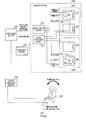
- FIG.2 is a block diagram illustrating the speaker system 100 shown in FIG.1 and peripheral components of the speaker system 100.
- the first R channel speaker 101 is arranged virtually in front of the driver's seat of the vehicle (for example, in/on a dashboard 200 ) in an initial state and outputs sound based on the in-phase signal of the R channel signal (hereinafter referred to as "in-phase signal (R)") from the sound source.
- in-phase signal (R) the in-phase signal
- the third L channel speaker 103 is arranged virtually in front of the front passenger seat next to the driver's seat (for example, in/on the dashboard 200 ) in an initial state, and outputs sound based on the in-phase signal of the L channel signal (hereinafter reffered to as "in-phase signal (L)”) from the same sound source as above.
- in-phase signal (L) in-phase signal
- this second reference plane d is parallel or virtually parallel to the longitudinal intermedian plane e of the vehicle, includes the listening position for the listener sitting in the front passenger seat (hereinafter reffered to as “the second listening position") and passes the middle point of the third and fourth L channel speakers 103 and 104. Further, as illustrated with the present embodiment, the second listening position is determined in advance around the head of the listener sitting in the front passenger seat.
- a pair of the first R channel speaker 101 and the second R channel speaker 102 composes a speaker unit SP1 of the driver' s seat side
- a pair of the third L channel speaker 103 and the fourth L channel speaker 104 composes a speaker unit SP2 of the front passenger seat side.
- the speaker units SP1 and SP2 are arranged in the driver's seat side and in the front passenger seat side of the dashboard 200 , respectively.
- the first R channel speaker 101 and the third L channel speaker 103 compose speakers for the listener (driver) in the driver's seat
- the second R channel speaker 102 and the fourth L channel speaker 104 compose speakers for the listener in the front passenger seat.
- a driving motor 113 that, while maintaining the defference of angle of elevation between the directivity axis of the first R channel speaker 101 and the directivity axis of the second R channel speaker 102, changes both the direction of the directivity axis of the first R channel speaker 101 and the direction of the directivity axis of the second R channel speaker 102 with respect to the plane where the speaker unit SP1 is installed.
- the driving motor 111 for changing the opening angle and the driving motor 112 for changing the above difference of angle of elevation are installed only in the first R channel speaker 101 , and, in the second R channel speaker 102 , driving motors for changing these opening angle and difference of angle of elevation are not installed. Further, the angle of elevation of the overall speaker unit SP1 can be changed by the driving motor 113.
- the speaker system 100 comprises a motor driver section 130 that drives the driving motors 111 and 121 for changing the opening angles, the drivingmotors 112 and 122 for changing the differences of angles of eleavations and the driving motors 113 and 123 for changing the angles of elevations of speaker units SP1 and SP2; and a sound processing section 141 that carries out signal processing of a 2-channel (i.e. L channel and R channel) signal from a sound input section 140, to which the sound source composed of the 2-channel signal is inputted, and generates the in-phase signal (R), the reverse phase signal (R), the in-phase signal (L) and the reverse phase signal (L) as mentioned above.
- a 2-channel i.e. L channel and R channel
- the in-phase signal (R), the reverse phase signal (R), the in-phase signal (L) and the reverse phase signal (L) that are generated by sound processing section 141, are outputted to the first R channel speaker 101, the second R channel speaker 102 , the third L channel speaker 103 and the fourth L channel speaker 104, respectively.
- the sound input section 140 is an input terminal that receives as input a sound source from audio devices such as CD players, DVD players, MD players, cassette decks, radios, television receivers and semiconductor memory audio devices or speech input apparatuses such as microphones. Further, the sound input section 140 may be an audio device or speech input apparatus itself.
- a controlling section 150 that controls, for example, the opening angle depending on the listening positions of a plurality of listeners and a position detecting section 160 that receives signals from contact switches 161 and 162 which detect the front-back position of a seat and the reclining angle of the seat and detects the location of the head of the seated listener.
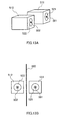
- the first R channel speaker 101 and the second R channel speaker 102 are mounted in the dashboard 200 of the driver's seat side such that the opening angle and the angle of elevation described below are formed.
- the third L channel speaker 103 and the fourth L channel speaker 104 are mounted in the dashboard 200 of the front passenger seat side such that the opening angle and the angle of elevation described below are formed.
- the first speaker unit SP1 and the second speaker unit SP2 are arranged in positions in plane symmetry with each other with respect to the longitudinal intermedian plane e including the longitudinal intermedian line of the vehicle.
- a method of arranging the first R channel speaker 101 and the second R channel speaker 102, and the third L channel speaker 103 and the fourth L channel speaker 104 on the dashboard 200 by slightly shifting these speakers right and left or back and forth from the front of the driver or the listener in the front passenger seat may be adopted.
- the first R channel speaker 101 , the second R channel speaker 102, the third L channel speaker 103 and the fourth L channel speaker 104 may not be directed toward the listener in the driver's seat (i.e. driver) and the listener in the front passenger seat.
- the second speaker unit SP2 is arranged in a position in symmetry with the first speaker unit SP1 with respect to the longitudinal intermedian plane e of the vehicle, the listener in the front passenger seat recognizes that there is a virtual image 106 of the fourth L channel speaker 104 in the front left outside the vehicle. Consequently, the listener sitting in the front passenger seat is able to listen to wide stereo sound, like the listener sitting in the driver's seat.
- the speaker system 100 comprises the speaker unit SP1 composed of the first R channel speaker 101 that radiates the in-phase R channel signal and the second R channel speaker 102 that radiates the reverse phase R channel signal, and the speaker unit SP2 composed of the third L channel speaker 103 that radiates the in-phase L channel signal and the fourth L channel speaker 104 that radiates the reverse phase L channel signal.
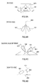
- the first R channel speaker 101 and the second R channel speaker 102 are in plane symmetry with respect to the first reference plane c including the current first listening position for the driver, and are arranged such that sound outputted from the first R channel speaker 101 is reflected by the side glass 210 and reaches the first listening position.
- the speaker unit SP1 and the listener P1 in the driver' s seat virtually face each other.
- the reference symbol " a " is assigned to the directivity axis of the first R channel speaker 101 that radiates sound based on the in-phase signal (R) and the reference symbol “b” is assigned to the directivity axis of the second R channel speaker 102 that radiates sound based on the reverse phase signal (R).
- the reference symbol "c" is assigned to the above-described first reference plane.
- the first reference plane c is a null plane in which sound based on the in-phase signal (R) and sound based on the reverse phase signal (R) cancel each other.
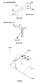
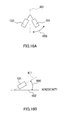
- FIG.4 is a schematic view illustrating the relationship between the direction of a speaker unit and the location of the listener, employing an example of the relationship between the positions of the speaker unit SP1 of the driver's seat side, the listener P1 in the driver's seat (i.e. driver) and the listener P2 in the front passenger seat.
- the speaker unit SP1 of the driver's seat side is installed on the dashboard 200 shown in FIG.1 .
- the reflecting plane A of FIG.4 is the side glass 210 of FIG.1 .
- This space inside the vehicle is represented by X and Y .
- the distance x3 from the speaker unit SP1 of the driver's seat side there are the distance x1 from the listener P1 in the driver's seat and the distance x2 from the listener P2 in the front passenger seat.
- the reference symbol " ⁇ " (see the dotted line) is assigned to the path through which the sound outputted from the first R channel speaker 101 composing the speaker unit SP1 (i.e. the in-phase signal (R)) is reflected by the reflecting plane A and reaches the listener P1 in the driver's seat, and the reference symbol " ⁇ " (see the dotted line) is assigned to the path through which the sound outputted from the second R channel speaker 102 (i.e. the reverse phase signal (R)) reaches directly the listener P2 in the front passenger seat.
- the listener P1 moves forward and is located at P1'.
- the listener P2 does not move.
- the right and left path lengths from the speakers to the listener P1 significantly change, thereby producing the difference between the right and left paths and, furthermore, the null plane moves right and left significantly.
- the angle of the line included in the null plane changes significantly (see the bold broken line in the figure to the bold chain line in the figure). Further, the directivity axes of the speakers are shifted from the center of the listener P1'.
- the difference is produced between the distance l 1 and the distance l 2 to P1' after movement.
- the symbol l 1 ' refers to the distance through which the sound outputted from the speaker unit SP1 is reflected by the reflecting plane 600 and reaches P1' from the location U1 after movement
- the symbol l 2 ' refers to the distance through which the sound outputted from the speaker unit SP2 reaches P1' from the location U2 directly.
- the relational equation of the difference ⁇ L between l 1 ' and l 2 ' is as follows.
- the distance x 4 from reflecting plane 620 of U2 which is equal to the distance l 4 through which sound is reflected by the reflecting plane 620 and reaches P2 from U2 and the distance l 2 connecting U1 and P2 directly, is represented by the following equation 10. Further, in the following equation 10, the symbol x 5 represents the distance between P2 and the reflecting plane 620, and the symbol x 6 represents the distance between P1 and the reflecting plane 620.
- step S32 by changing the opening angle in the speaker unit SP1 in step S32, reflected sound is adjusted such that quality of sound that is reflected and reaches the listener P1 improves.
- the method of adjustment is the same as in the case of the above step S13.
- Embodiment 1 An example has been described with Embodiment 1 where the shift in the null plane in which silence is generated in theory is adjusted using the "differences of angles of elevations" between speakers.
- the shift in the null plane is adjusted by “rotating” the entire speaker unit. Further, more precise adjustment is possible by adjusting the shift in the null plane by "rotating" the entire speaker unit.
- FIG.19 is a schematic view showing from above a speaker system 700 according to Embodiment 2 of the present invention and the interior of the vehicle mounting the speaker system 700
- FIG.20 is a block diagram showing the speaker system 700 shown in FIG.19 and configurations around the speaker system 700.
- the same parts as in FIG.1 and FIG.2 will be assigned the same reference numerals and repetition of description will be omitted.
- the speaker system 700 has: a motor driver section 730 that drives driving motors 111, 121, 714 and 724 for changing opening angles, driving motors 712 and 722 for changing rotation of the speaker units SP and driving motors 113 and 123 for changing angles of elevations of speaker units SP; and a sound processing section 141 that carries out signal processing of a 2-channel (i.e. L channel and R channel) signal from a sound input section 140 to which the sound source composed of the 2-channel signal is inputted and generates the in-phase signal (R), the reverse phase signal (R), the in-phase signal (L) and the reverse phase signal (L) as described above.
- a 2-channel i.e. L channel and R channel
- a controlling section 750 that controls, for example, opening angles according to listening positions of a plurality of listeners and a position detecting section 160 that detects the location of the head of the listener sitting in a seat by receiving signals from contact switches 161 and 162 which detect the front-back position of the seat and the reclining angle, are provided.
- the controlling section 750 is configured with a microprocessor, acquires head location information of the listener from the position detecting section 160 by executing a control program which will be described later in FIG.21 , outputs to the motor driver section 730 control commands for controlling opening angles, rotations and angles of elevations of the speakers 101 to 104 and the speaker units SP1 and SP2 according to the current first and second positions of listeners and outputs to the sound processing section 141 control signals for controlling the output volumes and phases of output sounds from the speakers 101 to 104.
- the motor driver section 730 precisely controls the amount of driving of an applicable driving motor according to the control commands and changes the current values of the opening angles, the rotations and the angles of elevations of the speakers 101 to 104 and the speaker units SP1 and SP2 to target values.
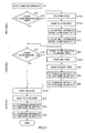
- the program starts following a change in the location of the listener P1 (step S1 ), whether or not the location of the listener P1 moved back and forth is decided in step S11.
- the movement in the location of the listener P1 is decided by acquiring head location information of the listener from the position detecting section 160 (see FIG.20 ). If the location of the listener P1 moves back and forth, the null plane is adjusted in step S12A.
- the controlling section 750 carries out an arithmetic operation for adjusting the null plane to place a null plane on the first listening position based on the amount of movement in the front-back position of the listener P1, converts the arithmetic operation result into control parameters and outputs the control parameters to the motor driver section 730.
- the motor driver section 730 drives an applicable driving motor (driving motor 712 in this description) to reach this target value based on the control commands from the controlling section 750.
- the null plane is adjusted by the "rotation" of the speaker unit SP2. Adjusting the null plane by the rotation is superior to the "differences of angles of elevations" adjustment for inclining the null plane using the line included in the null plane as a reference, in securing the required accuracy. Further, changing the rotation of the speaker unit SP2 provides an effect of more precisely adjusting the difference between the right and left sound volumes.
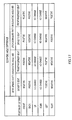
- the controlling section 750 stores as a table the relationship between the location of the listener P1 and the opening angle, at which reflected sound is heard the best for the listener P1, in the internal memory in advance and changes the opening angle referring to this table. Adjusting of the opening angles with the present embodiment is directed to adjusting opening angles of the first R channel speaker 101 and the second R channel speaker 102 shown in FIG.16 .
- the motor driver section 730 adjusts the reflected sound by the driving the driving motor 111 to a predetermined amount and changing the opening angles of the first R channel speaker 101 and the second R channel speaker 102.
- processing A Processings of the above step S11 to step S15 are referred to as "processing A”.
- processing B Processings of the above step S21 to step S26 are referred to as "processing B".
- the null plane is adjusted in step S31A.
- the method of adjustment uses the "rotation" as in the case of the above step S12A.
- step S32 by changing the opening angle in the speaker unit SP1 in step S32, reflected sound is adjusted such that quality of sound that is reflected and reaches the listener P1 improves.
- the method of adjustment is the same as in the case of the above step S13.
- steps S25 and S26 are carried out in steps S33 and S34, and this flow is finished.
- processing C Processings of the above step S31 to step S34 are referred to as "processing C".
- the order to execute the above processings A, B and C can be switched. Further, similar to Embodiment 1, the timing to execute this flow is arbitrary, and, for example, the program may be started if the location of the listener changes more than a predetermined distance and may be executed at all time and adjustment may be carried out in real time processing.
- the speaker system 700 has a driving motor 712 for rotating the first speaker unit SP1 and a driving motor 722 for rotating the second speaker unit SP2, so that, similar to Embodiment 1, even if the first and the second listening positions move back and forth, right and left or up and down, it is possible to automatically adjust the directions and outputs sounds of the speakers 101 to 104 and realize a speaker system that is able to provide to a plurality of listeners at the same time a listening environment which does not give a sense of discomfort.
- speaker system is used with the above embodiments for ease of description, other terms are certainly possible, including, for example, “audio system,” “audio playback system,” “speaker apparatus mounted in the vehicle” and “audio devices mounted in the vehicle.”
- each circuit section forming the above speaker system for example, the type, number and connecting method of signal processing sections and position detecting sections are not limited to the above described embodiment.
Landscapes
- Health & Medical Sciences (AREA)
- Otolaryngology (AREA)
- Physics & Mathematics (AREA)
- Engineering & Computer Science (AREA)
- Acoustics & Sound (AREA)
- Signal Processing (AREA)
- General Health & Medical Sciences (AREA)
- Fittings On The Vehicle Exterior For Carrying Loads, And Devices For Holding Or Mounting Articles (AREA)
- Stereophonic System (AREA)
- Stereophonic Arrangements (AREA)
- Obtaining Desirable Characteristics In Audible-Bandwidth Transducers (AREA)
Applications Claiming Priority (2)
| Application Number | Priority Date | Filing Date | Title |
|---|---|---|---|
| JP2006194812A JP4989934B2 (ja) | 2006-07-14 | 2006-07-14 | スピーカシステム |
| PCT/JP2007/060827 WO2008007502A1 (fr) | 2006-07-14 | 2007-05-28 | Système de haut-parleurs |
Publications (3)
| Publication Number | Publication Date |
|---|---|
| EP2043390A1 true EP2043390A1 (fr) | 2009-04-01 |
| EP2043390A4 EP2043390A4 (fr) | 2011-04-27 |
| EP2043390B1 EP2043390B1 (fr) | 2015-09-30 |
Family
ID=38923071
Family Applications (1)
| Application Number | Title | Priority Date | Filing Date |
|---|---|---|---|
| EP07744261.4A Ceased EP2043390B1 (fr) | 2006-07-14 | 2007-05-28 | Systeme de haut-parleurs |
Country Status (5)
| Country | Link |
|---|---|
| US (1) | US8315401B2 (fr) |
| EP (1) | EP2043390B1 (fr) |
| JP (1) | JP4989934B2 (fr) |
| CN (1) | CN101491118B (fr) |
| WO (1) | WO2008007502A1 (fr) |
Cited By (3)
| Publication number | Priority date | Publication date | Assignee | Title |
|---|---|---|---|---|
| WO2009154902A1 (fr) * | 2008-06-16 | 2009-12-23 | Sony Ericsson Mobile Communications Ab | Configuration de système audiovisuel automatisée |
| EP2731360A3 (fr) * | 2012-11-09 | 2017-01-04 | Harman International Industries, Inc. | Système d'amélioration audio automatique |
| GB2589950A (en) * | 2019-10-28 | 2021-06-16 | Fujitsu Client Computing Ltd | Information processing system, information processing apparatus, and program |
Families Citing this family (29)
| Publication number | Priority date | Publication date | Assignee | Title |
|---|---|---|---|---|
| WO2007070660A2 (fr) | 2005-12-13 | 2007-06-21 | President And Fellows Of Harvard College | Echafaudages pour transplantation cellulaire |
| JP2009260628A (ja) * | 2008-04-16 | 2009-11-05 | Sony Corp | オーディオ再生装置 |
| EP2181895A3 (fr) | 2008-10-29 | 2010-08-25 | Bang&Olufsen A/S | Agencement de haut-parleur coulissant asymétrique |
| JP2010206451A (ja) * | 2009-03-03 | 2010-09-16 | Panasonic Corp | カメラ付きスピーカ、信号処理装置、およびavシステム |
| JP2010228564A (ja) * | 2009-03-26 | 2010-10-14 | Yamaha Corp | 自動車 |
| JP2011205487A (ja) * | 2010-03-26 | 2011-10-13 | Panasonic Corp | 指向性音響システム |
| KR101717787B1 (ko) * | 2010-04-29 | 2017-03-17 | 엘지전자 주식회사 | 디스플레이장치 및 그의 음성신호 출력 방법 |
| JP5682244B2 (ja) * | 2010-11-09 | 2015-03-11 | ソニー株式会社 | スピーカーシステム |
| CN102006544B (zh) * | 2010-11-16 | 2012-07-25 | 哈尔滨工业大学 | 长空间内强指向性声源系统的实现方法 |
| KR101619546B1 (ko) * | 2010-11-24 | 2016-05-10 | 현대자동차주식회사 | 팝업트위터 스피커 |
| JP2013034233A (ja) * | 2012-10-10 | 2013-02-14 | Nippon Telegr & Teleph Corp <Ntt> | 音響再生装置及び音響再生方法 |
| US9088842B2 (en) | 2013-03-13 | 2015-07-21 | Bose Corporation | Grille for electroacoustic transducer |
| CN104144370A (zh) * | 2013-05-06 | 2014-11-12 | 象水国际股份有限公司 | 可追踪目标的扬声装置及其声音输出方法 |
| US9327628B2 (en) | 2013-05-31 | 2016-05-03 | Bose Corporation | Automobile headrest |
| US9699537B2 (en) | 2014-01-14 | 2017-07-04 | Bose Corporation | Vehicle headrest with speakers |
| US9866986B2 (en) | 2014-01-24 | 2018-01-09 | Sony Corporation | Audio speaker system with virtual music performance |
| US9544679B2 (en) * | 2014-12-08 | 2017-01-10 | Harman International Industries, Inc. | Adjusting speakers using facial recognition |
| US9924291B2 (en) | 2016-02-16 | 2018-03-20 | Sony Corporation | Distributed wireless speaker system |
| US9826330B2 (en) * | 2016-03-14 | 2017-11-21 | Sony Corporation | Gimbal-mounted linear ultrasonic speaker assembly |
| US9794724B1 (en) | 2016-07-20 | 2017-10-17 | Sony Corporation | Ultrasonic speaker assembly using variable carrier frequency to establish third dimension sound locating |
| US10089063B2 (en) * | 2016-08-10 | 2018-10-02 | Qualcomm Incorporated | Multimedia device for processing spatialized audio based on movement |
| US10237644B1 (en) * | 2016-09-23 | 2019-03-19 | Apple Inc. | Enhancing a listening experience by adjusting physical attributes of an audio playback system based on detected environmental attributes of the system's environment |
| CN109104686B (zh) * | 2017-09-30 | 2019-12-20 | 惠州市德赛西威汽车电子股份有限公司 | 一种汽车音响立体声扩展方法 |
| US11575991B2 (en) * | 2018-10-24 | 2023-02-07 | Clean Energy Labs, Llc | Stereophonic loudspeaker system and method of use thereof |
| CN111252006A (zh) * | 2018-11-30 | 2020-06-09 | 长城汽车股份有限公司 | 中置扬声器的指向性调整方法及装置 |
| CN110072172B (zh) * | 2019-04-25 | 2020-10-16 | 广州小鹏汽车科技有限公司 | 一种音频信号的输出方法、系统、电子设备及可读介质 |
| WO2021000086A1 (fr) * | 2019-06-29 | 2021-01-07 | 瑞声声学科技(深圳)有限公司 | Système de champ sonore indépendant, embarqué, à micro-haut-parleurs, et système de commande |
| US11443737B2 (en) | 2020-01-14 | 2022-09-13 | Sony Corporation | Audio video translation into multiple languages for respective listeners |
| CN113115199B (zh) * | 2021-03-12 | 2022-05-24 | 华南理工大学 | 一种适应听音中心位的车载声重放信号延时方法 |
Family Cites Families (17)
| Publication number | Priority date | Publication date | Assignee | Title |
|---|---|---|---|---|
| JPS6326197A (ja) * | 1986-07-18 | 1988-02-03 | Nippon Telegr & Teleph Corp <Ntt> | ステレオ再生装置の調整方法 |
| US4764960A (en) * | 1986-07-18 | 1988-08-16 | Nippon Telegraph And Telephone Corporation | Stereo reproduction system |
| JPH0377500A (ja) * | 1989-08-19 | 1991-04-03 | Sanyo Electric Co Ltd | 音場補正装置 |
| JP2841994B2 (ja) * | 1992-01-09 | 1998-12-24 | 日産自動車株式会社 | アクチュエータ制御装置 |
| JP2901431B2 (ja) * | 1992-08-27 | 1999-06-07 | 株式会社ケンウッド | 車室内音響再生装置 |
| JPH06153290A (ja) | 1992-11-02 | 1994-05-31 | Matsushita Electric Ind Co Ltd | スピーカ装置 |
| JP3077500B2 (ja) | 1994-03-28 | 2000-08-14 | 日産自動車株式会社 | 車両用灯具のレンズ |
| US5809150A (en) * | 1995-06-28 | 1998-09-15 | Eberbach; Steven J. | Surround sound loudspeaker system |
| JP3826976B2 (ja) * | 1997-08-27 | 2006-09-27 | 富士通テン株式会社 | 車載用音響再生装置 |
| JP2001298787A (ja) * | 2000-04-14 | 2001-10-26 | Mitsubishi Electric Corp | スピーカ装置 |
| JP2003048490A (ja) | 2001-08-07 | 2003-02-18 | Mechanical Research:Kk | 車載用スピーカ装置 |
| US20040105550A1 (en) * | 2002-12-03 | 2004-06-03 | Aylward J. Richard | Directional electroacoustical transducing |
| JP2004289341A (ja) | 2003-03-20 | 2004-10-14 | Niro1.Com Inc | 車載用スピーカ装置 |
| DE10324640B3 (de) * | 2003-05-28 | 2004-05-27 | Reitter & Schefenacker Sound Gmbh | Ausfahrbarer Lautsprecher |
| JP2006134287A (ja) * | 2004-10-07 | 2006-05-25 | Matsushita Electric Ind Co Ltd | 電子装置 |
| JP2006194812A (ja) | 2005-01-17 | 2006-07-27 | Shimadzu Corp | 分光蛍光光度計 |
| US8942395B2 (en) * | 2007-01-17 | 2015-01-27 | Harman International Industries, Incorporated | Pointing element enhanced speaker system |
-
2006
- 2006-07-14 JP JP2006194812A patent/JP4989934B2/ja not_active Expired - Fee Related
-
2007
- 2007-05-28 EP EP07744261.4A patent/EP2043390B1/fr not_active Ceased
- 2007-05-28 US US12/373,631 patent/US8315401B2/en not_active Expired - Fee Related
- 2007-05-28 WO PCT/JP2007/060827 patent/WO2008007502A1/fr not_active Ceased
- 2007-05-28 CN CN200780026702.5A patent/CN101491118B/zh not_active Expired - Fee Related
Cited By (4)
| Publication number | Priority date | Publication date | Assignee | Title |
|---|---|---|---|---|
| WO2009154902A1 (fr) * | 2008-06-16 | 2009-12-23 | Sony Ericsson Mobile Communications Ab | Configuration de système audiovisuel automatisée |
| EP2731360A3 (fr) * | 2012-11-09 | 2017-01-04 | Harman International Industries, Inc. | Système d'amélioration audio automatique |
| US9591405B2 (en) | 2012-11-09 | 2017-03-07 | Harman International Industries, Incorporated | Automatic audio enhancement system |
| GB2589950A (en) * | 2019-10-28 | 2021-06-16 | Fujitsu Client Computing Ltd | Information processing system, information processing apparatus, and program |
Also Published As
| Publication number | Publication date |
|---|---|
| CN101491118B (zh) | 2011-07-27 |
| EP2043390A4 (fr) | 2011-04-27 |
| JP4989934B2 (ja) | 2012-08-01 |
| US20100272271A1 (en) | 2010-10-28 |
| US8315401B2 (en) | 2012-11-20 |
| CN101491118A (zh) | 2009-07-22 |
| WO2008007502A1 (fr) | 2008-01-17 |
| EP2043390B1 (fr) | 2015-09-30 |
| JP2008022495A (ja) | 2008-01-31 |
Similar Documents
| Publication | Publication Date | Title |
|---|---|---|
| EP2043390B1 (fr) | Systeme de haut-parleurs | |
| US8170246B2 (en) | Apparatus and method for reproducing surround wave field using wave field synthesis | |
| US8045736B2 (en) | Sound field reproduction system | |
| JP5184741B2 (ja) | 車両マルチチャネルオーディオシステムにおける中央チャネル情報の再生 | |
| JP6286583B2 (ja) | ラウドスピーカシステム | |
| KR100799783B1 (ko) | 차량용 스피커 어레이 | |
| US9578438B2 (en) | Apparatus and method for driving loudspeakers of a sound system in a vehicle | |
| US20070268415A1 (en) | Vehicle mounted display apparatus and sound controlling method | |
| JP3922275B2 (ja) | 音声再生装置及び音声再生装置の音声ビーム反射位置補正方法 | |
| CN111480346A (zh) | 车辆用音响系统 | |
| JP2023126870A (ja) | 車両向けの空間インフォテインメントレンダリングシステム | |
| US20090052700A1 (en) | Surround-sound system | |
| JP2009147815A (ja) | 音響空間制御装置及び音響空間制御方法 | |
| JP2007312081A (ja) | オーディオシステム | |
| JP2006188181A (ja) | 車載用マルチメディア装置 | |
| JP2007324907A (ja) | スピーカシステム | |
| JP2008227942A (ja) | コンテンツ再生装置及びコンテンツ再生方法 | |
| EP4412246B1 (fr) | Dispositif de traitement de son, système de son et procédé de traitement de son | |
| JP2021024481A (ja) | 電子ミラーシステム、電子ミラー装置および情報出力方法 | |
| JP2007019940A (ja) | 音場制御装置 | |
| JP2002315099A (ja) | 車載用オーディオ/ビジュアルシステム | |
| EP1509064A2 (fr) | Procédé de montage et de commande pour haut-parleurs. | |
| JP2007043348A (ja) | 車載用音響制御装置および方法 | |
| JP2006050094A (ja) | 映像音響再生システム | |
| JP2007310236A (ja) | アプリケーション制御装置 |
Legal Events
| Date | Code | Title | Description |
|---|---|---|---|
| PUAI | Public reference made under article 153(3) epc to a published international application that has entered the european phase |
Free format text: ORIGINAL CODE: 0009012 |
|
| 17P | Request for examination filed |
Effective date: 20090114 |
|
| AK | Designated contracting states |
Kind code of ref document: A1 Designated state(s): AT BE BG CH CY CZ DE DK EE ES FI FR GB GR HU IE IS IT LI LT LU LV MC MT NL PL PT RO SE SI SK TR |
|
| AX | Request for extension of the european patent |
Extension state: AL BA HR MK RS |
|
| DAX | Request for extension of the european patent (deleted) | ||
| RBV | Designated contracting states (corrected) |
Designated state(s): DE FR GB |
|
| A4 | Supplementary search report drawn up and despatched |
Effective date: 20110325 |
|
| RAP1 | Party data changed (applicant data changed or rights of an application transferred) |
Owner name: PANASONIC INTELLECTUAL PROPERTY MANAGEMENT CO., LT |
|
| RAP1 | Party data changed (applicant data changed or rights of an application transferred) |
Owner name: PANASONIC INTELLECTUAL PROPERTY MANAGEMENT CO., LT |
|
| GRAP | Despatch of communication of intention to grant a patent |
Free format text: ORIGINAL CODE: EPIDOSNIGR1 |
|
| INTG | Intention to grant announced |
Effective date: 20150420 |
|
| GRAS | Grant fee paid |
Free format text: ORIGINAL CODE: EPIDOSNIGR3 |
|
| GRAA | (expected) grant |
Free format text: ORIGINAL CODE: 0009210 |
|
| AK | Designated contracting states |
Kind code of ref document: B1 Designated state(s): DE FR GB |
|
| REG | Reference to a national code |
Ref country code: GB Ref legal event code: FG4D |
|
| REG | Reference to a national code |
Ref country code: DE Ref legal event code: R096 Ref document number: 602007043316 Country of ref document: DE |
|
| REG | Reference to a national code |
Ref country code: FR Ref legal event code: PLFP Year of fee payment: 10 |
|
| REG | Reference to a national code |
Ref country code: DE Ref legal event code: R097 Ref document number: 602007043316 Country of ref document: DE |
|
| PLBE | No opposition filed within time limit |
Free format text: ORIGINAL CODE: 0009261 |
|
| STAA | Information on the status of an ep patent application or granted ep patent |
Free format text: STATUS: NO OPPOSITION FILED WITHIN TIME LIMIT |
|
| 26N | No opposition filed |
Effective date: 20160701 |
|
| REG | Reference to a national code |
Ref country code: FR Ref legal event code: PLFP Year of fee payment: 11 |
|
| REG | Reference to a national code |
Ref country code: FR Ref legal event code: PLFP Year of fee payment: 12 |
|
| REG | Reference to a national code |
Ref country code: DE Ref legal event code: R084 Ref document number: 602007043316 Country of ref document: DE |
|
| PGFP | Annual fee paid to national office [announced via postgrant information from national office to epo] |
Ref country code: FR Payment date: 20200522 Year of fee payment: 14 Ref country code: DE Payment date: 20200520 Year of fee payment: 14 |
|
| PGFP | Annual fee paid to national office [announced via postgrant information from national office to epo] |
Ref country code: GB Payment date: 20200527 Year of fee payment: 14 |
|
| REG | Reference to a national code |
Ref country code: DE Ref legal event code: R119 Ref document number: 602007043316 Country of ref document: DE |
|
| GBPC | Gb: european patent ceased through non-payment of renewal fee |
Effective date: 20210528 |
|
| PG25 | Lapsed in a contracting state [announced via postgrant information from national office to epo] |
Ref country code: GB Free format text: LAPSE BECAUSE OF NON-PAYMENT OF DUE FEES Effective date: 20210528 Ref country code: DE Free format text: LAPSE BECAUSE OF NON-PAYMENT OF DUE FEES Effective date: 20211201 |
|
| PG25 | Lapsed in a contracting state [announced via postgrant information from national office to epo] |
Ref country code: FR Free format text: LAPSE BECAUSE OF NON-PAYMENT OF DUE FEES Effective date: 20210531 |