EP2043867B1 - Tintenstrahldruckkopf mit gesteuerter entleerung - Google Patents
Tintenstrahldruckkopf mit gesteuerter entleerung Download PDFInfo
- Publication number
- EP2043867B1 EP2043867B1 EP06760924A EP06760924A EP2043867B1 EP 2043867 B1 EP2043867 B1 EP 2043867B1 EP 06760924 A EP06760924 A EP 06760924A EP 06760924 A EP06760924 A EP 06760924A EP 2043867 B1 EP2043867 B1 EP 2043867B1
- Authority
- EP
- European Patent Office
- Prior art keywords
- ink
- printhead
- manifold
- pump
- upstream
- Prior art date
- Legal status (The legal status is an assumption and is not a legal conclusion. Google has not performed a legal analysis and makes no representation as to the accuracy of the status listed.)
- Ceased
Links
- 238000011144 upstream manufacturing Methods 0.000 claims description 49
- 239000012530 fluid Substances 0.000 claims description 38
- 238000004891 communication Methods 0.000 claims description 13
- 230000002441 reversible effect Effects 0.000 claims description 7
- 238000005086 pumping Methods 0.000 claims description 4
- 230000003247 decreasing effect Effects 0.000 abstract 1
- 239000000976 ink Substances 0.000 description 259
- 229920000106 Liquid crystal polymer Polymers 0.000 description 25
- 239000004977 Liquid-crystal polymers (LCPs) Substances 0.000 description 25
- 239000007789 gas Substances 0.000 description 20
- 238000007789 sealing Methods 0.000 description 20
- 229920000642 polymer Polymers 0.000 description 13
- 239000012790 adhesive layer Substances 0.000 description 11
- 238000012423 maintenance Methods 0.000 description 10
- 238000002156 mixing Methods 0.000 description 10
- 238000010943 off-gassing Methods 0.000 description 10
- 230000002572 peristaltic effect Effects 0.000 description 10
- 238000010926 purge Methods 0.000 description 10
- 238000000034 method Methods 0.000 description 9
- 238000000465 moulding Methods 0.000 description 9
- 238000007639 printing Methods 0.000 description 7
- 238000003860 storage Methods 0.000 description 7
- QLCTXEMDCZGPCG-UHFFFAOYSA-N 1,2-dichloro-4-(3,5-dichlorophenyl)benzene Chemical compound ClC1=CC(Cl)=CC(C=2C=C(Cl)C(Cl)=CC=2)=C1 QLCTXEMDCZGPCG-UHFFFAOYSA-N 0.000 description 6
- 238000012937 correction Methods 0.000 description 6
- 238000013461 design Methods 0.000 description 6
- XUIMIQQOPSSXEZ-UHFFFAOYSA-N Silicon Chemical compound [Si] XUIMIQQOPSSXEZ-UHFFFAOYSA-N 0.000 description 5
- 230000007246 mechanism Effects 0.000 description 5
- 229910052710 silicon Inorganic materials 0.000 description 5
- 239000010703 silicon Substances 0.000 description 5
- 238000004140 cleaning Methods 0.000 description 4
- 239000003086 colorant Substances 0.000 description 4
- 238000006073 displacement reaction Methods 0.000 description 4
- 239000006260 foam Substances 0.000 description 4
- 230000036571 hydration Effects 0.000 description 4
- 238000006703 hydration reaction Methods 0.000 description 4
- 239000002313 adhesive film Substances 0.000 description 3
- 230000001627 detrimental effect Effects 0.000 description 3
- 238000007641 inkjet printing Methods 0.000 description 3
- 238000002844 melting Methods 0.000 description 3
- 230000008018 melting Effects 0.000 description 3
- 238000003825 pressing Methods 0.000 description 3
- 230000037452 priming Effects 0.000 description 3
- IJGRMHOSHXDMSA-UHFFFAOYSA-N Atomic nitrogen Chemical compound N#N IJGRMHOSHXDMSA-UHFFFAOYSA-N 0.000 description 2
- 235000013290 Sagittaria latifolia Nutrition 0.000 description 2
- PPBRXRYQALVLMV-UHFFFAOYSA-N Styrene Chemical compound C=CC1=CC=CC=C1 PPBRXRYQALVLMV-UHFFFAOYSA-N 0.000 description 2
- 239000000853 adhesive Substances 0.000 description 2
- 230000001070 adhesive effect Effects 0.000 description 2
- 235000015246 common arrowhead Nutrition 0.000 description 2
- 239000000356 contaminant Substances 0.000 description 2
- 238000011109 contamination Methods 0.000 description 2
- 238000001816 cooling Methods 0.000 description 2
- 239000000428 dust Substances 0.000 description 2
- 238000010304 firing Methods 0.000 description 2
- 230000002706 hydrostatic effect Effects 0.000 description 2
- 238000005304 joining Methods 0.000 description 2
- 239000007788 liquid Substances 0.000 description 2
- 239000000463 material Substances 0.000 description 2
- 238000012986 modification Methods 0.000 description 2
- 230000004048 modification Effects 0.000 description 2
- 239000011295 pitch Substances 0.000 description 2
- 239000005020 polyethylene terephthalate Substances 0.000 description 2
- 229920000139 polyethylene terephthalate Polymers 0.000 description 2
- 238000007665 sagging Methods 0.000 description 2
- 238000012546 transfer Methods 0.000 description 2
- 238000006424 Flood reaction Methods 0.000 description 1
- 239000004677 Nylon Substances 0.000 description 1
- 239000004743 Polypropylene Substances 0.000 description 1
- 239000011324 bead Substances 0.000 description 1
- 239000003990 capacitor Substances 0.000 description 1
- 230000008859 change Effects 0.000 description 1
- 239000011248 coating agent Substances 0.000 description 1
- 238000000576 coating method Methods 0.000 description 1
- 230000001419 dependent effect Effects 0.000 description 1
- 238000000151 deposition Methods 0.000 description 1
- 238000009792 diffusion process Methods 0.000 description 1
- 238000001035 drying Methods 0.000 description 1
- 230000009977 dual effect Effects 0.000 description 1
- 238000005516 engineering process Methods 0.000 description 1
- 238000005530 etching Methods 0.000 description 1
- 238000011049 filling Methods 0.000 description 1
- 238000010438 heat treatment Methods 0.000 description 1
- 235000003642 hunger Nutrition 0.000 description 1
- 238000003384 imaging method Methods 0.000 description 1
- 230000007774 longterm Effects 0.000 description 1
- 238000004519 manufacturing process Methods 0.000 description 1
- 229910052757 nitrogen Inorganic materials 0.000 description 1
- 229920001778 nylon Polymers 0.000 description 1
- 230000003204 osmotic effect Effects 0.000 description 1
- 239000013618 particulate matter Substances 0.000 description 1
- 230000002085 persistent effect Effects 0.000 description 1
- 239000004033 plastic Substances 0.000 description 1
- 229920003023 plastic Polymers 0.000 description 1
- 229920002492 poly(sulfone) Polymers 0.000 description 1
- 239000004417 polycarbonate Substances 0.000 description 1
- 229920000515 polycarbonate Polymers 0.000 description 1
- -1 polypropylene Polymers 0.000 description 1
- 229920001155 polypropylene Polymers 0.000 description 1
- 230000007420 reactivation Effects 0.000 description 1
- 230000000717 retained effect Effects 0.000 description 1
- 239000004065 semiconductor Substances 0.000 description 1
- 239000002904 solvent Substances 0.000 description 1
- 230000037351 starvation Effects 0.000 description 1
- 229920001169 thermoplastic Polymers 0.000 description 1
- 229920001187 thermosetting polymer Polymers 0.000 description 1
- 239000004416 thermosoftening plastic Substances 0.000 description 1
- 238000013022 venting Methods 0.000 description 1
- 235000001892 vitamin D2 Nutrition 0.000 description 1
- 239000002699 waste material Substances 0.000 description 1
Images






Classifications
-
- B—PERFORMING OPERATIONS; TRANSPORTING
- B41—PRINTING; LINING MACHINES; TYPEWRITERS; STAMPS
- B41J—TYPEWRITERS; SELECTIVE PRINTING MECHANISMS, i.e. MECHANISMS PRINTING OTHERWISE THAN FROM A FORME; CORRECTION OF TYPOGRAPHICAL ERRORS
- B41J2/00—Typewriters or selective printing mechanisms characterised by the printing or marking process for which they are designed
- B41J2/005—Typewriters or selective printing mechanisms characterised by the printing or marking process for which they are designed characterised by bringing liquid or particles selectively into contact with a printing material
- B41J2/01—Ink jet
- B41J2/17—Ink jet characterised by ink handling
- B41J2/1707—Conditioning of the inside of ink supply circuits, e.g. flushing during start-up or shut-down
-
- B—PERFORMING OPERATIONS; TRANSPORTING
- B41—PRINTING; LINING MACHINES; TYPEWRITERS; STAMPS
- B41J—TYPEWRITERS; SELECTIVE PRINTING MECHANISMS, i.e. MECHANISMS PRINTING OTHERWISE THAN FROM A FORME; CORRECTION OF TYPOGRAPHICAL ERRORS
- B41J2/00—Typewriters or selective printing mechanisms characterised by the printing or marking process for which they are designed
- B41J2/005—Typewriters or selective printing mechanisms characterised by the printing or marking process for which they are designed characterised by bringing liquid or particles selectively into contact with a printing material
- B41J2/01—Ink jet
- B41J2/135—Nozzles
- B41J2/145—Arrangement thereof
- B41J2/155—Arrangement thereof for line printing
-
- B—PERFORMING OPERATIONS; TRANSPORTING
- B41—PRINTING; LINING MACHINES; TYPEWRITERS; STAMPS
- B41J—TYPEWRITERS; SELECTIVE PRINTING MECHANISMS, i.e. MECHANISMS PRINTING OTHERWISE THAN FROM A FORME; CORRECTION OF TYPOGRAPHICAL ERRORS
- B41J2/00—Typewriters or selective printing mechanisms characterised by the printing or marking process for which they are designed
- B41J2/005—Typewriters or selective printing mechanisms characterised by the printing or marking process for which they are designed characterised by bringing liquid or particles selectively into contact with a printing material
- B41J2/01—Ink jet
- B41J2/135—Nozzles
- B41J2/165—Prevention or detection of nozzle clogging, e.g. cleaning, capping or moistening for nozzles
- B41J2/16517—Cleaning of print head nozzles
- B41J2/1652—Cleaning of print head nozzles by driving a fluid through the nozzles to the outside thereof, e.g. by applying pressure to the inside or vacuum at the outside of the print head
- B41J2/16526—Cleaning of print head nozzles by driving a fluid through the nozzles to the outside thereof, e.g. by applying pressure to the inside or vacuum at the outside of the print head by applying pressure only
-
- B—PERFORMING OPERATIONS; TRANSPORTING
- B41—PRINTING; LINING MACHINES; TYPEWRITERS; STAMPS
- B41J—TYPEWRITERS; SELECTIVE PRINTING MECHANISMS, i.e. MECHANISMS PRINTING OTHERWISE THAN FROM A FORME; CORRECTION OF TYPOGRAPHICAL ERRORS
- B41J2/00—Typewriters or selective printing mechanisms characterised by the printing or marking process for which they are designed
- B41J2/005—Typewriters or selective printing mechanisms characterised by the printing or marking process for which they are designed characterised by bringing liquid or particles selectively into contact with a printing material
- B41J2/01—Ink jet
- B41J2/17—Ink jet characterised by ink handling
- B41J2/175—Ink supply systems ; Circuit parts therefor
-
- B—PERFORMING OPERATIONS; TRANSPORTING
- B41—PRINTING; LINING MACHINES; TYPEWRITERS; STAMPS
- B41J—TYPEWRITERS; SELECTIVE PRINTING MECHANISMS, i.e. MECHANISMS PRINTING OTHERWISE THAN FROM A FORME; CORRECTION OF TYPOGRAPHICAL ERRORS
- B41J2/00—Typewriters or selective printing mechanisms characterised by the printing or marking process for which they are designed
- B41J2/005—Typewriters or selective printing mechanisms characterised by the printing or marking process for which they are designed characterised by bringing liquid or particles selectively into contact with a printing material
- B41J2/01—Ink jet
- B41J2/17—Ink jet characterised by ink handling
- B41J2/175—Ink supply systems ; Circuit parts therefor
- B41J2/17503—Ink cartridges
- B41J2/17506—Refilling of the cartridge
- B41J2/17509—Whilst mounted in the printer
-
- B—PERFORMING OPERATIONS; TRANSPORTING
- B41—PRINTING; LINING MACHINES; TYPEWRITERS; STAMPS
- B41J—TYPEWRITERS; SELECTIVE PRINTING MECHANISMS, i.e. MECHANISMS PRINTING OTHERWISE THAN FROM A FORME; CORRECTION OF TYPOGRAPHICAL ERRORS
- B41J2/00—Typewriters or selective printing mechanisms characterised by the printing or marking process for which they are designed
- B41J2/005—Typewriters or selective printing mechanisms characterised by the printing or marking process for which they are designed characterised by bringing liquid or particles selectively into contact with a printing material
- B41J2/01—Ink jet
- B41J2/17—Ink jet characterised by ink handling
- B41J2/175—Ink supply systems ; Circuit parts therefor
- B41J2/17596—Ink pumps, ink valves
-
- B—PERFORMING OPERATIONS; TRANSPORTING
- B41—PRINTING; LINING MACHINES; TYPEWRITERS; STAMPS
- B41J—TYPEWRITERS; SELECTIVE PRINTING MECHANISMS, i.e. MECHANISMS PRINTING OTHERWISE THAN FROM A FORME; CORRECTION OF TYPOGRAPHICAL ERRORS
- B41J29/00—Details of, or accessories for, typewriters or selective printing mechanisms not otherwise provided for
- B41J29/08—Sound-deadening, or shock-absorbing stands, supports, cases or pads separate from machines
-
- B—PERFORMING OPERATIONS; TRANSPORTING
- B41—PRINTING; LINING MACHINES; TYPEWRITERS; STAMPS
- B41J—TYPEWRITERS; SELECTIVE PRINTING MECHANISMS, i.e. MECHANISMS PRINTING OTHERWISE THAN FROM A FORME; CORRECTION OF TYPOGRAPHICAL ERRORS
- B41J2/00—Typewriters or selective printing mechanisms characterised by the printing or marking process for which they are designed
- B41J2/005—Typewriters or selective printing mechanisms characterised by the printing or marking process for which they are designed characterised by bringing liquid or particles selectively into contact with a printing material
- B41J2/01—Ink jet
- B41J2/135—Nozzles
- B41J2/14—Structure thereof only for on-demand ink jet heads
- B41J2002/14419—Manifold
-
- B—PERFORMING OPERATIONS; TRANSPORTING
- B41—PRINTING; LINING MACHINES; TYPEWRITERS; STAMPS
- B41J—TYPEWRITERS; SELECTIVE PRINTING MECHANISMS, i.e. MECHANISMS PRINTING OTHERWISE THAN FROM A FORME; CORRECTION OF TYPOGRAPHICAL ERRORS
- B41J2/00—Typewriters or selective printing mechanisms characterised by the printing or marking process for which they are designed
- B41J2/005—Typewriters or selective printing mechanisms characterised by the printing or marking process for which they are designed characterised by bringing liquid or particles selectively into contact with a printing material
- B41J2/01—Ink jet
- B41J2/135—Nozzles
- B41J2/14—Structure thereof only for on-demand ink jet heads
- B41J2002/14459—Matrix arrangement of the pressure chambers
-
- B—PERFORMING OPERATIONS; TRANSPORTING
- B41—PRINTING; LINING MACHINES; TYPEWRITERS; STAMPS
- B41J—TYPEWRITERS; SELECTIVE PRINTING MECHANISMS, i.e. MECHANISMS PRINTING OTHERWISE THAN FROM A FORME; CORRECTION OF TYPOGRAPHICAL ERRORS
- B41J2202/00—Embodiments of or processes related to ink-jet or thermal heads
- B41J2202/01—Embodiments of or processes related to ink-jet heads
- B41J2202/19—Assembling head units
-
- B—PERFORMING OPERATIONS; TRANSPORTING
- B41—PRINTING; LINING MACHINES; TYPEWRITERS; STAMPS
- B41J—TYPEWRITERS; SELECTIVE PRINTING MECHANISMS, i.e. MECHANISMS PRINTING OTHERWISE THAN FROM A FORME; CORRECTION OF TYPOGRAPHICAL ERRORS
- B41J2202/00—Embodiments of or processes related to ink-jet or thermal heads
- B41J2202/01—Embodiments of or processes related to ink-jet heads
- B41J2202/20—Modules
Definitions
- the present invention relates to the field of printing and in particular inkjet printing.
- Inkjet printing is a popular and versatile form of print imaging.
- the Assignee has developed printers that eject ink through MEMS printhead IC's.
- These printhead IC's integrated circuits are formed using lithographic etching and deposition techniques used for semiconductor fabrication.
- micro-scale nozzle structures in MEMS printhead IC's allow a high nozzle density (nozzles per unit of IC surface area), high print resolutions, low power consumption, self cooling operation and therefore high print speeds.
- Such printheads are described in detail in US Patent 6746105 (Docket No. MJ40US), filed June 4, 2002 and US Patent Application No. 10/728804 (Docket No. MTB01US), filed 8 December 2003 to the present Assignee.
- the small nozzle structures and high nozzle densities can create difficulties with nozzle clogging, de-priming, nozzle drying (decap), color mixing, nozzle flooding, bubble contamination in the ink stream and so on.
- Each of these issues can produce artifacts that are detrimental to the print quality.
- the component parts of the printer are designed to minimize the risk that these problems will occur. The optimum situation would be printer components whose inherent function is able to preclude these problem issues from arising. In reality, the many different types of operating conditions, mishaps, unduly rough handling during transport or day to day operation, make it impossible to address the above problems via the 'passive' control of component design, material selection and so on.
- British Patent Application No. GB 2,112,715 discloses an ink jet recording apparatus which comprises an inkjet head having an ink supply port, at least one pressurization chamber, and at least one ejection nozzle; an ink tank for storing ink; switching means, a first ink conduit having one end connected to said ink supply port and the other end to said switching means; a second ink conduit connected between said switching means and said ink tank; said switching means being actuatable for selectively connecting said first ink conduit to said second ink conduit for venting said first ink conduit to the atmosphere; suction cap means capable of selective intimate contact with a front surface of said ejection nozzle and having a space for drawing thereinto ink or air from said ejection nozzle or nozzles; a drain tank; a third ink conduit connecting said suction cap means to said drain tank; suction means, disposed in said third conduit; and control means for controlling said switching means, and said suction means.
- US Patent No. 4,494,124 discloses an ink jet printer having an ink supply tank and a constant volume fluid pump which pumps ink through a supply line to a print head and, during a start up sequence, to a pressurizing line having a fluid accumulator which rapidly increases the line pressure of the system until a predetermined ink pressure within the print head is reached.
- the pressure is sensed by a transducer adjacent the print head, and an outlet valve is actuated to close the flow of ink through the head abruptly, thereby creating a pressure wave which initiates ink flow through the orifices of the print head.
- the pressurizing line conveys ink back to the supply tank.
- the printer also includes an air system having a constant volume vacuum pump which is connected to draw air from the ink supply tank, thereby creating a vacuum within the tank, a pair of inlet lines connected to the vacuum pump inlet, each having a valve thereof which can be opened or closed to vary the amount of vacuum created within the tank by the supply pump, and an ink removal line which is connected to the ink supply line such that atmospheric air is drawn through the ink removal line, ink supply line and print head to the ink supply tank, thereby purging the print head of ink.
- an air system having a constant volume vacuum pump which is connected to draw air from the ink supply tank, thereby creating a vacuum within the tank, a pair of inlet lines connected to the vacuum pump inlet, each having a valve thereof which can be opened or closed to vary the amount of vacuum created within the tank by the supply pump, and an ink removal line which is connected to the ink supply line such that atmospheric air is drawn through the ink removal line, ink supply line and print head to the ink supply tank, thereby pur
- European Patent Specification no. EP1405728 discloses a shutdown procedure for removing solvent ink from a printhead of an inkjet printer system that uses volatile ink for printing. Initially, a colorless flush fluid is provided which readily dissolves the ink. The flush fluid is cross flushed through the drop generator and caused to weep out of the orifices in the drop generator to dissolve and rinse away ink residues from the charge plate and the exterior of the orifice plate. The flush fluid is used to rinse off charging electrodes of the charge plate, the catcher face, and the catcher return line. Fluid cross flushed through the drop generator cleans the interior of the drop generator and cleans the cross flush valve.
- WO 2005/108096 discloses a method for shutting down an ink jet printhead and an ink jet printing station.
- the method includes maintaining a constant positive pressure at the drop generator by closing the cross flush valve or ensuring that the cross flush valve is closed, thereby closing off the fluid return line to create a constant positive pressure through the drop generator and the orifice into the fluid line.
- the shutdown continues by stopping the flow of fluid from the fluid supply line and circulating cleaning fluid through at least one filter, into the drop generator, out through the orifice structure, into the fluid line, and into a reservoir.
- the shutdown ends by flowing pressurized air, which is preferably clean of particulates, through the filter, drop generator, orifice structure, and fluid line to displace substantially all the cleaning fluid from the filter, drop generator, and orifice structure.
- European Patent Application no. 0,931,662 discloses an ink-jet printer which comprises a print head for jetting ink, an ink supply tube connecting between an ink tank and the print head, an ink supply pump interposing in the ink supply tube, an ink return tube connecting between and the print head and the ink tank, an ink return pump interposing in the ink return tube, a controller for controlling the ink supply pump and the ink return pump to fill the print head with ink in the ink tank.
- the volume of ink supplied by the ink return pump is greater than the volume of ink returned by the ink return pump in filling mode.
- a first embodiment of the invention provides an ink jet printer as detailed in claim 1.
- Advantageous embodiments are provided in the dependent claims.
- An exemplary arrangement comprises:
- An active control system for the ink flow through the printer means that the user can prime, deprime, or purge the printhead IC. Also, the upstream line can be deprimed and/or the downstream line can be deprimed (and of course subsequently re-primed). This control system allows the user to correct and print artifact causing conditions as and when they occur.
- the ink supply is connected to the ink manifold via an upstream ink line
- the pump is a downstream pump connected to the ink manifold via a downstream ink line.
- the printer further comprises an upstream pump in the upstream ink line.
- the gas inlet is an air inlet which can open to atmosphere.
- the manifold has an inlet connected to the upstream ink line and an outlet connected to the downstream ink line such that when priming the ink manifold, the hydrostatic pressure in the ink at the ink ejection nozzle is less than atmospheric.
- the upstream and downstream pumps are independently operable.
- the upstream and downstream pumps are reversible for pumping ink in a reverse direction.
- the downstream ink line connects the ink manifold to the ink supply via the downstream pump and the outlet of the ink manifold is in fluid communication with a gas vent for gas drawn into the ink manifold during depriming.
- the gas vent is in the ink supply.
- the upstream and the downstream pumps are peristaltic pumps.
- the upstream pump and the downstream pumps are provided by a six-way peristaltic pump head driven by a single motor.
- the upstream pump and the downstream pump are driven by separate motors. If the printer only has a single pump, the pump may be a three-way peristaltic pump head.
- the upstream ink line has a pressure regulator that allows ink to flow to the ink manifold at a predetermined threshold pressure difference across the pressure regulator.
- the printer further comprises a capping member for sealing the array of nozzles on the printhead IC.
- the printer is a color printer with a separate ink supplies for each ink color, and respective inlets and outlets for each ink color in the ink manifold.
- the printhead IC is a pagewidth printhead and the ink manifold is an elongate structure with the inlet at one end and the outlet at the opposite end.
- the upstream pump and the downstream pump can operate at different flow rates.
- the upstream pump and the downstream pump can act as shout off valves in the upstream and down stream lines respectively.
- the printer further comprises an ink filter upstream of the ink manifold for removing bubbles and contaminants from ink flowing to the manifold.
- 'ink' when used throughout this specification, refers to all types of printable fluid and is not limited to liquid colorants. Infrared inks and other types of functionalized fluids are encompassed by the term 'ink' as well as the cyan, magenta, yellow and possibly black inks that are typically used by inkjet printers.
- Another exemplary arrangement comprises a printhead IC with and array of ink ejection nozzles; an ink manifold for distributing ink to the printhead IC, the ink manifold having an ink inlet and an ink outlet; an upstream pump in fluid communication with the ink inlet; and, a downstream pump in fluid communication with the ink outlet; wherein, the upstream pump and the downstream pump are independently operable.
- an active control system for the ink flow through the printer means that the user can prime, deprime, or purge the printhead IC. Also, the upstream line can be deprimed and/or the downstream line can be deprimed (and of course subsequently re-primed). This control system allows the user to correct and print artifact causing conditions as and when they occur.
- the printer further comprises a gas inlet that can be opened to establish fluid communication between the ink manifold and a supply of gas, and can be closed to form a gas tight seal; such that, the ink manifold can be primed with ink when the gas inlet is closed, and de-primed of ink when the gas inlet is open.
- a gas inlet that can be opened to establish fluid communication between the ink manifold and a supply of gas, and can be closed to form a gas tight seal; such that, the ink manifold can be primed with ink when the gas inlet is closed, and de-primed of ink when the gas inlet is open.
- the manifold and the printhead IC can be deprimed by shutting off the upstream pump and operating the downstream pump to draw air in through the ink ejection nozzles.
- a gas inlet upstream of the manifold will allow ink to be retained in the printhead IC. This is useful for creating an ink foam on the face of the printhead IC to clean particulates from the nozzles (this is discussed further in the Detailed Description below). De-priming by drawing air in through an inlet rather than the ejection nozzles leaves more residual ink in the printhead IC for forming the ink foam.
- the printer further comprises an ink supply is connected to the inlet of the ink manifold via an upstream ink line, and the downstream pump connected to the ink manifold via a downstream ink line.
- the gas inlet is an air inlet which can open to atmosphere.
- the hydrostatic pressure in the ink at the ink ejection nozzle is less than atmospheric.
- the upstream and downstream pumps are reversible for pumping ink in a reverse direction.
- the downstream ink line connects the ink manifold to the ink supply via the downstream pump and the outlet of the ink manifold is in fluid communication with a gas vent for gas drawn into the ink manifold during depriming.
- the gas vent is in the ink supply.
- the upstream and the downstream pumps are peristaltic pumps.
- the upstream pump and the downstream pumps are provided by a six-way peristaltic pump head driven by a single motor.
- the upstream pump and the downstream pump are driven by separate motors. If the printer only has a single pump, the pump may be a three-way peristaltic pump head.
- the upstream ink line has a pressure regulator that allows ink to flow to the ink manifold at a predetermined threshold pressure difference across the pressure regulator.
- the printer further comprises a capping member for sealing the array of nozzles on the printhead IC.
- the printer is a color printer with a separate ink supplies for each ink color, and respective inlets and outlets for each ink color in the ink manifold.
- the printhead IC is a pagewidth printhead and the ink manifold is an elongate structure with the inlet at one end and the outlet at the opposite end.
- the upstream pump and the downstream pump can operate at different flow rates.
- the upstream pump and the downstream pump can act as shout off valves in the upstream and down stream lines respectively.
- the printer further comprises an ink filter upstream of the ink manifold for removing bubbles and contaminants from ink flowing to the manifold.
- 'ink' when used throughout this specification, refers to all types of printable fluid and is not limited to liquid colorants. Infrared inks and other types of functionalized fluids are encompassed by the term 'ink' as well as the cyan, magenta, yellow and possibly black inks that are typically used by inkjet printers.
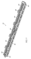
- the printhead assembly 22 shown in Figs. 1 to 4 is adapted to be attached to the underside of the main body 20 to receive ink from the outlets molding 27 (see Fig. 10 of USSN 11/014769 cross referenced above).
- the printhead assembly 22 generally comprises an ink manifold that receives ink from the ink cartridges, or ink storage modules 45 as they are referred to in USSN 11/014769 , and distributes it to the printhead integrated circuits (IC's).
- the ink manifold is made up of an elongate upper member 62 fixed to an elongate lower member 65.
- the upper member 62 is configured to extend beneath the main body 20, between the posts 26.
- a plurality of U-shaped clips 63 project from the upper member 62. These pass through the recesses 37 provided in the rigid plate 34 and become captured by lugs (not shown) formed in the main body 20 to secure the printhead assembly 22.
- the upper element 62 has a plurality of feed tubes 64 that are received within the outlets in the outlet molding 27 when the printhead assembly 22 secures to the main body 20.
- the feed tubes 64 may be provided with an outer coating to guard against ink leakage.
- the upper member 62 is made from a liquid crystal polymer (LCP) which offers a number of advantages. It can be molded so that its coefficient of thermal expansion (CTE) is similar to that of silicon. It will be appreciated that any significant difference in the CTE's of the printhead integrated circuit 74 (discussed below) and the underlying moldings can cause the entire structure to bow. However, as the CTE of LCP in the mold direction is much less than that in the non- mold direction ( ⁇ 5ppm/°C compared to ⁇ 20ppm/°C), care must be take to ensure that the mold direction of the LCP moldings is unidirectional with the longitudinal extent of the printhead integrated circuit (IC) 74. LCP also has a relatively high stiffness with a modulus that is typically 5 times that of 'normal plastics' such as polycarbonates, styrene, nylon, PET and polypropylene.
- LCP also has a relatively high stiffness with a modulus that is typically 5 times that of 'normal plastics' such as poly
- upper member 62 has an open channel configuration for receiving a lower member 65, which is bonded thereto, via an adhesive film 66.
- the lower member 65 is also made from an LCP and has a plurality of ink channels 67 formed along its length. Each of the ink channels 67 receive ink from one of the feed tubes 64, and distribute the ink along the length of the printhead assembly 22.
- the channels are 1 mm wide and separated by 0.75 mm thick walls.
- the lower member 65 has five channels 67 extending along its length. Each channel 67 receives ink from only one of the five feed tubes 64, which in turn receives ink from one of the ink storage modules 45 (see Fig. 10 of USSN 11/014769 cross referenced above).
- adhesive film 66 also acts to seal the individual ink channels 67 to prevent cross channel mixing of the ink when the lower member 65 is assembled to the upper member 62.
- each channel 67 In the bottom of each channel 67 are a series of equi-spaced holes 69 (best seen in Fig. 3 ) to give five rows of holes 69 in the bottom surface of the lower member 65.
- the middle row of holes 69 extends along the centre-line of the lower member 65, directly above the printhead IC 74.
- other rows of holes 69 on either side of the middle row need conduits 70 from each hole 69 to the centre so that ink can be fed to the printhead IC 74.
- the printhead IC 74 is mounted to the underside of the lower member 65 by a polymer sealing film 71.
- This film may be a thermoplastic film such as a PET or Polysulphone film, or it may be in the form of a thermoset film, such as those manufactured by AL technologies and Rogers Corporation.
- the polymer sealing film 71 is a laminate with adhesive layers on both sides of a central film, and laminated onto the underside of the lower member 65. As shown in Figs.
- a plurality of holes 72 are laser drilled through the adhesive film 71 to coincide with the centrally disposed ink delivery points (the middle row of holes 69 and the ends of the conduits 70) for fluid communication between the printhead IC 74 and the channels 67.
- the thickness of the polymer sealing film 71 is critical to the effectiveness of the ink seal it provides. As best seen in Figs. 7 and 8 , the polymer sealing film seals the etched channels 77 on the reverse side of the printhead IC 74, as well as the conduits 70 on the other side of the film. However, as the film 71 seals across the open end of the conduits 70, it can also bulge or sag into the conduit. The section of film that sags into a conduit 70 runs across several of the etched channels 77 in the printhead IC 74. The sagging may cause a gap between the walls separating each of the etched channels 77. Obviously, this breaches the seal and allows ink to leak out of the printhead IC 74 and or between etched channels 77.
- the polymer sealing film 71 should be thick enough to account for any sagging into the conduits 70 while maintaining the seal over the etched channels 77.
- the minimum thickness of the polymer sealing film 71 will depend on:
- a polymer sealing film 71 thickness of 25 microns is adequate for the printhead assembly 22 shown. However, increasing the thickness to 50, 100 or even 200 microns will correspondingly increase the reliability of the seal provided.
- Ink delivery inlets 73 are formed in the 'front' surface of a printhead IC 74.
- the inlets 73 supply ink to respective nozzles (described in Figs. 23 to 36 of USSN 11/014769 cross referenced above) positioned on the inlets.
- the ink must be delivered to the IC's so as to supply ink to each and every individual inlet 73.
- the inlets 73 within an individual printhead IC 74 are physically grouped to reduce ink supply complexity and wiring complexity. They are also grouped logically to minimize power consumption and allow a variety of printing speeds.
- Each printhead IC 74 is configured to receive and print five different colours of ink (C, M, Y, K and IR) and contains 1280 ink inlets per colour, with these nozzles being divided into even and odd nozzles (640 each). Even and odd nozzles for each colour are provided on different rows on the printhead IC 74 and are aligned vertically to perform true 1600 dpi printing, meaning that nozzles 801 are arranged in 10 rows, as clearly shown in Fig. 5 .
- the horizontal distance between two adjacent nozzles 801 on a single row is 31.75 microns, whilst the vertical distance between rows of nozzles is based on the firing order of the nozzles, but rows are typically separated by an exact number of dot lines, plus a fraction of a dot line corresponding to the distance the paper will move between row firing times. Also, the spacing of even and odd rows of nozzles for a given colour must be such that they can share an ink channel, as will be described below.
- the present invention is related to page-width printing and as such the printhead ICs 74 are arranged to extend horizontally across the width of the printhead assembly 22.
- individual printhead ICs 74 are linked together in abutting arrangement across the surface of the adhesive layer 71, as shown in Figs. 2 and 3 .
- the printhead IC's 74 may be attached to the polymer sealing film 71 by heating the IC's above the melting point of the adhesive layer and then pressing them into the sealing film 71, or melting the adhesive layer under the IC with a laser before pressing them into the film. Another option is to both heat the IC (not above the adhesive melting point) and the adhesive layer, before pressing it into the film 71.
- the length of an individual printhead IC 74 is around 20 - 22 mm. To print an A4/US letter sized page, 11 - 12 individual printhead ICs 74 are contiguously linked together. The number of individual printhead ICs 74 may be varied to accommodate sheets of other widths.
- the printhead ICs 74 may be linked together in a variety of ways.
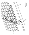
- One particular manner for linking the ICs 74 is shown in Fig. 6 .
- the ICs 74 are shaped at their ends to link together to form a horizontal line of ICs, with no vertical offset between neighboring ICs.
- a sloping join is provided between the ICs having substantially a 45° angle.
- the joining edge is not straight and has a sawtooth profile to facilitate positioning, and the ICs 74 are intended to be spaced about 11 microns apart, measured perpendicular to the joining edge.
- the left most ink delivery nozzles 73 on each row are dropped by 10 line pitches and arranged in a triangle configuration.
- This arrangement provides a degree of overlap of nozzles at the join and maintains the pitch of the nozzles to ensure that the drops of ink are delivered consistently along the printing zone. This arrangement also ensures that more silicon is provided at the edge of the IC 74 to ensure sufficient linkage. Whilst control of the operation of the nozzles is performed by the SoPEC device (discussed later in of USSN 11/014769 cross referenced above), compensation for the nozzles may be performed in the printhead, or may also be performed by the SoPEC device, depending on the storage requirements. In this regard it will be appreciated that the dropped triangle arrangement of nozzles disposed at one end of the IC 74 provides the minimum on-printhead storage requirements. However where storage requirements are less critical, shapes other than a triangle can be used, for example, the dropped rows may take the form of a trapezoid.
- the upper surface of the printhead ICs have a number of bond pads 75 provided along an edge thereof which provide a means for receiving data and or power to control the operation of the nozzles 73 from the SoPEC device.
- fiducials 76 are also provided on the surface of the ICs 74.
- the fiducials 76 are in the form of markers that are readily identifiable by appropriate positioning equipment to indicate the true position of the IC 74 with respect to a neighboring IC and the surface of the adhesive layer 71, and are strategically positioned at the edges of the ICs 74, and along the length of the adhesive layer 71.
- each printhead IC 74 In order to receive the ink from the holes 72 formed in the polymer sealing film 71 and to distribute the ink to the ink inlets 73, the underside of each printhead IC 74 is configured as shown in Fig 7 .
- a number of etched channels 77 are provided, with each channel 77 in fluid communication with a pair of rows of inlets 73 dedicated to delivering one particular colour or type of ink.
- the channels 77 are about 80 microns wide, which is equivalent to the width of the holes 72 in the polymer sealing film 71, and extend the length of the IC 74.
- the channels 77 are divided into sections by silicon walls 78. Each section is directly supplied with ink, to reduce the flow path to the inlets 73 and the likelihood of ink starvation to the individual nozzles. In this regard, each section feeds approximately 128 nozzles 801 via their respective inlets 73.
- Fig. 9 shows more clearly how the ink is fed to the etched channels 77 formed in the underside of the ICs 74 for supply to the nozzles 73.
- holes 72 formed through the polymer sealing film 71 are aligned with one of the channels 77 at the point where the silicon wall 78 separates the channel 77 into sections.
- the holes 72 are about 80 microns in width which is substantially the same width of the channels 77 such that one hole 72 supplies ink to two sections of the channel 77. It will be appreciated that this halves the density of holes 72 required in the polymer sealing film 71.
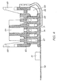
- a flex PCB 79 (see Fig. 4 ) is attached along an edge of the ICs 74 so that control signals and power can be supplied to the bond pads 75 to control and operate the nozzles. As shown more clearly in Fig. 1 , the flex PCB 79 extends from the printhead assembly 22 and folds around the printhead assembly 22.
- the flex PCB 79 may also have a plurality of decoupling capacitors 81 arranged along its length for controlling the power and data signals received. As best shown in Fig. 2 , the flex PCB 79 has a plurality of electrical contacts 180 formed along its length for receiving power and or data signals from the control circuitry of the cradle unit 12. A plurality of holes 80 are also formed along the distal edge of the flex PCB 79 which provide a means for attaching the flex PCB to the flange portion 40 of the rigid plate 34 of the main body 20. The manner in which the electrical contacts of the flex PCB 79 contact the power and data contacts of the cradle unit 12 will be described later.
- a media shield 82 protects the printhead ICs 74 from damage which may occur due to contact with the passing media.
- the media shield 82 is attached to the upper member 62 upstream of the printhead ICs 74 via an appropriate clip-lock arrangement or via an adhesive. When attached in this manner, the printhead ICs 74 sit below the surface of the media shield 82, out of the path of the passing media.
- a space 83 is provided between the media shield 82 and the upper 62 and lower 65 members which can receive pressurized air from an air compressor or the like. As this space 83 extends along the length of the printhead assembly 22, compressed air can be supplied to the space 56 from either end of the printhead assembly 22 and be evenly distributed along the assembly.
- the inner surface of the media shield 82 is provided with a series of fins 84 which define a plurality of air outlets evenly distributed along the length of the media shield 82 through which the compressed air travels and is directed across the printhead ICs 74 in the direction of the media delivery. This arrangement acts to prevent dust and other particulate matter carried with the media from settling on the surface of the printhead ICs, which could cause blockage and damage to the nozzles.
- the present invention gives the user a versatile control system for correcting many of the detrimental conditions that are possible during the operative life of the printer. It is also capable of preparing the printhead for transport, long term storage and re-activation. It can also allow the user to establish a desired negative pressure at the printhead IC nozzles.
- the control system requires easily incorporated modifications to the prior art printer designs described above.
- the printer's maintenance system should meet several requirements:
- Drop ejection for hydration (or keep wet drops) and drop ejection for ink purge require the print engine controller (PEC) to play a roll in the overall printhead maintenance system.
- PEC print engine controller
- the particulate fouling can be dealt with using filters positioned upstream of the printhead. However, care must be taken that small sized filters do not become too much of a flow constriction. By increasing the surface area of the filter the appropriate ink supply rate to the printhead can be maintained.
- Correcting a flooded printhead will typically involve some type of blotting or wiping mechanism to remove beads of ink on the nozzle face of the printhead.
- Methods and systems for removing ink flooded across an ink ejection face of a printhead are described in our earlier filed US application nos. 11/246,707 ("Printhead Maintenance Assembly with Film Transport of Ink”), 11/246,706 ("Method of Maintaining a Printhead using Film Transport of Ink”), 11/246,705 (“Method of Removing Ink from a Printhead using Film Transfer”), and 11/246,708 (“Method of Removing Particulates from a Printhead using Film Transfer”), all filed on October 11, 2005.
- Outgassing is a significant problem for printheads having micron scale fluid flow conduits. Outgassing occurs when gasses dissolved in the ink (typically nitrogen) come out of solution to form bubbles. These bubbles can lodge in the ink line or even the ink ejection chambers and prevent the downstream nozzles from ejecting.
- ink typically nitrogen
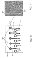
- Figure 10 shows the underside of the LCP moulding 65.
- Conduits 69 extend between the point where the printed IC (not shown) is mounted and the holes 69. Bubbles from outgassing 100 form in the upstream ink line and feed down to the printed IC.
- Figure 11 shows the artifacts that result from outgassing bubbles.
- the nozzles deprime and start ejecting the bubble gas rather than ink. This appears as arrow head shaped artifacts 102 in the resulting print.
- pressure from upstream ink flow eventually clears the bubble from the printhead IC and the artifacts disappear.
- the bubbles 100 can have a tendency to get stuck at conduit discontinuities. Discontinuities such as the silicon wall 78 across the channel 77 in the printhead IC (see Figure 9 ) tend to trap some of the bubbles and effectively form an ink blockage to nozzles fed from that end of the channel 77.
- Color mixing occurs when ink of one color establishes a fluid connection with ink of another color via the face of the nozzle plate. Ink from one ink loan can be driven into the ink loan of a different color by slightly different hydraulic pressures within each line, osmotic pressure differences and even simple diffusion.
- the present invention uses an active control system for the printhead maintenance regime to correct issues as they arise.
- Figure 12 is a schematic representation of the fluid architecture for the printhead shown in Figures 1 to 11 .
- the different ink colors are fed from respective ink tanks 112 to the LCP molding 164 via a filter 160 and pressure regulator 162.
- the inlet 166 to the LCP molding 164 is intermediate the ends of its elongate top molding to assist the ink to evenly fill the length of the channel 67 (see Fig. 10 ).
- From the channels 67, the ink is fed through holes to the smaller conduits 70 (see Fig. 10 ) that lead to the five separate printhead IC's 74.
- This architecture terminates the ink line at the printhead IC 74. Hence any attempts to change the ink flow conditions within the printhead IC 74 need to occur by intervention upstream.
- Figure 13 is a fluid architecture in which the printhead IC 74 is not the end of the ink line.
- the channels 67 in the LCP molding 164 are fed with ink from the ink tank 112 via a filter and pressure regulator 162.
- the inlet 166 to the LCP ink manifold 164 is at one end instead a point intermediate the ends.
- the ink is still fed to the smaller conduits 70 (see Fig. 10 ) and finally the printhead IC's 74.
- the invention provides an ink outlet 172 at the opposite end of the LCP manifold 164 so that the ink line continues downstream to connect the LCP manifold back to the ink tank 112. If necessary, the downstream ink line could lead to an ink sump (not shown) but it will be appreciated that this is an inefficient use of ink.
- the fluidic system can have a branched downstream ink line that can selectively feed to a sump or recirculate back to the ink tank 112. This option is useful if the downstream ink flow is likely to be contaminated with other inks.
- the downstream flow can be initially diverted to the sump until the LCP manifold has been flushed, and then recirculated to the ink tank 112 once again.
- the upstream ink line has a pump 168 driven by motor 170.
- the downstream ink line has a pump 176 driven by another motor 174.
- the upstream and downstream pumps are not two separate pumps, but rather two separate lines running through a single pump. This can be implemented with a six-way peristaltic pump head driven with a single motor.
- the pumps 168 and 176 are shown as separate elements with individual drives 170 and 174.
- the downstream ink line terminates at an ink outlet 180 in the ink tank 112. Returning the ink to the ink tank 112 is, of course, far more efficient than purging it to a waste sump. Using this system, outgassing bubbles can completely bypass the printhead IC 74 in favour of the downstream ink line. Any bubble introduced into the ink line when the ink cartridges are replaced can also be purged. Likewise, the pressure from the upstream pump 168 can be used to recover dried and or clogged nozzles. In fact, all the printhead maintenance requirements listed above can be performed automatically or user initiated with the active control system shown.
- the ink tank 112 has an air inlet 178 so that the LCP manifold can be deprimed of ink if desired.
- Depriming for storage or shipping guards against ink leakage or color mixing between ink lines during period of inactivity (discussed above). It also allows the user to reprime the printhead assembly to a known 'good' state before use or after an inadvertent deprime.
- Depriming the LCP manifold is also useful for cleaning particulates from the exposed face of the printhead IC's 74 by creating an ink foam. By depriming the LCP manifold 164, residual ink remains in the small conduits 70 and the printhead IC's 74.
- the upstream and downstream pumps 114 and 116 can be provided by peristaltic pumps.
- the peristaltic pumps In the printers of the type shown in the above referenced USSN 11/014769 (our docket RRC001US) the peristaltic pumps have a displacement resolution of 10 microliters. This equates to about 5mm of travel on an appropriately dimensional peristaltic tube. These specifications give the most flow rate of about 3 millilitres per minute and very low pulse in the resulting flow.
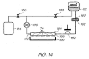
- FIG 14 shows a single pump implementation of the fluidic control system.
- the upstream pump has been replaced with an impulse generator in the form of an accumulator 182.
- the accumulator generates a short pressure burst to prime the fine structures (conduits 70) of the LCP manifold and the printhead IC 74.
- the downstream pump 176 sucks ink into the LCP manifold 164.
- a capping member 190 forms a perimeter seal over the nozzle array.
- the impulse also floods the face of the printhead IC with ink.
- the flooded ink may be removed with mechanisms described in the above referenced FNE27US, FNE28US and FNE29US. Once the nozzle flood has been cleaned, a brief purge print will print out any superficial mixed ink.
- the single pump embodiment uses three valves per color - a sump valve 186, an ink tank valve 188 and the accumulator 182 (which can be open or closed).
- the valves should be zero displacement, zero leak, fast and easy to actuate. Ordinary workers in this field will readily identify a range of suitable valve mechanisms.
- the accumulator will not be zero displacement but the pressure impulse is often required immediately prior to its role as a shut off valve so its displacement is not generally detrimental.
- the fluidic system involves nine valves, three pumps and the perimeter seal on the capper. Hence the control of flow conditions within the printhead assembly is provided using relatively few active components.
Landscapes
- Ink Jet (AREA)
- Ink Jet Recording Methods And Recording Media Thereof (AREA)
- Particle Formation And Scattering Control In Inkjet Printers (AREA)
Claims (8)
- Ein Tintenstrahldrucker, der folgendes umfasst:eine Tintenversorgung (112);einen LCP-Tintenverteiler (164) in Fluidverbindung mit der Tintenversorgung, wobei der LCP-Tintenverteiler einen Tinteneinlass (166) und einen Tintenauslass (172) aufweist;eine Vielzahl von Druckkopf-ICs (74), von denen jede eine Anordnung von Tintenausstoßdüsen besitzt, die an dem LCP-Tintenverteiler (164) angebracht sind;eine nachgeschaltete Pumpe (176) in einer nachgeschalteten Tintenleitung, wobei die nachgeschaltete Tintenleitung die Tintenversorgung (112) und den Tintenauslass (172) verbindet;eine vorgeschaltete Pumpe (168) in einer vorgeschalteten Tintenleitung, wobei die vorgeschaltete Tintenleitung die Tintenversorgung (112) und den Tinteneinlass (166) verbindet; undeinen Gaseinlass, der zur Herstellung einer Fluidverbindung zwischen dem LCP-Tintenverteiler (164) und einer Gasversorgung geöffnet werden kann und zur Bildung eines gasdichten Verschlusses geschlossen werden kann; derart dassder LCP-Tintenverteiler (164) mit Tinte beladen werden kann, wenn der Gaseinlass geschlossen ist; dadurch gekennzeichnet, dass aus dem LCP-Tintenverteiler die Tinte entladen werden kann, wenn der Gaseinlass geöffnet ist, indem die vorgeschaltete Pumpe abgeschaltet und die nachgeschaltete Pumpe betrieben wird.
- Ein Tintenstrahldrucker nach Anspruch 1, wobei die vorgeschaltete und nachgeschaltete Pumpe unabhängig betreibbar sind.
- Ein Tintenstrahldrucker nach Anspruch 1, wobei der Gaseinlass ein Lufteinlass ist, der sich zur Atmosphäre hin öffnen kann.
- Ein Tintenstrahldrucker nach Anspruch 1, wobei die vorgeschaltete und nachgeschaltete Pumpe zum Pumpen von Tinte in eine umgekehrte Richtung reversibel sind.
- Ein Tintenstrahldrucker nach Anspruch 1, wobei die nachgeschaltete Tintenleitung den LCP-Tintenverteiler (164) mit der Tintenversorgung über die nachgeschaltete Pumpe verbindet und der Auslass des Tintenverteilers sich in Fluidverbindung mit einer Gasbelüftung befindet, damit Gas ausgestoßen wird, das in den Tintenverteiler während des Entladens eingesogen wurde.
- Ein Tintenstrahldrucker nach Anspruch 5, wobei sich die Gasbelüftung in der Tintenversorgung befindet.
- Ein Tintenstrahldrucker nach Anspruch 1, wobei die vorgeschaltete Tintenleitung einen Druckregler aufweist, der es gestattet, dass Tinte zu dem Tintenverteiler mit einer vorbestimmten Grenzwert-Druckdifferenz entlang des Druckreglers fließt.
- Ein Tintenstrahldrucker nach Anspruch 1, wobei die vorgeschaltete Pumpe und die nachgeschaltete Pumpe bei unterschiedlichen Durchsätzen arbeiten können.
Applications Claiming Priority (2)
| Application Number | Priority Date | Filing Date | Title |
|---|---|---|---|
| US11/482,982 US7645034B2 (en) | 2006-03-03 | 2006-07-10 | Pulse damped fluidic architecture |
| PCT/AU2006/001067 WO2008006132A1 (en) | 2006-07-10 | 2006-07-31 | Inkjet printhead with controlled de-prime |
Publications (3)
| Publication Number | Publication Date |
|---|---|
| EP2043867A1 EP2043867A1 (de) | 2009-04-08 |
| EP2043867A4 EP2043867A4 (de) | 2009-11-11 |
| EP2043867B1 true EP2043867B1 (de) | 2011-03-02 |
Family
ID=38922826
Family Applications (1)
| Application Number | Title | Priority Date | Filing Date |
|---|---|---|---|
| EP06760924A Ceased EP2043867B1 (de) | 2006-07-10 | 2006-07-31 | Tintenstrahldruckkopf mit gesteuerter entleerung |
Country Status (5)
| Country | Link |
|---|---|
| US (2) | US7645034B2 (de) |
| EP (1) | EP2043867B1 (de) |
| AT (1) | ATE500065T1 (de) |
| DE (1) | DE602006020505D1 (de) |
| WO (1) | WO2008006132A1 (de) |
Families Citing this family (5)
| Publication number | Priority date | Publication date | Assignee | Title |
|---|---|---|---|---|
| WO2007098524A1 (en) * | 2006-03-03 | 2007-09-07 | Silverbrook Research Pty Ltd | Pulse damped fluidic architecture |
| US7645034B2 (en) * | 2006-03-03 | 2010-01-12 | Silverbrook Research Pty Ltd | Pulse damped fluidic architecture |
| DE202007019225U1 (de) * | 2007-08-06 | 2011-05-05 | Pelikan Hardcopy Production Ag | Vorrichtung zur Wiederbefüllung einer Tintenpatrone für einen Tintenstrahldrucker |
| US8079692B2 (en) | 2008-03-03 | 2011-12-20 | Silverbrook Research Pty Ltd | Printer comprising priming/de-priming system with cooperative pushing and pulling of ink through printhead |
| ITVI20120276A1 (it) | 2012-10-19 | 2014-04-20 | New System Srl | Dispositivo di compensazione per una testa di stampa e gruppo di stampa comprendente tale dispositivo di compensazione |
Family Cites Families (34)
| Publication number | Priority date | Publication date | Assignee | Title |
|---|---|---|---|---|
| US4038667A (en) * | 1976-04-28 | 1977-07-26 | Gould Inc. | Ink jet ink supply system |
| JPS56146761A (en) * | 1980-04-17 | 1981-11-14 | Ricoh Co Ltd | Ink jet printing device |
| JPS5839465A (ja) * | 1981-09-02 | 1983-03-08 | Fuji Photo Film Co Ltd | インクジエツトヘツドの目詰り防止方法 |
| GB2112715B (en) | 1981-09-30 | 1985-07-31 | Shinshu Seiki Kk | Ink jet recording apparatus |
| US4494124A (en) | 1983-09-01 | 1985-01-15 | Eastman Kodak Company | Ink jet printer |
| EP0178884A3 (de) * | 1984-10-15 | 1988-04-20 | Dataproducts Corporation | Farbstrahlgerät und Verfahren zum Betrieb |
| JPS62292438A (ja) * | 1986-06-13 | 1987-12-19 | Canon Inc | インクジエツト記録装置 |
| JPS6387241A (ja) * | 1986-09-30 | 1988-04-18 | Nec Corp | インクジエツトプリンタ装置用キヤツプ機構 |
| DE3713794A1 (de) * | 1987-04-24 | 1988-11-10 | Siemens Ag | Vorrichtung zum reinigen und verschliessen der duesenflaeche eines tintenkopfes |
| CA2009631C (en) * | 1989-02-17 | 1994-09-20 | Shigeo Nonoyama | Pressure damper of an ink jet printer |
| DE69333481T2 (de) | 1992-10-09 | 2005-03-24 | Canon K.K. | Tintenstrahldrukkopf und damit versehene Druckvorrichtung |
| EP0604942B1 (de) * | 1992-12-28 | 1997-10-29 | Canon Kabushiki Kaisha | Tintenstrahlaufzeichnungsgerät |
| US5592201A (en) * | 1994-04-28 | 1997-01-07 | Hewlett-Packard Company | Manual priming pump for inkjet printing mechanisms |
| JPH11207993A (ja) * | 1998-01-22 | 1999-08-03 | Toshiba Tec Corp | インクジェットプリンタ |
| ES1040834Y (es) | 1998-08-07 | 1999-10-16 | Investronica Sistemas S A | Dispositivo del circuito de alimentacion de tinta en maquinas de dibujo raster. |
| JP4350187B2 (ja) * | 1999-01-14 | 2009-10-21 | 株式会社キーエンス | インクジェット記録装置 |
| DE60118464T2 (de) * | 2000-01-18 | 2006-12-07 | Seiko Epson Corp. | Tintenpatrone, tintenstrahlaufzeichnungsgerät mit einer solchen tintenpatrone und reinigungssteuerungsverfahren für aufzeichnungskopf des aufzeichnungsgerätes |
| WO2002034523A2 (en) | 2000-10-23 | 2002-05-02 | Aprion Digital Ltd. | A closed ink delivery system with print head ink pressure control and method of same |
| AUPR399601A0 (en) * | 2001-03-27 | 2001-04-26 | Silverbrook Research Pty. Ltd. | An apparatus and method(ART108) |
| DE60303227T2 (de) | 2002-02-15 | 2006-09-28 | Brother Kogyo K.K., Nagoya | Verfahren zur Herstellung eines Tintenstrahlkopfes |
| US6869160B2 (en) | 2002-10-04 | 2005-03-22 | Eastman Kodak Company | Purge shutdown for a solvent ink printing system |
| US7364279B2 (en) * | 2004-03-26 | 2008-04-29 | Brother Kogyo Kabushiki Kaisha | Ink-jet printer with air-discharge-flow assuring means |
| US20050023156A1 (en) * | 2003-07-30 | 2005-02-03 | Ramsey J. Michael | Nanostructured material transport devices and their fabrication by application of molecular coatings to nanoscale channels |
| US7210771B2 (en) | 2004-01-08 | 2007-05-01 | Eastman Kodak Company | Ink delivery system with print cartridge, container and reservoir apparatus and method |
| US7182449B2 (en) * | 2004-01-21 | 2007-02-27 | Fuji Photo Film Co., Ltd. | Inkjet recording apparatus |
| JP4599878B2 (ja) * | 2004-04-16 | 2010-12-15 | コニカミノルタホールディングス株式会社 | インクジェットプリンタ |
| US7213902B2 (en) | 2004-05-05 | 2007-05-08 | Eastman Kodak Company | Method of shutting down a continuous ink jet printer for maintaining positive pressure at the printhead |
| CN100429080C (zh) * | 2004-06-30 | 2008-10-29 | 兄弟工业株式会社 | 图像记录设备 |
| EP1769921B1 (de) | 2004-07-07 | 2012-02-29 | Konica Minolta Medical & Graphic, Inc. | Tintenstrahldrucker |
| JP4564838B2 (ja) * | 2004-12-28 | 2010-10-20 | キヤノン株式会社 | インクジェット記録装置 |
| JP4635618B2 (ja) * | 2005-01-19 | 2011-02-23 | セイコーエプソン株式会社 | 充填方法、及び液体吐出装置 |
| US7467858B2 (en) * | 2005-10-12 | 2008-12-23 | Hewlett-Packard Development Company, L.P. | Back pressure control in inkjet printing |
| US7645034B2 (en) * | 2006-03-03 | 2010-01-12 | Silverbrook Research Pty Ltd | Pulse damped fluidic architecture |
| WO2007098524A1 (en) * | 2006-03-03 | 2007-09-07 | Silverbrook Research Pty Ltd | Pulse damped fluidic architecture |
-
2006
- 2006-07-10 US US11/482,982 patent/US7645034B2/en active Active
- 2006-07-31 EP EP06760924A patent/EP2043867B1/de not_active Ceased
- 2006-07-31 DE DE602006020505T patent/DE602006020505D1/de active Active
- 2006-07-31 AT AT06760924T patent/ATE500065T1/de not_active IP Right Cessation
- 2006-07-31 WO PCT/AU2006/001067 patent/WO2008006132A1/en not_active Ceased
-
2009
- 2009-12-29 US US12/648,888 patent/US20100103234A1/en not_active Abandoned
Also Published As
| Publication number | Publication date |
|---|---|
| US20100103234A1 (en) | 2010-04-29 |
| DE602006020505D1 (de) | 2011-04-14 |
| EP2043867A1 (de) | 2009-04-08 |
| US7645034B2 (en) | 2010-01-12 |
| ATE500065T1 (de) | 2011-03-15 |
| EP2043867A4 (de) | 2009-11-11 |
| WO2008006132A1 (en) | 2008-01-17 |
| US20070206068A1 (en) | 2007-09-06 |
Similar Documents
| Publication | Publication Date | Title |
|---|---|---|
| US7841708B2 (en) | Fludically controlled inkjet printhead | |
| US8459785B2 (en) | Inkjet printhead with pressure pulse priming | |
| EP1991423B1 (de) | Drucker mit aktiver fluidarchitektur | |
| KR101365347B1 (ko) | 고정형 프린트헤드 및 가동 진공 플래튼을 구비한 프린팅 시스템 | |
| KR100918334B1 (ko) | 잉크젯 프린트헤드 제조방법 | |
| JP6708415B2 (ja) | 液体吐出装置、および液体吐出装置の制御方法 | |
| JP3800807B2 (ja) | インクジェット記録装置 | |
| JP2013067111A (ja) | 液体噴射ヘッド及び液体噴射装置 | |
| EP2043867A1 (de) | Tintenstrahldruckkopf mit gesteuerter entleerung | |
| JP2017124618A (ja) | 液体吐出装置および液体吐出方法 | |
| US12583221B2 (en) | Liquid ejection head and liquid ejection apparatus comprising the same | |
| US12617205B2 (en) | Liquid ejection head and manufacturing method of liquid ejection head | |
| KR101037015B1 (ko) | 유지보수 벨트를 갖는 프린트헤드 유지보수 스테이션 | |
| JP3901202B2 (ja) | インクジェット記録装置 | |
| US8293057B2 (en) | Double laser drilling of a printhead integrated circuit attachment film | |
| JP2000313123A (ja) | インクジェット記録ヘッド、インクジェット記録装置、およびインクジェット記録ヘッドの吐出回復方法 | |
| JP2006069113A (ja) | インクジェット記録ヘッド、インクジェット記録装置、およびインクジェット記録ヘッドのメンテナンス方法 | |
| JP2014151564A (ja) | 液体噴射ヘッドおよび液体噴射装置 |
Legal Events
| Date | Code | Title | Description |
|---|---|---|---|
| PUAI | Public reference made under article 153(3) epc to a published international application that has entered the european phase |
Free format text: ORIGINAL CODE: 0009012 |
|
| 17P | Request for examination filed |
Effective date: 20090206 |
|
| AK | Designated contracting states |
Kind code of ref document: A1 Designated state(s): AT BE BG CH CY CZ DE DK EE ES FI FR GB GR HU IE IS IT LI LT LU LV MC NL PL PT RO SE SI SK TR |
|
| AX | Request for extension of the european patent |
Extension state: AL BA HR MK RS |
|
| A4 | Supplementary search report drawn up and despatched |
Effective date: 20090915 |
|
| 17Q | First examination report despatched |
Effective date: 20091028 |
|
| GRAP | Despatch of communication of intention to grant a patent |
Free format text: ORIGINAL CODE: EPIDOSNIGR1 |
|
| GRAS | Grant fee paid |
Free format text: ORIGINAL CODE: EPIDOSNIGR3 |
|
| GRAA | (expected) grant |
Free format text: ORIGINAL CODE: 0009210 |
|
| AK | Designated contracting states |
Kind code of ref document: B1 Designated state(s): AT BE BG CH CY CZ DE DK EE ES FI FR GB GR HU IE IS IT LI LT LU LV MC NL PL PT RO SE SI SK TR |
|
| REG | Reference to a national code |
Ref country code: GB Ref legal event code: FG4D |
|
| REG | Reference to a national code |
Ref country code: CH Ref legal event code: EP |
|
| REG | Reference to a national code |
Ref country code: IE Ref legal event code: FG4D |
|
| REF | Corresponds to: |
Ref document number: 602006020505 Country of ref document: DE Date of ref document: 20110414 Kind code of ref document: P |
|
| REG | Reference to a national code |
Ref country code: DE Ref legal event code: R096 Ref document number: 602006020505 Country of ref document: DE Effective date: 20110414 |
|
| REG | Reference to a national code |
Ref country code: NL Ref legal event code: VDEP Effective date: 20110302 |
|
| PG25 | Lapsed in a contracting state [announced via postgrant information from national office to epo] |
Ref country code: LT Free format text: LAPSE BECAUSE OF FAILURE TO SUBMIT A TRANSLATION OF THE DESCRIPTION OR TO PAY THE FEE WITHIN THE PRESCRIBED TIME-LIMIT Effective date: 20110302 Ref country code: LV Free format text: LAPSE BECAUSE OF FAILURE TO SUBMIT A TRANSLATION OF THE DESCRIPTION OR TO PAY THE FEE WITHIN THE PRESCRIBED TIME-LIMIT Effective date: 20110302 Ref country code: GR Free format text: LAPSE BECAUSE OF FAILURE TO SUBMIT A TRANSLATION OF THE DESCRIPTION OR TO PAY THE FEE WITHIN THE PRESCRIBED TIME-LIMIT Effective date: 20110603 Ref country code: ES Free format text: LAPSE BECAUSE OF FAILURE TO SUBMIT A TRANSLATION OF THE DESCRIPTION OR TO PAY THE FEE WITHIN THE PRESCRIBED TIME-LIMIT Effective date: 20110613 Ref country code: SE Free format text: LAPSE BECAUSE OF FAILURE TO SUBMIT A TRANSLATION OF THE DESCRIPTION OR TO PAY THE FEE WITHIN THE PRESCRIBED TIME-LIMIT Effective date: 20110302 |
|
| LTIE | Lt: invalidation of european patent or patent extension |
Effective date: 20110302 |
|
| PG25 | Lapsed in a contracting state [announced via postgrant information from national office to epo] |
Ref country code: SI Free format text: LAPSE BECAUSE OF FAILURE TO SUBMIT A TRANSLATION OF THE DESCRIPTION OR TO PAY THE FEE WITHIN THE PRESCRIBED TIME-LIMIT Effective date: 20110302 Ref country code: FI Free format text: LAPSE BECAUSE OF FAILURE TO SUBMIT A TRANSLATION OF THE DESCRIPTION OR TO PAY THE FEE WITHIN THE PRESCRIBED TIME-LIMIT Effective date: 20110302 Ref country code: CY Free format text: LAPSE BECAUSE OF FAILURE TO SUBMIT A TRANSLATION OF THE DESCRIPTION OR TO PAY THE FEE WITHIN THE PRESCRIBED TIME-LIMIT Effective date: 20110302 Ref country code: AT Free format text: LAPSE BECAUSE OF FAILURE TO SUBMIT A TRANSLATION OF THE DESCRIPTION OR TO PAY THE FEE WITHIN THE PRESCRIBED TIME-LIMIT Effective date: 20110302 Ref country code: NL Free format text: LAPSE BECAUSE OF FAILURE TO SUBMIT A TRANSLATION OF THE DESCRIPTION OR TO PAY THE FEE WITHIN THE PRESCRIBED TIME-LIMIT Effective date: 20110302 Ref country code: BG Free format text: LAPSE BECAUSE OF FAILURE TO SUBMIT A TRANSLATION OF THE DESCRIPTION OR TO PAY THE FEE WITHIN THE PRESCRIBED TIME-LIMIT Effective date: 20110602 |
|
| PG25 | Lapsed in a contracting state [announced via postgrant information from national office to epo] |
Ref country code: BE Free format text: LAPSE BECAUSE OF FAILURE TO SUBMIT A TRANSLATION OF THE DESCRIPTION OR TO PAY THE FEE WITHIN THE PRESCRIBED TIME-LIMIT Effective date: 20110302 |
|
| PG25 | Lapsed in a contracting state [announced via postgrant information from national office to epo] |
Ref country code: EE Free format text: LAPSE BECAUSE OF FAILURE TO SUBMIT A TRANSLATION OF THE DESCRIPTION OR TO PAY THE FEE WITHIN THE PRESCRIBED TIME-LIMIT Effective date: 20110302 Ref country code: PT Free format text: LAPSE BECAUSE OF FAILURE TO SUBMIT A TRANSLATION OF THE DESCRIPTION OR TO PAY THE FEE WITHIN THE PRESCRIBED TIME-LIMIT Effective date: 20110704 |
|
| PG25 | Lapsed in a contracting state [announced via postgrant information from national office to epo] |
Ref country code: SK Free format text: LAPSE BECAUSE OF FAILURE TO SUBMIT A TRANSLATION OF THE DESCRIPTION OR TO PAY THE FEE WITHIN THE PRESCRIBED TIME-LIMIT Effective date: 20110302 Ref country code: RO Free format text: LAPSE BECAUSE OF FAILURE TO SUBMIT A TRANSLATION OF THE DESCRIPTION OR TO PAY THE FEE WITHIN THE PRESCRIBED TIME-LIMIT Effective date: 20110302 Ref country code: CZ Free format text: LAPSE BECAUSE OF FAILURE TO SUBMIT A TRANSLATION OF THE DESCRIPTION OR TO PAY THE FEE WITHIN THE PRESCRIBED TIME-LIMIT Effective date: 20110302 Ref country code: IS Free format text: LAPSE BECAUSE OF FAILURE TO SUBMIT A TRANSLATION OF THE DESCRIPTION OR TO PAY THE FEE WITHIN THE PRESCRIBED TIME-LIMIT Effective date: 20110702 |
|
| PLBE | No opposition filed within time limit |
Free format text: ORIGINAL CODE: 0009261 |
|
| STAA | Information on the status of an ep patent application or granted ep patent |
Free format text: STATUS: NO OPPOSITION FILED WITHIN TIME LIMIT |
|
| 26N | No opposition filed |
Effective date: 20111205 |
|
| PG25 | Lapsed in a contracting state [announced via postgrant information from national office to epo] |
Ref country code: MC Free format text: LAPSE BECAUSE OF NON-PAYMENT OF DUE FEES Effective date: 20110731 Ref country code: PL Free format text: LAPSE BECAUSE OF FAILURE TO SUBMIT A TRANSLATION OF THE DESCRIPTION OR TO PAY THE FEE WITHIN THE PRESCRIBED TIME-LIMIT Effective date: 20110302 Ref country code: DK Free format text: LAPSE BECAUSE OF FAILURE TO SUBMIT A TRANSLATION OF THE DESCRIPTION OR TO PAY THE FEE WITHIN THE PRESCRIBED TIME-LIMIT Effective date: 20110302 |
|
| REG | Reference to a national code |
Ref country code: CH Ref legal event code: PL |
|
| REG | Reference to a national code |
Ref country code: DE Ref legal event code: R097 Ref document number: 602006020505 Country of ref document: DE Effective date: 20111205 |
|
| PG25 | Lapsed in a contracting state [announced via postgrant information from national office to epo] |
Ref country code: CH Free format text: LAPSE BECAUSE OF NON-PAYMENT OF DUE FEES Effective date: 20110731 Ref country code: LI Free format text: LAPSE BECAUSE OF NON-PAYMENT OF DUE FEES Effective date: 20110731 |
|
| PG25 | Lapsed in a contracting state [announced via postgrant information from national office to epo] |
Ref country code: IT Free format text: LAPSE BECAUSE OF FAILURE TO SUBMIT A TRANSLATION OF THE DESCRIPTION OR TO PAY THE FEE WITHIN THE PRESCRIBED TIME-LIMIT Effective date: 20110302 |
|
| PG25 | Lapsed in a contracting state [announced via postgrant information from national office to epo] |
Ref country code: LU Free format text: LAPSE BECAUSE OF NON-PAYMENT OF DUE FEES Effective date: 20110731 |
|
| PG25 | Lapsed in a contracting state [announced via postgrant information from national office to epo] |
Ref country code: TR Free format text: LAPSE BECAUSE OF FAILURE TO SUBMIT A TRANSLATION OF THE DESCRIPTION OR TO PAY THE FEE WITHIN THE PRESCRIBED TIME-LIMIT Effective date: 20110302 |
|
| PG25 | Lapsed in a contracting state [announced via postgrant information from national office to epo] |
Ref country code: HU Free format text: LAPSE BECAUSE OF FAILURE TO SUBMIT A TRANSLATION OF THE DESCRIPTION OR TO PAY THE FEE WITHIN THE PRESCRIBED TIME-LIMIT Effective date: 20110302 |
|
| REG | Reference to a national code |
Ref country code: GB Ref legal event code: 732E Free format text: REGISTERED BETWEEN 20140619 AND 20140625 |
|
| REG | Reference to a national code |
Ref country code: DE Ref legal event code: R081 Ref document number: 602006020505 Country of ref document: DE Owner name: MEMJET TECHNOLOGY LIMITED, IE Free format text: FORMER OWNER: SILVERBROOK RESEARCH PTY. LTD., BALMAIN, NEW SOUTH WALES, AU Effective date: 20141016 |
|
| REG | Reference to a national code |
Ref country code: FR Ref legal event code: CA Effective date: 20141118 Ref country code: FR Ref legal event code: CD Owner name: MEMJET TECHNOLOGY LIMITED, IE Effective date: 20141118 Ref country code: FR Ref legal event code: TP Owner name: MEMJET TECHNOLOGY LIMITED, IE Effective date: 20141118 |
|
| REG | Reference to a national code |
Ref country code: FR Ref legal event code: PLFP Year of fee payment: 10 |
|
| REG | Reference to a national code |
Ref country code: FR Ref legal event code: PLFP Year of fee payment: 11 |
|
| REG | Reference to a national code |
Ref country code: FR Ref legal event code: PLFP Year of fee payment: 12 |
|
| REG | Reference to a national code |
Ref country code: FR Ref legal event code: PLFP Year of fee payment: 13 |
|
| PGFP | Annual fee paid to national office [announced via postgrant information from national office to epo] |
Ref country code: IE Payment date: 20200727 Year of fee payment: 15 |
|
| PG25 | Lapsed in a contracting state [announced via postgrant information from national office to epo] |
Ref country code: IE Free format text: LAPSE BECAUSE OF NON-PAYMENT OF DUE FEES Effective date: 20210731 |
|
| PGFP | Annual fee paid to national office [announced via postgrant information from national office to epo] |
Ref country code: FR Payment date: 20220725 Year of fee payment: 17 |
|
| P01 | Opt-out of the competence of the unified patent court (upc) registered |
Effective date: 20230414 |
|
| PGFP | Annual fee paid to national office [announced via postgrant information from national office to epo] |
Ref country code: GB Payment date: 20230727 Year of fee payment: 18 |
|
| PGFP | Annual fee paid to national office [announced via postgrant information from national office to epo] |
Ref country code: DE Payment date: 20230727 Year of fee payment: 18 |
|
| PG25 | Lapsed in a contracting state [announced via postgrant information from national office to epo] |
Ref country code: FR Free format text: LAPSE BECAUSE OF NON-PAYMENT OF DUE FEES Effective date: 20230731 |
|
| REG | Reference to a national code |
Ref country code: DE Ref legal event code: R119 Ref document number: 602006020505 Country of ref document: DE |
|
| GBPC | Gb: european patent ceased through non-payment of renewal fee |
Effective date: 20240731 |
|
| PG25 | Lapsed in a contracting state [announced via postgrant information from national office to epo] |
Ref country code: DE Free format text: LAPSE BECAUSE OF NON-PAYMENT OF DUE FEES Effective date: 20250201 |
|
| PG25 | Lapsed in a contracting state [announced via postgrant information from national office to epo] |
Ref country code: GB Free format text: LAPSE BECAUSE OF NON-PAYMENT OF DUE FEES Effective date: 20240731 |