EP1991423B1 - Drucker mit aktiver fluidarchitektur - Google Patents
Drucker mit aktiver fluidarchitektur Download PDFInfo
- Publication number
- EP1991423B1 EP1991423B1 EP07701517A EP07701517A EP1991423B1 EP 1991423 B1 EP1991423 B1 EP 1991423B1 EP 07701517 A EP07701517 A EP 07701517A EP 07701517 A EP07701517 A EP 07701517A EP 1991423 B1 EP1991423 B1 EP 1991423B1
- Authority
- EP
- European Patent Office
- Prior art keywords
- ink
- printhead
- valve
- downstream
- upstream
- Prior art date
- Legal status (The legal status is an assumption and is not a legal conclusion. Google has not performed a legal analysis and makes no representation as to the accuracy of the status listed.)
- Not-in-force
Links
Images


Classifications
-
- B—PERFORMING OPERATIONS; TRANSPORTING
- B41—PRINTING; LINING MACHINES; TYPEWRITERS; STAMPS
- B41J—TYPEWRITERS; SELECTIVE PRINTING MECHANISMS, i.e. MECHANISMS PRINTING OTHERWISE THAN FROM A FORME; CORRECTION OF TYPOGRAPHICAL ERRORS
- B41J2/00—Typewriters or selective printing mechanisms characterised by the printing or marking process for which they are designed
- B41J2/005—Typewriters or selective printing mechanisms characterised by the printing or marking process for which they are designed characterised by bringing liquid or particles selectively into contact with a printing material
- B41J2/01—Ink jet
- B41J2/17—Ink jet characterised by ink handling
- B41J2/175—Ink supply systems ; Circuit parts therefor
-
- B—PERFORMING OPERATIONS; TRANSPORTING
- B41—PRINTING; LINING MACHINES; TYPEWRITERS; STAMPS
- B41J—TYPEWRITERS; SELECTIVE PRINTING MECHANISMS, i.e. MECHANISMS PRINTING OTHERWISE THAN FROM A FORME; CORRECTION OF TYPOGRAPHICAL ERRORS
- B41J2/00—Typewriters or selective printing mechanisms characterised by the printing or marking process for which they are designed
- B41J2/005—Typewriters or selective printing mechanisms characterised by the printing or marking process for which they are designed characterised by bringing liquid or particles selectively into contact with a printing material
- B41J2/01—Ink jet
- B41J2/135—Nozzles
- B41J2/14—Structure thereof only for on-demand ink jet heads
-
- B—PERFORMING OPERATIONS; TRANSPORTING
- B41—PRINTING; LINING MACHINES; TYPEWRITERS; STAMPS
- B41J—TYPEWRITERS; SELECTIVE PRINTING MECHANISMS, i.e. MECHANISMS PRINTING OTHERWISE THAN FROM A FORME; CORRECTION OF TYPOGRAPHICAL ERRORS
- B41J2/00—Typewriters or selective printing mechanisms characterised by the printing or marking process for which they are designed
- B41J2/005—Typewriters or selective printing mechanisms characterised by the printing or marking process for which they are designed characterised by bringing liquid or particles selectively into contact with a printing material
- B41J2/01—Ink jet
- B41J2/135—Nozzles
- B41J2/145—Arrangement thereof
- B41J2/155—Arrangement thereof for line printing
-
- B—PERFORMING OPERATIONS; TRANSPORTING
- B41—PRINTING; LINING MACHINES; TYPEWRITERS; STAMPS
- B41J—TYPEWRITERS; SELECTIVE PRINTING MECHANISMS, i.e. MECHANISMS PRINTING OTHERWISE THAN FROM A FORME; CORRECTION OF TYPOGRAPHICAL ERRORS
- B41J2/00—Typewriters or selective printing mechanisms characterised by the printing or marking process for which they are designed
- B41J2/005—Typewriters or selective printing mechanisms characterised by the printing or marking process for which they are designed characterised by bringing liquid or particles selectively into contact with a printing material
- B41J2/01—Ink jet
- B41J2/17—Ink jet characterised by ink handling
- B41J2/1707—Conditioning of the inside of ink supply circuits, e.g. flushing during start-up or shut-down
-
- B—PERFORMING OPERATIONS; TRANSPORTING
- B41—PRINTING; LINING MACHINES; TYPEWRITERS; STAMPS
- B41J—TYPEWRITERS; SELECTIVE PRINTING MECHANISMS, i.e. MECHANISMS PRINTING OTHERWISE THAN FROM A FORME; CORRECTION OF TYPOGRAPHICAL ERRORS
- B41J2/00—Typewriters or selective printing mechanisms characterised by the printing or marking process for which they are designed
- B41J2/005—Typewriters or selective printing mechanisms characterised by the printing or marking process for which they are designed characterised by bringing liquid or particles selectively into contact with a printing material
- B41J2/01—Ink jet
- B41J2/17—Ink jet characterised by ink handling
- B41J2/175—Ink supply systems ; Circuit parts therefor
- B41J2/17503—Ink cartridges
- B41J2/17556—Means for regulating the pressure in the cartridge
-
- B—PERFORMING OPERATIONS; TRANSPORTING
- B41—PRINTING; LINING MACHINES; TYPEWRITERS; STAMPS
- B41J—TYPEWRITERS; SELECTIVE PRINTING MECHANISMS, i.e. MECHANISMS PRINTING OTHERWISE THAN FROM A FORME; CORRECTION OF TYPOGRAPHICAL ERRORS
- B41J2/00—Typewriters or selective printing mechanisms characterised by the printing or marking process for which they are designed
- B41J2/005—Typewriters or selective printing mechanisms characterised by the printing or marking process for which they are designed characterised by bringing liquid or particles selectively into contact with a printing material
- B41J2/01—Ink jet
- B41J2/17—Ink jet characterised by ink handling
- B41J2/175—Ink supply systems ; Circuit parts therefor
- B41J2/17596—Ink pumps, ink valves
-
- B—PERFORMING OPERATIONS; TRANSPORTING
- B41—PRINTING; LINING MACHINES; TYPEWRITERS; STAMPS
- B41J—TYPEWRITERS; SELECTIVE PRINTING MECHANISMS, i.e. MECHANISMS PRINTING OTHERWISE THAN FROM A FORME; CORRECTION OF TYPOGRAPHICAL ERRORS
- B41J2/00—Typewriters or selective printing mechanisms characterised by the printing or marking process for which they are designed
- B41J2/005—Typewriters or selective printing mechanisms characterised by the printing or marking process for which they are designed characterised by bringing liquid or particles selectively into contact with a printing material
- B41J2/01—Ink jet
- B41J2/135—Nozzles
- B41J2/14—Structure thereof only for on-demand ink jet heads
- B41J2002/14419—Manifold
-
- B—PERFORMING OPERATIONS; TRANSPORTING
- B41—PRINTING; LINING MACHINES; TYPEWRITERS; STAMPS
- B41J—TYPEWRITERS; SELECTIVE PRINTING MECHANISMS, i.e. MECHANISMS PRINTING OTHERWISE THAN FROM A FORME; CORRECTION OF TYPOGRAPHICAL ERRORS
- B41J2/00—Typewriters or selective printing mechanisms characterised by the printing or marking process for which they are designed
- B41J2/005—Typewriters or selective printing mechanisms characterised by the printing or marking process for which they are designed characterised by bringing liquid or particles selectively into contact with a printing material
- B41J2/01—Ink jet
- B41J2/135—Nozzles
- B41J2/14—Structure thereof only for on-demand ink jet heads
- B41J2002/14491—Electrical connection
-
- B—PERFORMING OPERATIONS; TRANSPORTING
- B41—PRINTING; LINING MACHINES; TYPEWRITERS; STAMPS
- B41J—TYPEWRITERS; SELECTIVE PRINTING MECHANISMS, i.e. MECHANISMS PRINTING OTHERWISE THAN FROM A FORME; CORRECTION OF TYPOGRAPHICAL ERRORS
- B41J2202/00—Embodiments of or processes related to ink-jet or thermal heads
- B41J2202/01—Embodiments of or processes related to ink-jet heads
- B41J2202/19—Assembling head units
-
- B—PERFORMING OPERATIONS; TRANSPORTING
- B41—PRINTING; LINING MACHINES; TYPEWRITERS; STAMPS
- B41J—TYPEWRITERS; SELECTIVE PRINTING MECHANISMS, i.e. MECHANISMS PRINTING OTHERWISE THAN FROM A FORME; CORRECTION OF TYPOGRAPHICAL ERRORS
- B41J2202/00—Embodiments of or processes related to ink-jet or thermal heads
- B41J2202/01—Embodiments of or processes related to ink-jet heads
- B41J2202/20—Modules
Definitions
- the present invention relates to the field of printing and in particular inkjet printing.
- Inkjet printing is a popular and versatile form of print imaging.
- the Assignee has developed printers that eject ink through MEMS printhead IC's.
- These printhead IC's integrated circuits are formed using lithographic etching and deposition techniques used for semiconductor fabrication.
- micro-scale nozzle structures in MEMS printhead IC's allow a high nozzle density (nozzles per unit of IC surface area), high print resolutions, low power consumption, self cooling operation and therefore high print speeds.
- Such printheads are described in detail in US 10/160273 (MJ40US) and US 10/728804 (MTBOOIUS) to the present Assignee.
- the small nozzle structures and high nozzle densities can create difficulties with nozzle clogging, de-priming, nozzle drying (decap), color mixing, nozzle flooding, bubble contamination in the ink stream and so on.
- Each of these issues can produce artifacts that are detrimental to the print quality.
- the component parts of the printer are designed to minimize the risk that these problems will occur. The optimum situation would be printer components whose inherent function is able to preclude these problem issues from arising. In reality, the many different types of operating conditions, and mishaps or unduly rough handling during transport or day to day operation, make it impossible to address the above problems via the 'passive' control of component design, material selection and so on.
- EP 0,968,829 discloses a method and apparatus for removing air from an inkjet print cartridge by collecting the air in a predetermined area and forcing the air from the air collection area using a conduit.
- a first embodiment of the invention provides an inkjet printer as detailed in claim 1.
- Advantageous embodiments are provided in the dependent claims.
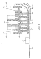
- the printhead assembly 22 shown in Figs. 1 to 4 is adapted to be attached to the underside of the main body 20 to receive ink from the outlets molding 27 (see Fig. 10 of USSN 11/014769 , our docket RRC001US).
- the printhead assembly 22 generally comprises an elongate upper member 62 which is configured to extend beneath the main body 20 between the posts 26.
- U-shaped clips 63 project from the upper member 62. These pass through the recesses 37 provided in the rigid plate 34 and become captured by lugs (not shown) formed in the main body 20 to secure the printhead assembly 22.
- the upper element 62 has a plurality of feed tubes 64 that are received within the outlets in the outlet molding 27 when the printhead assembly 22 secures to the main body 20.
- the feed tubes 64 may be provided with an outer coating to guard against ink leakage.
- the upper member 62 is made from a liquid crystal polymer (LCP) which offers a number of advantages. It can be molded so that its coefficient of thermal expansion (CTE) is similar to that of silicon. It will be appreciated that any significant difference in the CTE's of the printhead integrated circuit 74 (discussed below) and the underlying moldings can cause the entire structure to bow. However, as the CTE of LCP in the mold direction is much less than that in the non- mold direction ( ⁇ 5ppm/°C compared to ⁇ 20ppm/°C), care must be take to ensure that the mold direction of the LCP moldings is unidirectional with the longitudinal extent of the printhead integrated circuit (IC) 74. LCP also has a relatively high stiffness with a modulus that is typically 5 times that of 'normal plastics' such as polycarbonates, styrene, nylon, PET and polypropylene.
- LCP also has a relatively high stiffness with a modulus that is typically 5 times that of 'normal plastics' such as poly
- upper member 62 has an open channel configuration for receiving a lower member 65, which is bonded thereto, via an adhesive film 66.
- the lower member 65 is also made from an LCP and has a plurality of ink channels 67 formed along its length. Each of the ink channels 67 receive ink from one of the feed tubes 64, and distribute the ink along the length of the printhead assembly 22.
- the channels are 1 mm wide and separated by 0.75 mm thick walls.
- the lower member 65 has five channels 67 extending along its length. Each channel 67 receives ink from only one of the five feed tubes 64, which in turn receives ink from one of the ink storage modules 45 (see Fig. 10 of USSN 11/014769 , our docket RRC001US) to reduce the risk of mixing different colored inks.
- adhesive film 66 also acts to seal the individual ink channels 67 to prevent cross channel mixing of the ink when the lower member 65 is assembled to the upper member 62.
- each channel 67 In the bottom of each channel 67 are a series of equi-spaced holes 69 (best seen in Fig. 3 ) to give five rows of holes 69 in the bottom surface of the lower member 65.
- the middle row of holes 69 extends along the centre-line of the lower member 65, directly above the printhead IC 74.
- other rows of holes 69 on either side of the middle row need conduits 70 from each hole 69 to the centre so that ink can be fed to the printhead IC 74.
- the printhead IC 74 is mounted to the underside of the lower member 65 by a polymer sealing film 71.
- This film may be a thermoplastic film such as a PET or Polysulphone film, or it may be in the form of a thermoset film, such as those manufactured by AL technologies and Rogers Corporation.
- the polymer sealing film 71 is a laminate with adhesive layers on both sides of a central film, and laminated onto the underside of the lower member 65. As shown in Figs.
- a plurality of holes 72 are laser drilled through the adhesive film 71 to coincide with the centrally disposed ink delivery points (the middle row of holes 69 and the ends of the conduits 70) for fluid communication between the printhead IC 74 and the channels 67.
- the thickness of the polymer sealing film 71 is critical to the effectiveness of the ink seal it provides. As best seen in Figs. 7 and 8 , the polymer sealing film seals the etched channels 77 on the reverse side of the printhead IC 74, as well as the conduits 70 on the other side of the film. However, as the film 71 seals across the open end of the conduits 70, it can also bulge or sag into the conduit. The section of film that sags into a conduit 70 runs across several of the etched channels 77 in the printhead IC 74. The sagging may cause a gap between the walls separating each of the etched channels 77. Obviously, this breaches the seal and allows ink to leak out of the printhead IC 74 and or between etched channels 77.
- the polymer sealing film 71 should be thick enough to account for any sagging into the conduits 70 while maintaining the seal over the etched channels 77.
- the minimum thickness of the polymer sealing film 71 will depend on:
- a polymer sealing film 71 thickness of 25 microns is adequate for the printhead assembly 22 shown. However, increasing the thickness to 50, 100 or even 200 microns will correspondingly increase the reliability of the seal provided.
- Ink delivery inlets 73 are formed in the 'front' surface of a printhead IC 74.
- the inlets 73 supply ink to respective nozzles (described in Figs. 23 to 36 of USSN 11/014769 , our docket RRC001US) positioned on the inlets.
- the ink must be delivered to the IC's so as to supply ink to each and every individual inlet 73.
- the inlets 73 within an individual printhead IC 74 are physically grouped to reduce ink supply complexity and wiring complexity. They are also grouped logically to minimize power consumption and allow a variety of printing speeds.
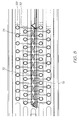
- Each printhead IC 74 is configured to receive and print five different colours of ink (C, M, Y, K and IR) and contains 1280 ink inlets per colour, with these nozzles being divided into even and odd nozzles (640 each). Even and odd nozzles for each colour are provided on different rows on the printhead IC 74 and are aligned vertically to perform true 1600 dpi printing, meaning that nozzles 801 are arranged in 10 rows, as clearly shown in Fig. 5 .
- the horizontal distance between two adjacent nozzles 801 on a single row is 31.75 microns, whilst the vertical distance between rows of nozzles is based on the firing order of the nozzles, but rows are typically separated by an exact number of dot lines, plus a fraction of a dot line corresponding to the distance the paper will move between row firing times. Also, the spacing of even and odd rows of nozzles for a given colour must be such that they can share an ink channel, as will be described below.
- the present invention is related to page-width printing and as such the printhead ICs 74 are arranged to extend horizontally across the width of the printhead assembly 22.
- individual printhead ICs 74 are linked together in abutting arrangement across the surface of the adhesive layer 71, as shown in Figs. 2 and 3 .
- the printhead IC's 74 may be attached to the polymer sealing film 71 by heating the IC's above the melting point of the adhesive layer and then pressing them into the sealing film 71, or melting the adhesive layer under the IC with a laser before pressing them into the film. Another option is to both heat the IC (not above the adhesive melting point) and the adhesive layer, before pressing it into the film 71.
- the length of an individual printhead IC 74 is around 20 - 22 mm. To print an A4/US letter sized page, 11 - 12 individual printhead ICs 74 are contiguously linked together. The number of individual printhead ICs 74 may be varied to accommodate sheets of other widths.
- the printhead ICs 74 may be linked together in a variety of ways.
- One particular manner for linking the ICs 74 is shown in Fig. 6 .
- the ICs 74 are shaped at their ends to link together to form a horizontal line of ICs, with no vertical offset between neighboring ICs.
- a sloping join is provided between the ICs having substantially a 45° angle.
- the joining edge is not straight and has a sawtooth profile to facilitate positioning, and the ICs 74 are intended to be spaced about 11 microns apart, measured perpendicular to the joining edge.
- the left most ink delivery nozzles 73 on each row are dropped by 10 line pitches and arranged in a triangle configuration.
- This arrangement provides a degree of overlap of nozzles at the join and maintains the pitch of the nozzles to ensure that the drops of ink are delivered consistently along the printing zone. This arrangement also ensures that more silicon is provided at the edge of the IC 74 to ensure sufficient linkage. Whilst control of the operation of the nozzles is performed by the SoPEC device (discussed later in of USSN 11 /014769 , our docket RRC001US), compensation for the nozzles may be performed in the printhead, or may also be performed by the SoPEC device, depending on the storage requirements. In this regard it will be appreciated that the dropped triangle arrangement of nozzles disposed at one end of the IC 74 provides the minimum on-printhead storage requirements. However where storage requirements are less critical, shapes other than a triangle can be used, for example, the dropped rows may take the form of a trapezoid.
- the upper surface of the printhead ICs have a number of bond pads 75 provided along an edge thereof which provide a means for receiving data and or power to control the operation of the nozzles 73 from the SoPEC device.
- fiducials 76 are also provided on the surface of the ICs 74.
- the fiducials 76 are in the form of markers that are readily identifiable by appropriate positioning equipment to indicate the true position of the IC 74 with respect to a neighboring IC and the surface of the adhesive layer 71, and are strategically positioned at the edges of the ICs 74, and along the length of the adhesive layer 71.
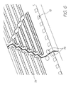
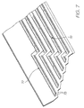
- each printhead IC 74 In order to receive the ink from the holes 72 formed in the polymer sealing film 71 and to distribute the ink to the ink inlets 73, the underside of each printhead IC 74 is configured as shown in Fig 7 .
- a number of etched channels 77 are provided, with each channel 77 in fluid communication with a pair of rows of inlets 73 dedicated to delivering one particular colour or type of ink.
- the channels 77 are about 80 microns wide, which is equivalent to the width of the holes 72 in the polymer sealing film 71, and extend the length of the IC 74.
- the channels 77 are divided into sections by silicon walls 78. Each section is directly supplied with ink, to reduce the flow path to the inlets 73 and the likelihood of ink starvation to the individual nozzles. In this regard, each section feeds approximately 128 nozzles 801 via their respective inlets 73.
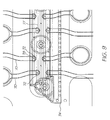
- Fig. 9 shows more clearly how the ink is fed to the etched channels 77 formed in the underside of the ICs 74 for supply to the nozzles 73.
- holes 72 formed through the polymer sealing film 71 are aligned with one of the channels 77 at the point where the silicon wall 78 separates the channel 77 into sections.
- the holes 72 are about 80 microns in width which is substantially the same width of the channels 77 such that one hole 72 supplies ink to two sections of the channel 77. It will be appreciated that this halves the density of holes 72 required in the polymer sealing film 71.
- a flex PCB 79 (see Fig. 4 ) is attached along an edge of the ICs 74 so that control signals and power can be supplied to the bond pads 75 to control and operate the nozzles. As shown more clearly in Fig. 1 , the flex PCB 79 extends from the printhead assembly 22 and folds around the printhead assembly 22.
- the flex PCB 79 may also have a plurality of decoupling capacitors 81 arranged along its length for controlling the power and data signals received. As best shown in Fig. 2 , the flex PCB 79 has a plurality of electrical contacts 180 formed along its length for receiving power and or data signals from the control circuitry of the cradle unit 12. A plurality of holes 80 are also formed along the distal edge of the flex PCB 79 which provide a means for attaching the flex PCB to the flange portion 40 of the rigid plate 34 of the main body 20. The manner in which the electrical contacts of the flex PCB 79 contact the power and data contacts of the cradle unit 12 will be described later.
- a media shield 82 protects the printhead ICs 74 from damage which may occur due to contact with the passing media.
- the media shield 82 is attached to the upper member 62 upstream of the printhead ICs 74 via an appropriate clip-lock arrangement or via an adhesive. When attached in this manner, the printhead ICs 74 sit below the surface of the media shield 82, out of the path of the passing media.
- a space 83 is provided between the media shield 82 and the upper 62 and lower 65 members which can receive pressurized air from an air compressor or the like. As this space 83 extends along the length of the printhead assembly 22, compressed air can be supplied to the space 56 from either end of the printhead assembly 22 and be evenly distributed along the assembly.
- the inner surface of the media shield 82 is provided with a series of fins 84 which define a plurality of air outlets evenly distributed along the length of the media shield 82 through which the compressed air travels and is directed across the printhead ICs 74 in the direction of the media delivery. This arrangement acts to prevent dust and other particulate matter carried with the media from settling on the surface of the printhead ICs, which could cause blockage and damage to the nozzles.
- the present invention gives the user a versatile control system for correcting many of the detrimental conditions that are possible during the operative life of the printer. It is also capable of preparing the printhead for transport, long term storage and reactivation. It can also allow the user to establish a desired negative pressure at the printhead IC nozzles.
- the control system requires easily incorporated modifications to the prior art printer designs described above.
- the printer's maintenance system should meet several requirements:
- Drop ejection for hydration (or keep wet drops) and drop ejection for ink purge require the print engine controller (PEC) to play a roll in the overall printhead maintenance system.
- PEC print engine controller
- the particulate fouling can be dealt with using filters positioned upstream of the printhead. However, care must be taken that small sized filters do not become too much of a flow constriction. By increasing the surface area of the filter the appropriate ink supply rate to the printhead can be maintained.
- Correcting a flooded printhead will typically involve some type of blotting or wiping mechanism to remove beads of ink on the nozzle face of the printhead.
- Methods and systems for removing ink flooded across an ink ejection face of a printhead are described in our earlier filed US application nos. 11/246,707 ('Printhead Maintenance Assembly with Film Transport of Ink'), 11/246,706 ('Method of Maintaining a Printhead using Film Transport of Ink'), 11/246,705 ('Method of Removing Ink from a Printhead using Film Transfer'), and 11/246,708 ('Method of Removing Particulates from a Printhead using Film Transfer'), all filed on October 11, 2005.
- Outgassing is a significant problem for printheads having micron scale fluid flow conduits. Outgassing occurs when gasses dissolved in the ink (typically nitrogen) come out of solution to form bubbles. These bubbles can lodge in the ink line or even the ink ejection chambers and prevent the downstream nozzles from ejecting.
- ink typically nitrogen
- Figure 10 shows the underside of the LCP moulding 65.
- Conduits 69 extend between the point where the printed IC (not shown) is mounted and the holes 69. Bubbles from outgassing 100 form in the upstream ink line and feed down to the printed IC.
- Figure 11 shows the artifacts that result from outgassing bubbles.
- the nozzles deprime and start ejecting the bubble gas rather than ink. This appears as arrow head shaped artifacts 102 in the resulting print.
- pressure from upstream ink flow eventually clears the bubble from the printhead IC and the artifacts disappear.
- the bubbles 100 can have a tendency to get stuck at conduit discontinuities. Discontinuities such as the silicon wall 78 across the channel 77 in the printhead IC (see Figure 9 ) tend to trap some of the bubbles and effectively form an ink blockage to nozzles fed from that end of the channel 77.
- Color mixing occurs when ink of one color establishes a fluid connection with ink of another color via the face of the nozzle plate. Ink from one ink loan can be driven into the ink loan of a different color by slightly different hydraulic pressures within each line, osmotic pressure differences and even simple diffusion.
- the present invention uses an active control system for the printhead maintenance regime to correct issues as they arise.
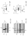
- Figures 12A and 12B are a schematic representation of the fluid architecture for the printhead shown in Figures 1 to 11 .
- the different ink colors are fed to the channels 67 in an LCP moulding and fed through holes 69 to the smaller conduits 70 that lead to the printhead IC 74.
- this architecture terminates the ink line at the printhead IC 74. Hence any attempts to change the ink flow conditions within the printhead IC 74 need to occur by intervention upstream.
- Figures 13A and 13B sketch a fluid ink architecture in which the printhead IC 74 is not the end of the ink line.
- the small conduits 70 in the LCP moulding do not terminate at the holes feeding the printhead IC 74 but rather continue on to downstream channels 108 feeding holes 110 into downstream channels 106 in the LCP moulding. In this way bubbles in the ink line do not need to be purged out through the printhead IC 74. Instead the bubbles can completely bypass the printhead IC 74 in favor of the downstream ink conduits 108.
- the ink line upstream of the printhead IC 74 has a pump 114 as does the downstream ink line 116. This provides the control system with even greater flexibility for creating desired flow conditions within the ink line in general and the printhead IC 74 in particular.
- the downstream pump 116 feeds to sump 118 and this highlights that the fluid architecture of the present system creates more waste ink than the architecture sketched in Figures 12A and 12B .
- Figure 14 is a schematic section view through the LCP moulding, the polymer sealing film 21 and the printhead IC 74. It illustrates the ink flow from the LCP channel 67 to the upstream conduit 70 past the inlet 72 (see Figure 9 ) to the printhead IC 74 to the downstream ink conduit 108 but feeds the downstream LCP channel 106. It will be appreciated that the upstream conduit 17 and the downstream conduit 108 are essentially a single conduit 120.
- Figures 15A, 15B and 15C illustrate how the walls of the conduits 120 can be profiled to better control the position of any bubbles that inevitably contaminate the ink line.
- Figure 15A shows two conduits 120 feeding ink between the upstream LCP channel 67 and the downstream LCP channel 106 both conduits have bubbles contaminating the ink flow.
- bubble 126 in the left hand conduit 120 is significantly smaller than the bubble 124 in the right hand conduit.
- the upstream conduit 70 from the printhead IC towards the upstream LCP channel 67 the bubble 124 is forced to have part of its surface with a higher radius of curvature 122.
- the smaller bubble 126 has a relatively large radius of curvature 128.
- the higher degree of curvature at 122 creates a stronger capillary force for drawing ink down the upstream end 70 of the right hand ink conduit 120.
- the ink conduit 120 can be used to move ink bubbles 100 past the printhead IC 74 to minimise the amount of bubble contamination within the ejection nozzles and chambers.
- the bubble 100 By tapering the sides of the ink conduit 120 from the downstream LCP channel 106 to the upstream LCP channel 67, the bubble 100 will tend to have a smaller radius of curvature 122 at its downstream end than its upstream end 128. Because of the surface tension and capillarity the bubble 100 is biased towards the downstream LCP channel 106 and so tends not to become lodged at the inlets to the printhead IC 74.
- the printhead IC 74 may draw in small amounts of the air bubble 100 but it is not forced to expel the entire bubble as with the architecture shown in Figures 12A and 12B .
- both of the upstream and downstream pumps 114 and 116 have a shutoff valve in a parallel bypass line (113 and 132 respectively).
- the controller sets both shutoff valves 113 and 132 to 'close'.
- the upstream pump 114 pushes ink through the upstream LCP channel 67 and down the upstream end of the conduits 120.
- the downstream pump 116 is driven at a slightly higher rate. Typically it operates at about 20% more capacity than the upstream pump 114.
- the upstream pump has a lower capacity than the downstream pump the difference in the flow rate is made up by air drawn in through the printhead IC 74. This ensures that the fluidic architecture is primed with ink up to the back of the printhead IC 74 and all bubble contaminants removed from the upstream LCP channel 67 and upstream conduits 70.
- FIG 17 shows the system configuration for depriming the architecture downstream with the printhead IC 74.
- Both the shut off valves 113 and 132 are closed while the upstream pump is deactivated. When either pump is deactivated, it essentially acts as a closed shutoff valve. This means that the upstream end of the ink line is choked of any ink supply. Meanwhile the downstream pump 116 slowly draws any ink out of the downstream ends 108 of the conduits 120 and the downstream LCP channel 106. Eventually the downstream pump 116 is simply drawing air through the printhead IC 74. This configuration ensures that the system has be deprimed downstream of the printhead IC 74.
- FIG 18 shows the system configuration for depriming the fluid architecture upstream of the printhead IC 74.
- the upstream shut off valve 130 is closed and the upstream pump is operating in reverse.
- the downstream shut off valve 132 is open and the downstream pump 116 is deactivated.
- the upstream pump 114 draws any ink through the upstream lines 70 and 67 back towards the cartridge (not shown).
- the open shut off valve 132 will allow some of the ink in the downstream end of the ink lines 106 and 108. However, eventually the upstream pump 114 draws air only through the upstream conduits 70 and 67 from the printhead IC 74.
- FIG 19 shows the system configuration for creating a desired negative pressure that the printhead IC 74.
- the advantages of having a negative hydrostatic pressure at the nozzles of the printhead IC are discussed in details in the above referenced USSN 11/014769 (Docket No. RRC001US) filed December 20, 2004.
- Both the upstream and downstream shut off valves 113 and 132 are open. However, the upstream pump 114 is deactivated and acts as a closed shut off valve. Downstream of the printhead IC 74 the downstream pump 116 is activated but operates relatively slowly. As the shut off valve 132 is open the downstream valve 116 creates a flow circulating from the pump through the downstream shut off valve 132 and the returning back through the pump 116. As the upstream shut off valve 130 is open a small amount of ink from the downstream conduits 108 and 106 are drawn into the circulating loop of ink by Venturi effects. For conservation of flow, a small amount of ink bleeds off to the sump.
- FIG. 20 the configuration for ink flow through or 'purge' is shown.
- the upstream shut off valve 130 is closed however the upstream pump 114 is activated and supplying the upstream conduit 67 and 70 with ink.
- the downstream shut off valve 132 is open while the downstream pump 116 is deactivated and therefore closing that branch of the fluid system.
- This configuration draws ink directly from the supply and feeds it to the sump. This involves some degree of ink wastage however it purges the entire architecture of bubbles caused by outgassing.
- Figure 21 shows the configuration needed to purge the printhead IC 74.
- the downstream pump 116 and downstream shut off valve 132 are deactivated and closed. This essentially creates a flow obstruction downstream of the printhead IC 74.
- the upstream pump 114 is activated but the upstream shut off valve 130 is closed. This forces ink out of the nozzles in the printhead IC until it beads and collects on the surface of the nozzle face. From there, the purged ink can be collected and transported to the sump using a mechanism such as those described in the above referenced co-pending applications filed in the US ( USSN 11/246707 , our docket no. FNE001US) filed on October 11, 2005.
- the active control system in by the present fluidic architecture offers a versatile range of operations that allow the user to recover the printhead whenever artifacts are noticed. It also allows the manufacturer to ship the printhead IC's deprimed so that the user primes them on initial start up. For example after final print testing of the printhead assemblies are shipped dry. The control system is used to deprime upstream and then deprime downstream of the printhead IC 74.
- the configuration shown in Figure 16 is used to prime upstream then the configuration of Figure 20 creates a flow through condition after which the configuration of Figure 19 establishes a negative pressure at the printhead IC.
- the configuration of Figure 19 can maintain a desired negative pressure condition at the printhead nozzles.
- the user can deprime downstream then prime upstream followed by establishing a negative pressure.
- the user can perform a flow through purge as illustrated in Figure 20 .
- control system can flood the printhead as shown in Figure 21 before re-establishing a negative pressure as shown in Figure 19 .
- control system can be set to automatically deprime downstream of the printhead IC before the capper places a perimeter seal around the printhead IC.
- the upstream and downstream pumps 114 and 116 can be provided by peristaltic pumps.
- the peristaltic pumps In the printers of the type shown in the above referenced USSN 11/014769 (our docket RRC001US) the peristaltic pumps have a displacement resolution of 10 microliters. This equates to about 5mm of travel on an appropriately dimensional peristaltic tube. These specifications give the most flow rate of about 3 millilitres per minute and very low pulse in the resulting flow.
- valves should preferably be zero displacement, zero leak, fast and easy to actuate. Ordinary workers in this field will readily identify a range of valve mechanisms that satisfy these requirements.
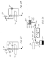
- Figure 22 shows a first single pump implementation of the fluidic control system.
- This implementation uses four shut off valves 134, 135, 136 and 137 in order to direct ink flows past the printhead IC 74 and eventually to the sump 118.
- Set out in Table 1 below are the operational statuses for each of the valves and the pump in order to provide the various control states within the architecture.
- In relation to the pump status column 'down' is an indication that the peristaltic pump 114 is driving ink flow downwards as shown in Figure 22 and 'up' indicates ink flow upwards as it appears in Figure 22 .
- Figure 23 shows a second single pump implementation that uses only two valves to achieve all the control states possible in the above described implementations.
- the valves 138 and 140 are 3-way valves and therefore slightly more expensive components.
- Table 2 below sets out the operational status for each of the system components in order to achieve the flow conditions achieved by the two pump implementation.
- Table 2 Single Pump to Valve Implementation Function Pump 114 Valve 138 Valve 140 Prime Down Inline Inline Print Up Inline Recirculate Flush Down Inline Bypass Flood Down Inline Recirculate Deprime Downstream Down Recirculate Inline Deprime upstream Up Inline Recirculate Standby Up Recirculate Recircutate
- Figure 24 shows a third single pump implementation that further simplifies the fluidic architecture. It will be appreciated that only a single ink line is shown and a color printer would have separate lines (and of course separate ink tanks 112) for each ink color. As shown in Figure 24 , this architecture has a single pump 114 downstream of the LCP moulding 164, and a shut off valve 138 upstream of the LCP moulding. The LCP moulding supports the printhead IC's 74 via the adhesive polymer film 71 (see Fig. 2 ). The shut off valve 138 isolates the ink in the ink tank 112 from the printhead IC's 74 whenever the printer is powered down. This prevents any color mixing at the printhead IC's 74 from reaching the ink tank 112 during periods of inactivity. These issues are discussed in more detail below with reference to the shut off valve shown in Figures 29 and 30 .
- the ink tank 112 has a venting bubble point pressure regulator 200 for maintaining a relatively constant negative hydrostatic pressure in the ink at the nozzles.
- Bubble point pressure regulators within ink reservoirs are comprehensively described in co-pending application no. 11/640355 (Our Docket RMC007US) filed 18 December 2006. However, for the purposes of this description the regulator 202 is shown as a bubble outlet 204 submerged in the ink of the tank 112 and vented to atmosphere via sealed conduit 204 extending to an air inlet 206.
- the pressure in the tank 112 drops until the pressure difference at the bubble outlet 202 sucks air into the tank.
- This air forms a forms a bubble in the ink which rises to the tank's headspace.
- This pressure difference is the bubble point pressure and will depend on the diameter (or smallest dimension) of the bubble outlet 202 and the Laplace pressure of the ink meniscus at the outlet which is resisting the ingress of the air.
- the bubble point regulator uses the bubble point pressure needed to generate a bubble at the submerged bubble outlet 202 to keep the hydrostatic pressure at the outlet substantially constant (there are slight fluctuations when the bulging meniscus of air forms a bubble and rises to the headspace in the ink tank). If the hydrostatic pressure at the outlet is at the bubble point, then the hydrostatic pressure profile in the ink tank is also known regardless of how much ink has been consumed from the tank. The pressure at the surface of the ink in the tank will decrease towards the bubble point pressure as the ink level drops to the outlet. Of course, once the outlet 202 is exposed, the head space vents to atmosphere and negative pressure is lost. The ink tank should be refilled, or replaced (if it is a cartridge) before the ink level reaches the bubble outlet 202.
- the ink tank 112 can be a fixed reservoir that can be refilled, a replaceable cartridge or (as disclosed in USSN 11/014769 our docket no. RRC001US) a refillable cartridge.
- the outlet 162 of the ink tank 112 has a filter 160.
- some printers may incorporate a filter downstream of the printhead IC 74 as well. However, as filters have a finite life, replacing old filters by simply replacing the ink cartridge is particularly convenient for the user. If the upstream and or downstream filters are a separate consumable item, regular replacement relies on the user's diligence.
- the hydrostatic pressure at the nozzles is also constant and less than atmospheric.
- the shut off valve 138 has been closed for a period of time, outgassing bubbles may form in the LCP moulding 164 or the printhead IC's 74 that change the pressure at the nozzles.
- expansion and contraction of the bubbles from diurnal temperature variations can change the pressure in the ink line 67 downstream of the shut off valve 138.
- the pressure in the ink tank can vary during periods of inactivity because of dissolved gases coming out of solution.
- the downstream ink line 106 leading from the LCP 164 to the pump 114 can include an ink sensor 152 linked to an electronic controller 154 for the pump.
- the sensor 152 senses the presence or absence of ink in the downstream ink line 106.
- the system can dispense with the sensor 152, and the pump 114 can be configured so that it runs for an appropriate period of time for each of the various operations. This may adversely affect the operating costs because of increased ink wastage.
- the pump 114 feeds into a sump 184 (when pumping in the forward direction).
- the sump 184 is physically positioned in the printer so that it is less elevated than the printhead ICs 74. This allows the column of ink in the downstream ink line 106 to 'hang' from the LCP 164 during standby periods, thereby creating a negative hydrostatic pressure at the printhead ICs 74. A negative pressure at the nozzles draws the ink meniscus inwards and inhibits color mixing.
- the peristaltic pump 114 needs to be stopped in an open condition so that there is fluid communication between the LCP 164 and the ink outlet in the sump 184.
- shut off valve 138 isolates the ink tank 112 from the nozzle of the printhead IC's 74 to prevent color mixing extending up to the ink tank 112. Once the ink in the tank has been contaminated with a different color, it is irretrievable and has to be replaced. This is discussed further below in relation to the shut off valve's ability to maintain the integrity of its seal when the pressure difference between the upstream and downstream sides of the valve is very small.
- the capper 150 is a printhead maintenance station that seals the nozzles during standby periods to avoid dehydration of the printhead ICs 74 as well as shield the nozzle plate from paper dust and other particulates.
- the capper 150 is also configured to wipe the nozzle plate to remove dried ink and other contaminants. Dehydration of the printhead ICs 74 occurs when the ink solvent, typically water, evaporates and increases the viscosity of the ink. If the ink viscosity is too high, the ink ejection actuators fail to eject ink drops. Should the capper seal be compromised, dehydrated nozzles can be a problem when reactivating the printer after a power down or standby period.
- the printheads (or fully assembled printers) are shipped deprimed of ink. Priming a new dry printhead upon installation is shown in Figs 25A and 25B .
- the capper 150 is applied to the printhead ICs 74 and the shut off valve 138 is initially closed. As shown in Fig 25A , there is no ink in the upstream LCP channels 70 or the downstream LCP channels 108.
- An ink sensor 156 at the peristaltic pump 114 registers the absence of ink to the controller 154.
- the shut off valve 138 is opened and the pump 114 pumps forward (from ink tank 112 to sump 184). Ink is infused into the upstream and downstream channels 70 and 108 of the LCP moulding. Ink feeds into the printhead ICs 74 by capillary action.
- the multi-channel pump 114 (one channel per color) stops when the sensor 156 for all the ink lines register the presence of ink.
- the nozzles may be fired into the capper 150 to drop the pressure at the bubble outlet 202 to the bubble point pressure.
- simply printing the print job soon draws the pressure in the ink tank 112 down to the normal operating pressure.
- shut off valve 138 protects the ink tank 112 from contamination. Mixing downstream of the shut off valve 138 can be easily rectified during the 'Standby-to-Ready' procedure described below.
- the nozzles is in fluid communication with the waste ink outlet at the sump 184.
- the weight of ink in the downstream ink line 106 generates a negative pressure at the nozzles.
- a negative pressure at the nozzles creates a concave meniscus that is less prone to wick out onto the nozzle plate.
- Fig 26A shows the printer in standby.
- the shut off valve 138 is closed and the pump 114 is open.
- the capper 150 is sealed over the printhead ICs 74. If the printer has been in standby for a relatively short time (say, overnight), the ink will have dehydrated to a degree, but probably not to the point where the nozzles have dried out. However, even mild dehydration can visibly concentrate the ink and there may also be some color mixing.
- Fig 26B shows the system configuration for purging the ink upstream of the printhead ICs.
- the shut off valve 138 is opened and the pump 114 is moved to a closed position (no fluid communication between the printhead ICs 74 and the sump 184).
- the printhead ICs 74 need to print a burst of dots with the capper 150 remaining in place to blot the purged ink.
- the volume of ink to be purged will depend on the printer, but as an indication the printhead shown in Figs 1 and 2 needs to print the equivalent of about 10% to 30% of a page in process black.
- the printhead may be primed by dehydrated through to the LCP moulding supporting the printhead ICs 74.
- the printhead ICs need to be primed with ejectable ink.
- Fig 26C shows the process for achieving this.
- the pump 114 With the shut off valve 138 closed, the pump 114 is driven in reverse a small amount to force an ink flood 158 onto the nozzle plate of each IC 74.
- the capper 150 wipes the printhead ICs 74 to distribute the flood 158 across the nozzle plate, while firing the nozzles to prevent any ink migrating back into the LCP moulding. If this is not immediately successful, the process can be repeated until all the nozzles rehydrate.
- the shut off valve 138 is opened (see Fig 26E ) and the pump 114 drives forward again and stops at the open position.
- the nozzles in the printhead ICs 74 are fired one last time to ensure there is no color mixing from wiping the ink flood across the nozzle plate.
- Figs 27A and 27B show the procedure for a controlled power down (i.e. the user switching off the main power switch). This would be used when the user is moving the printer, placing it in storage or similar.
- a controlled power down i.e. the user switching off the main power switch.
- the printhead ICs 74 are deprimed.
- the shut off valve 138 is closed, while the capper 150 unseals the printhead ICs 74 and the pump 114 pumps forward to the sump.
- air drawn through the nozzles deprimes the printhead ICs 74 and the downstream ink line to the pump 114.
- the pump 114 stops at the closed position and the capper 150 seals the printhead ICs.
- shut off valve 138 In the event of sudden failure of the power supply, the shut off valve 138 is biased to close. This prevents any color mixing in the ink tank.
- the pump 114 may be open or closed and the capper 150 may be sealed or unsealed depending on the printer status at the time of power failure. However, as long as the shut off valve closes to protect the ink tank, all other conditions can be rectified by the user when the power is restored.
- Figs 28A to 28C show the process for switching the printer on after a power down period.
- the worst case is assumed - thoroughly mixed ink downstream of the shut off valve 138 to the pump 114. Referring to Fig 28A this is fixed by depriming the printhead ICs 74 and the downstream line to the pump 114.
- the shut off valve 138 remains closed while the capper 150 unseals the nozzles and the pump 114 pumps the ink forward to the sump.
- the capper 150 reads a lack of ink, the capper 150 reseals the printhead ICs 74 and the shut off valve 138 opens as shown in Fig 28B .
- the ink upstream of the printhead ICs 74 is flushed through to the pump 114.
- the shut off valve closed, and the pump 114 can be stopped, preferably in the open condition so that the hydrostatic pressure at the nozzles is less than atmospheric.
- the printer is now in Standby and to print, it simply initiates the Standby to Ready procedure discussed above.
- the user can quickly address the problem by sealing the nozzles with the capper, opening the shut off valve 138 and pumping forward (as shown in Fig 28 B) .
- the LCP moulding refills with ink which infuses to the printhead ICs.
- the user should immediately follow the Power Up procedure shown in Figs 28A to 28C .
- the printhead IC deprime and subsequent reprime recovers the printer from most failure states (albeit not in the most ink economical way) and so may be the most frequently used remedy by the user.
- the ink tank 112 should be kept fluidically isolated.
- shut off valve 138 needs to be biased closed. Any power down should stop any fluid communication between the ink tank and the printhead ICs 74. It is important that the fluid seal in the valve be reliable as a small compromise to the seal will allow contaminants to migrate to the ink tank during long periods of printer inactivity. This is difficult when the pressure difference across the valve is very small as is the case in the upstream ink line. A large pressure difference tends to clamp the movable valve member against the valve seat, thereby assisting the integrity of the seal.
- the valve 138 shown in Figs 29 and 30 opens and shuts the upstream ink line for each color simultaneously.
- the valve body 200 defines inlet channels 202 leading from the ink tank (not shown). Outlet channels 67 lead to the LCP moulding (not shown).
- An actuator arm 204 is pivoted to the valve body so that a multi valve lifter 208 raises the valve stems 210 when an actuation force 206 is applied.
- Fig 30 is a partial section view showing a single valve.
- the valve member 212 seals against the valve seat 216 under the biasing action of the diaphragm 214.
- the actuation force 206 works against the diaphragm bias to lift the valve stem 210 and unseat the valve member 214.
- the actuator arm 204 is a first class lever so the actuator force 206 uses a mechanical advantage to lift the stems 210.
- valve body 212 is a resilient material such as polyurethane for fluid tight sealing against the valve seat 216.
- the valve stem 210 has a flanged metal pin 218 fitted into an axial recess 220. This ensures the valve lifter 208 does not simply slip off the end of the stem 210 by compressing the (relatively) soft resilient material of the valve member 212.
- the diaphragm 214 has another important advantage in that it increases the interior volume of the ink line when the valve opens.
- the relatively large surface area of the diaphragm 214 creates suction in the ink line as it lifts up to unseat the valve member 216.
- creating some suction in the upstream ink line will assist the ink tank to drop to the pressure where the bubble point regulator (see Fig 24 ) controls the negative pressure at the printhead ICs.
- closing the valve slowly avoids sending a pulse through the ink line.
- the reduction in the internal volume caused by lowering the diaphragm is absorbed by raising the level in the ink tank.
- the actuator should open the valve faster than it closes the valve.
- a solenoid with damped return stroke may be used.
- Another simple actuator uses a shape memory alloy.
- a shape memory alloy, such as NitinolTM wire, tends to inherently damp its return stroke.
- a heating current drive the initial martensitic to austenitic phase change, but it reverts to martensite by conductive cooling which tends to be slower. This slow phase change can be used avoid pressure pulses at the printhead IC
Landscapes
- Ink Jet (AREA)
- Particle Formation And Scattering Control In Inkjet Printers (AREA)
- Accessory Devices And Overall Control Thereof (AREA)
- Manipulation Of Pulses (AREA)
- Power Conversion In General (AREA)
- Devices For Checking Fares Or Tickets At Control Points (AREA)
Claims (6)
- Ein Tintenstrahldrucker, der folgendes umfasst:einen Tintenbehälter (112);einen integrierten Schaltkreis (IC) (74) eines Druckkopfes in Fluidverbindung mit dem Tintenbehälter (112) über eine vorgeschaltete Tintenleitung, wobei der Druckkopf-IC eine Anordnung von Düsen aufweist, von denen jede entsprechende Aktuatoren zum Ausstoßen von Tintentröpfchen auf Druckmedien besitzt;einen Alttintenauslass (184) in Fluidverbindung mit dem Druckkopf-IC über eine nachgeschaltete Tintenleitung (106);ein vorgeschaltetes Absperrventil (138) in der vorgeschalteten Tintenleitung, wobei das Absperrventil ein Diaphragma (214) umfasst, das in Richtung auf eine Sperrposition vorgespannt ist; undeinen nachgeschalteten Pumpmechanismus (114) in der nachgeschalteten Tintenleitung;und dadurch gekennzeichnet ist, dass:ein Bläschenpunkt-Druckregler (200) in dem Tintenbehälter (112) positioniert ist; unddas Diaphragma (214) konfiguriert ist, um Tinte zu verdrängen, wenn es sich zu der Sperrposition bewegt, so dass beim Öffnen des Absperrventils ein endliches Volumen an Tinte aus dem Tintenbehälter herausgezogen wird, damit der hydrostatische Druck an einem Bläschenauslass (202) des Bläschenpunkt-Druckreglers in Richtung auf den Bläschenpunktdruck gesenkt wird.
- Ein Tintenstrahldrucker nach Anspruch 1, wobei der Pumpmechanismus eine reversible Schlauchpumpe (114) ist.
- Ein Tintenstrahldrucker nach Anspruch 1, der ferner einen dem Druckkopf-IC (74) vorgeschalteten Filter (160) zum Entfernen von Feinstoffen aus der Tinte umfasst.
- Ein Tintenstrahldrucker nach Anspruch 3, wobei der Tintenbehälter (112) einen Auslass in abgedichteter Fluidverbindung mit dem Absperrventil (138) aufweist und der Filter (160) in dem Tintenbehälter positioniert ist, wobei der Auslass bedeckt wird.
- Ein Tintenstrahldrucker nach Anspruch 1, der ferner einen dem Druckkopf-IC (74) nachgeschalteten Sensor (152) zum Erfassen des Vorhandenseins oder Fehlens von Tinte umfasst.
- Ein Tintenstrahldrucker nach Anspruch 1, wobei der Bläschenpunkt-Druckregler (200) einen Luftbläschenauslass, der in die Tinte in dem Tintenbehälter eintaucht, und einen zur Atmosphäre hin belüfteten Lufteinlass aufweist, so dass eine beliebige Verringerung des hydrostatischen Druckes in dem Tintenbehälter aufgrund des Tintenverbrauchs Luft durch den Lufteinlass zur Bildung von Bläschen an dem Bläschenauslass zieht und den Druck in dem Tintenbehälter im Wesentlichen konstant hält.
Applications Claiming Priority (4)
| Application Number | Priority Date | Filing Date | Title |
|---|---|---|---|
| AU2006901084A AU2006901084A0 (en) | 2006-03-03 | Methods and apparatus (SBF001P) | |
| AU2006901287A AU2006901287A0 (en) | 2006-03-07 | Methods and apparatus (SBF002P) | |
| AU2006201083A AU2006201083B2 (en) | 2006-03-15 | 2006-03-15 | Pulse damped fluidic architecture |
| PCT/AU2007/000186 WO2007098527A1 (en) | 2006-03-03 | 2007-02-21 | Printer with active fluidic architecture |
Publications (3)
| Publication Number | Publication Date |
|---|---|
| EP1991423A1 EP1991423A1 (de) | 2008-11-19 |
| EP1991423A4 EP1991423A4 (de) | 2010-03-10 |
| EP1991423B1 true EP1991423B1 (de) | 2011-04-13 |
Family
ID=38458562
Family Applications (2)
| Application Number | Title | Priority Date | Filing Date |
|---|---|---|---|
| EP06760844A Not-in-force EP1991422B1 (de) | 2006-03-03 | 2006-07-10 | Impulsgedämpfte fluidarchitektur |
| EP07701517A Not-in-force EP1991423B1 (de) | 2006-03-03 | 2007-02-21 | Drucker mit aktiver fluidarchitektur |
Family Applications Before (1)
| Application Number | Title | Priority Date | Filing Date |
|---|---|---|---|
| EP06760844A Not-in-force EP1991422B1 (de) | 2006-03-03 | 2006-07-10 | Impulsgedämpfte fluidarchitektur |
Country Status (10)
| Country | Link |
|---|---|
| US (8) | US20070206050A1 (de) |
| EP (2) | EP1991422B1 (de) |
| JP (2) | JP4681654B2 (de) |
| KR (2) | KR101068705B1 (de) |
| CN (1) | CN101287606B (de) |
| AT (1) | ATE505332T1 (de) |
| AU (1) | AU2007219700B2 (de) |
| CA (1) | CA2642405C (de) |
| DE (1) | DE602007013876D1 (de) |
| WO (1) | WO2007098527A1 (de) |
Families Citing this family (54)
| Publication number | Priority date | Publication date | Assignee | Title |
|---|---|---|---|---|
| CN101287606B (zh) | 2006-03-03 | 2010-11-03 | 西尔弗布鲁克研究有限公司 | 脉冲阻尼射流结构 |
| US7721441B2 (en) * | 2006-03-03 | 2010-05-25 | Silverbrook Research Pty Ltd | Method of fabricating a printhead integrated circuit attachment film |
| US7837297B2 (en) | 2006-03-03 | 2010-11-23 | Silverbrook Research Pty Ltd | Printhead with non-priming cavities for pulse damping |
| US7758177B2 (en) * | 2007-03-21 | 2010-07-20 | Silverbrook Research Pty Ltd | High flowrate filter for inkjet printhead |
| US8523143B2 (en) * | 2007-03-21 | 2013-09-03 | Zamtec Ltd | Detachable fluid coupling for inkjet printer |
| WO2009049348A1 (en) * | 2007-10-16 | 2009-04-23 | Silverbrook Research Pty Ltd | Printer with reservoir headspace pressure control |
| US8020980B2 (en) | 2007-10-16 | 2011-09-20 | Silverbrook Research Pty Ltd | Printer with reservoir headspace pressure control |
| US20090179977A1 (en) * | 2008-01-16 | 2009-07-16 | Silverbrook Research Pty Ltd | Compact ink filter assembly |
| WO2009102315A1 (en) * | 2008-02-11 | 2009-08-20 | Hewlett-Packard Development Company, L.P. | Self-cleaning ink supply systems |
| US7874662B2 (en) * | 2008-03-03 | 2011-01-25 | Silverbrook Research Pty Ltd | Method of replacing a printhead in an inkjet printer with minimal ink wastage |
| EP2326507A4 (de) * | 2008-08-19 | 2012-02-22 | Silverbrook Res Pty Ltd | Lecktester für einen träger für druckkopf-ics |
| US7984640B2 (en) | 2008-08-19 | 2011-07-26 | Silverbrook Research Pty Ltd. | Pressure-based tester for a platform assembly |
| US20110164080A1 (en) * | 2008-10-14 | 2011-07-07 | Hewlett-Packard Development Company, Lp. | Fluid-jet dispensing device |
| CA2742314C (en) * | 2008-12-19 | 2013-10-22 | Silverbrook Research Pty Ltd | Ink manifold with multiple conduit shut off valve |
| US8025374B2 (en) | 2008-12-19 | 2011-09-27 | Silverbrook Research Pty Ltd | Ink manifold with multiple conduit shut off valve |
| JP5282654B2 (ja) * | 2009-05-13 | 2013-09-04 | 株式会社リコー | 画像形成装置 |
| WO2010134901A1 (en) | 2009-05-17 | 2010-11-25 | Hewlett-Packard Development Company, L.P. | Fluid-ejection printhead die having mixing barrier |
| US8323993B2 (en) * | 2009-07-27 | 2012-12-04 | Zamtec Limited | Method of fabricating inkjet printhead assembly having backside electrical connections |
| US20110026049A1 (en) * | 2009-07-31 | 2011-02-03 | Silverbrook Research Pty Ltd | Printing system with ink accumulators for hydrostatic pressure regulation |
| US20110279597A1 (en) | 2010-05-17 | 2011-11-17 | Silverbrook Research Pty Ltd | Fluid distribution system having multi-path, multi-channel valve for gas venting |
| WO2011143698A1 (en) | 2010-05-17 | 2011-11-24 | Silverbrook Research Pty Ltd | System for distributing fluid and gas within printer |
| US9395050B2 (en) | 2010-05-21 | 2016-07-19 | Hewlett-Packard Development Company, L.P. | Microfluidic systems and networks |
| US10132303B2 (en) | 2010-05-21 | 2018-11-20 | Hewlett-Packard Development Company, L.P. | Generating fluid flow in a fluidic network |
| US9963739B2 (en) | 2010-05-21 | 2018-05-08 | Hewlett-Packard Development Company, L.P. | Polymerase chain reaction systems |
| WO2011146069A1 (en) | 2010-05-21 | 2011-11-24 | Hewlett-Packard Development Company, L.P. | Fluid ejection device including recirculation system |
| JP5471892B2 (ja) * | 2010-06-29 | 2014-04-16 | ブラザー工業株式会社 | 液体吐出ヘッド及びこれを有する液体吐出装置 |
| US20120033019A1 (en) | 2010-08-09 | 2012-02-09 | Toshiba Tec Kabushiki Kaisha | Inkjet recording apparatus and inkjet recording method |
| JP5631501B2 (ja) * | 2010-10-28 | 2014-11-26 | ヒューレット−パッカード デベロップメント カンパニー エル.ピー.Hewlett‐Packard Development Company, L.P. | 循環ポンプを有した液体吐出アセンブリ |
| JP2012179894A (ja) * | 2011-02-07 | 2012-09-20 | Sii Printek Inc | 圧力緩衝器、液体噴射ヘッド及び液体噴射装置 |
| US9457368B2 (en) * | 2011-03-31 | 2016-10-04 | Hewlett-Packard Development Company, L.P. | Fluidic devices, bubble generators and fluid control methods |
| JP5821326B2 (ja) * | 2011-06-28 | 2015-11-24 | 富士ゼロックス株式会社 | 液体供給機構及び画像形成装置 |
| US8888208B2 (en) | 2012-04-27 | 2014-11-18 | R.R. Donnelley & Sons Company | System and method for removing air from an inkjet cartridge and an ink supply line |
| TWI600550B (zh) * | 2012-07-09 | 2017-10-01 | 滿捷特科技公司 | 設有具空氣柔量室之墨水輸送系統的列印機 |
| CN103625111B (zh) * | 2012-08-27 | 2016-09-28 | 研能科技股份有限公司 | 页宽喷墨打印装置 |
| ITVI20120276A1 (it) | 2012-10-19 | 2014-04-20 | New System Srl | Dispositivo di compensazione per una testa di stampa e gruppo di stampa comprendente tale dispositivo di compensazione |
| EP2783862B1 (de) * | 2013-03-28 | 2019-05-08 | Brother Kogyo Kabushiki Kaisha | Flüssigkeitskartusche |
| TWI626168B (zh) | 2013-07-25 | 2018-06-11 | 滿捷特科技公司 | 噴墨列印及保持噴嘴水合作用的方法 |
| JP6400093B2 (ja) * | 2013-10-22 | 2018-10-03 | エイチピー・サイテックス・リミテッド | プリントヘッドへのインク流れの制御 |
| US9061531B2 (en) | 2013-11-15 | 2015-06-23 | Memjet Technology Ltd. | Modular printer having narrow print zone |
| US9895888B2 (en) | 2014-04-22 | 2018-02-20 | Hewlett-Packard Development Company, L.P. | Fluid flow structure |
| US10632743B2 (en) * | 2014-10-31 | 2020-04-28 | Hewlett-Packard Development Company, L.P. | Fluid ejection device |
| EP3233502B1 (de) * | 2015-01-30 | 2022-01-05 | Hewlett-Packard Development Company, L.P. | Ventile für druckflüssigkeitszufuhrsysteme |
| JP6860333B2 (ja) * | 2016-01-08 | 2021-04-14 | キヤノン株式会社 | 液体吐出ヘッドおよび記録装置 |
| EP3356148B1 (de) | 2016-02-05 | 2020-11-04 | Hewlett-Packard Development Company, L.P. | Druckköpfe |
| TWI715755B (zh) * | 2016-05-02 | 2021-01-11 | 愛爾蘭商滿捷特科技公司 | 用於高速列印之單色噴墨列印頭 |
| US10870287B2 (en) * | 2016-05-02 | 2020-12-22 | Memjet Technology Limited | Method of inkjet printing with air-dampening of ink pressure fluctuations |
| CN207291314U (zh) | 2016-05-09 | 2018-05-01 | R.R.当纳利父子公司 | 油墨供应单元 |
| TW201838829A (zh) | 2017-02-06 | 2018-11-01 | 愛爾蘭商滿捷特科技公司 | 用於全彩頁寬列印的噴墨列印頭 |
| US10843480B2 (en) * | 2018-02-23 | 2020-11-24 | Canon Kabushiki Kaisha | Inkjet printing apparatus and control method of inkjet printing apparatus |
| CN113365842B (zh) * | 2019-02-06 | 2022-10-14 | 惠普发展公司,有限责任合伙企业 | 流体喷射装置和制造流体喷射装置的方法 |
| WO2020222766A1 (en) * | 2019-04-29 | 2020-11-05 | Hewlett-Packard Development Company, L.P. | Fluidic dies with conductive members |
| CN114144311B (zh) * | 2019-07-31 | 2023-05-16 | 惠普发展公司,有限责任合伙企业 | 打印流体循环 |
| KR20240073678A (ko) | 2022-11-18 | 2024-05-27 | 삼성전자주식회사 | 유체 제어 장치 및 이를 포함하는 기판 처리 장치 |
| JP2026056192A (ja) * | 2024-09-19 | 2026-04-01 | 京セラドキュメントソリューションズ株式会社 | 液体供給装置及びインクジェット記録装置 |
Family Cites Families (110)
| Publication number | Priority date | Publication date | Assignee | Title |
|---|---|---|---|---|
| US766996A (en) * | 1903-06-11 | 1904-08-09 | Acme Gas Company | Safety-gage for liquids. |
| US1778439A (en) | 1924-06-26 | 1930-10-14 | Gen Electric Vapor Lamp Co | Retarded-circuit maker and breaker |
| US2030452A (en) | 1935-04-23 | 1936-02-11 | Camel Pen Company | Soluble ink fountain pen |
| JPS5732975A (en) * | 1980-08-08 | 1982-02-22 | Seiko Epson Corp | Ink jet head with pressure damper function |
| DE3041909C2 (de) | 1980-11-06 | 1983-12-01 | Argus Verwaltungsgesellschaft Mbh, 7505 Ettlingen | Schnellverschlußkupplung für Strömungsmittelleitungen |
| US4422080A (en) * | 1981-12-17 | 1983-12-20 | International Business Machines | Ink jet printing method and apparatus |
| US4512766A (en) | 1982-12-08 | 1985-04-23 | Whitman Medical Corporation | Catheter valve |
| JPS61169254A (ja) * | 1985-01-23 | 1986-07-30 | Nec Corp | ドロツプオンデマンド型インクジエツトヘツド |
| US4764449A (en) * | 1985-11-01 | 1988-08-16 | The Chromaline Corporation | Adherent sandblast photoresist laminate |
| US4730197A (en) * | 1985-11-06 | 1988-03-08 | Pitney Bowes Inc. | Impulse ink jet system |
| JPS6337955A (ja) * | 1986-08-01 | 1988-02-18 | Ricoh Co Ltd | インクジエツトプリンタの電磁弁制御回路 |
| JPH02155745A (ja) * | 1988-12-09 | 1990-06-14 | Canon Inc | 液体噴射記録装置 |
| CA2009631C (en) * | 1989-02-17 | 1994-09-20 | Shigeo Nonoyama | Pressure damper of an ink jet printer |
| DE69233329T2 (de) | 1991-12-18 | 2004-08-05 | Icu Medical, Inc., Irvine | Verfahren zum Flüssigkeitstransfer |
| JP3127581B2 (ja) * | 1992-06-26 | 2001-01-29 | セイコーエプソン株式会社 | インクジェット記録装置及び操作方法 |
| JP3158671B2 (ja) * | 1992-07-07 | 2001-04-23 | セイコーエプソン株式会社 | インクジェットヘッド及びその駆動方法 |
| SG45390A1 (en) * | 1992-07-09 | 1998-01-16 | Pilkington Plc | Glass substrate for a magnet disc and manufacture thereof |
| DE69333481T2 (de) * | 1992-10-09 | 2005-03-24 | Canon K.K. | Tintenstrahldrukkopf und damit versehene Druckvorrichtung |
| US5585826A (en) * | 1993-04-30 | 1996-12-17 | Hewlett-Packard Company | Service station for simultaneous capping/wiping of multiple inkjet cartridges having different inks |
| JP3136860B2 (ja) * | 1993-08-09 | 2001-02-19 | 富士ゼロックス株式会社 | インク供給装置 |
| JPH0789088A (ja) * | 1993-09-22 | 1995-04-04 | Fuji Xerox Co Ltd | インク供給装置 |
| JP3087535B2 (ja) * | 1993-09-29 | 2000-09-11 | 日本電気株式会社 | インクジェットカートリッジ |
| US5565900A (en) * | 1994-02-04 | 1996-10-15 | Hewlett-Packard Company | Unit print head assembly for ink-jet printing |
| JP3247558B2 (ja) * | 1994-11-07 | 2002-01-15 | キヤノンアプテックス株式会社 | プリンタ |
| US5758575A (en) * | 1995-06-07 | 1998-06-02 | Bemis Company Inc. | Apparatus for printing an electrical circuit component with print cells in liquid communication |
| JP3382432B2 (ja) * | 1995-10-11 | 2003-03-04 | キヤノン株式会社 | インクジェット記録装置 |
| US6257714B1 (en) | 1995-10-27 | 2001-07-10 | Hewlett-Packard Company | Method and apparatus for removing air from an inkjet print cartridge |
| US5812155A (en) * | 1995-10-27 | 1998-09-22 | Hewlett-Packard Company | Apparatus for removing air from an ink-jet print cartridge |
| US5796419A (en) | 1995-12-04 | 1998-08-18 | Hewlett-Packard Company | Self-sealing fluid interconnect |
| US5776113A (en) | 1996-03-29 | 1998-07-07 | Becton Dickinson And Company | Valved PRN adapter for medical access devices |
| JPH09327924A (ja) * | 1996-06-12 | 1997-12-22 | Brother Ind Ltd | ノズルプレート |
| US6168137B1 (en) | 1996-12-30 | 2001-01-02 | Joseph R. Paradis | Swabbable check valve |
| US6063062A (en) | 1997-04-18 | 2000-05-16 | Paradis; Joseph R. | Universal luer activatable and swabbable antireflux valve |
| JPH1158736A (ja) * | 1997-08-20 | 1999-03-02 | Ricoh Co Ltd | インクジェットヘッド及びその製造方法 |
| US6033060A (en) * | 1997-08-29 | 2000-03-07 | Topaz Technologies, Inc. | Multi-channel ink supply pump |
| JPH11115212A (ja) * | 1997-10-14 | 1999-04-27 | Seiko Epson Corp | インクジェット式記録装置 |
| US6082851A (en) * | 1997-11-14 | 2000-07-04 | Canon Kabushiki Kaisha | Liquid ejection printing apparatus and liquid supply method to be employed in the same |
| JPH11170573A (ja) * | 1997-12-15 | 1999-06-29 | Fuji Xerox Co Ltd | インクジェット記録装置 |
| US5980362A (en) * | 1998-02-27 | 1999-11-09 | Interface, Inc. | Stencil for use in sandblasting stone objects |
| US6116726A (en) * | 1998-05-28 | 2000-09-12 | Hewlett-Packard Company | Ink jet printer cartridge with inertially-driven air evacuation apparatus and method |
| US6773560B2 (en) | 1998-07-10 | 2004-08-10 | Semitool, Inc. | Dry contact assemblies and plating machines with dry contact assemblies for plating microelectronic workpieces |
| ES1040834Y (es) * | 1998-08-07 | 1999-10-16 | Investronica Sistemas S A | Dispositivo del circuito de alimentacion de tinta en maquinas de dibujo raster. |
| CN1245291C (zh) * | 1998-11-14 | 2006-03-15 | 萨尔技术有限公司 | 液滴沉积装置 |
| US6228233B1 (en) | 1998-11-30 | 2001-05-08 | Applied Materials, Inc. | Inflatable compliant bladder assembly |
| JP2000203055A (ja) * | 1999-01-08 | 2000-07-25 | Pilot Corp | インクカ―トリッジ |
| JP4350187B2 (ja) | 1999-01-14 | 2009-10-21 | 株式会社キーエンス | インクジェット記録装置 |
| JP2000211156A (ja) * | 1999-01-27 | 2000-08-02 | Fuji Xerox Co Ltd | インクジェット記録装置 |
| JP3343610B2 (ja) | 1999-06-23 | 2002-11-11 | 富士ゼロックス株式会社 | インクジェット記録ヘッド及びその製造方法 |
| US6557989B1 (en) * | 1999-08-24 | 2003-05-06 | Canon Kabushiki Kaisha | Print head and ink jet printing apparatus |
| JP2001199082A (ja) * | 1999-10-08 | 2001-07-24 | Seiko Epson Corp | インクカートリッジ、インクジェット記録装置、及びインクカートリッジの装着方法 |
| ES2193917T3 (es) | 2000-01-26 | 2003-11-16 | Seiko Epson Corp | Unidad de cabezal de impresion. |
| JP4620925B2 (ja) * | 2000-05-24 | 2011-01-26 | シルバーブルック リサーチ ピーティワイ リミテッド | インクジェットプリンタ |
| US6655786B1 (en) * | 2000-10-20 | 2003-12-02 | Silverbrook Research Pty Ltd | Mounting of printhead in support member of six color inkjet modular printhead |
| IL150369A0 (en) * | 2000-10-23 | 2002-12-01 | Aprion Digital Ltd | A closed ink delivery system with print head ink pressure control and method of same |
| JP4631158B2 (ja) * | 2000-12-07 | 2011-02-16 | ブラザー工業株式会社 | インクジェットプリンタ |
| JP2002239304A (ja) | 2001-02-21 | 2002-08-27 | Nippon Steel Corp | 海水放水路の発泡防止構造 |
| JP4075317B2 (ja) | 2001-04-11 | 2008-04-16 | 富士ゼロックス株式会社 | インクジェット記録ヘッド及びインクジェット記録装置 |
| JP4247704B2 (ja) * | 2001-09-11 | 2009-04-02 | セイコーエプソン株式会社 | 液滴吐出装置とその液体充填方法、およびデバイス製造装置とデバイス製造方法 |
| KR100438836B1 (ko) | 2001-12-18 | 2004-07-05 | 삼성전자주식회사 | 압전 방식의 잉크젯 프린트 헤드 및 그 제조방법 |
| EP1336487B1 (de) * | 2002-02-15 | 2007-04-18 | Brother Kogyo Kabushiki Kaisha | Tintenstrahldruckkopf |
| JP3880418B2 (ja) * | 2002-02-21 | 2007-02-14 | 日東電工株式会社 | 両面粘着シートおよびタッチパネルの表示装置への貼着固定方法 |
| JP4272381B2 (ja) | 2002-02-22 | 2009-06-03 | パナソニック株式会社 | インクジェットヘッド及び記録装置 |
| KR100471165B1 (ko) * | 2002-05-07 | 2005-03-08 | 삼성전자주식회사 | 평탄하지 않은 게이트 절연막을 구비하는 비휘발성 메모리장치 및 그 제조 방법 |
| JP3951119B2 (ja) | 2002-06-26 | 2007-08-01 | ブラザー工業株式会社 | インクジェットプリンタヘッド |
| JP3918928B2 (ja) | 2002-09-19 | 2007-05-23 | ブラザー工業株式会社 | インクジェットプリンタヘッド |
| JP4252794B2 (ja) * | 2002-11-27 | 2009-04-08 | エスアイアイ・プリンテック株式会社 | インクジェットプリンタ及びインク供給方法、並びにプリントヘッドのメンテナンス方法 |
| JP2004188636A (ja) * | 2002-12-09 | 2004-07-08 | Canon Inc | インク貯蔵部、インク、インクジェット記録装置、インクジェット記録方法 |
| US7163282B2 (en) * | 2003-06-20 | 2007-01-16 | Seiko Epson Corporation | Valve unit and liquid ejecting apparatus |
| US7087279B2 (en) * | 2003-07-17 | 2006-08-08 | 3M Innovative Properties Company | Adhesives and release liners with pyramidal structures |
| US6997053B2 (en) | 2003-08-27 | 2006-02-14 | The Boc Group, Inc. | Systems and methods for measurement of low liquid flow rates |
| US7334888B2 (en) | 2003-11-25 | 2008-02-26 | Brother Kogyo Kabushiki Kaisha | Ink cartridge |
| JP4522086B2 (ja) * | 2003-12-15 | 2010-08-11 | キヤノン株式会社 | 梁、梁の製造方法、梁を備えたインクジェット記録ヘッド、および該インクジェット記録ヘッドの製造方法 |
| US7111917B2 (en) * | 2004-01-07 | 2006-09-26 | Xerox Corporation | Pressure pump system |
| US7210771B2 (en) | 2004-01-08 | 2007-05-01 | Eastman Kodak Company | Ink delivery system with print cartridge, container and reservoir apparatus and method |
| EP1706273B1 (de) * | 2004-01-21 | 2010-06-02 | Silver Brook Research Pty, Ltd | Druckkopfanordnung und druckkopfmodul dafür |
| US7448734B2 (en) * | 2004-01-21 | 2008-11-11 | Silverbrook Research Pty Ltd | Inkjet printer cartridge with pagewidth printhead |
| US7517065B2 (en) | 2004-01-23 | 2009-04-14 | Brother Kogyo Kabushiki Kaisha | Injet printhead having externally-connected terminations structured to be resistant to damage |
| US7097274B2 (en) * | 2004-01-30 | 2006-08-29 | Hewlett-Packard Development Company, L.P. | Removing gas from a printhead |
| JP2005225198A (ja) * | 2004-02-16 | 2005-08-25 | Sony Corp | 液体吐出性能維持方法及び液体吐出装置 |
| US7296879B2 (en) | 2004-02-20 | 2007-11-20 | Fujifilm Corporation | Liquid ejection head and method of producing the same |
| JP4049105B2 (ja) * | 2004-02-24 | 2008-02-20 | セイコーエプソン株式会社 | ワイピング装置および液滴吐出装置、並びに電気光学装置、電気光学装置の製造方法および電子機器 |
| US7191520B2 (en) * | 2004-03-05 | 2007-03-20 | Eastman Kodak Company | Method of optmizing inkjet printheads using a plasma-etching process |
| US7168798B2 (en) * | 2004-04-26 | 2007-01-30 | Hewlett-Packard Development Company, L.P. | Hybrid ink delivery system |
| US20050250346A1 (en) * | 2004-05-06 | 2005-11-10 | Applied Materials, Inc. | Process and apparatus for post deposition treatment of low k dielectric materials |
| JP4585797B2 (ja) | 2004-06-07 | 2010-11-24 | キヤノン株式会社 | 液体供給装置 |
| AU2005270723B2 (en) * | 2004-08-09 | 2008-09-11 | Silverbrook Research Pty Ltd | Synthetically expedient water-dispersible IR dyes having improved lightfastness |
| WO2006030235A2 (en) * | 2004-09-18 | 2006-03-23 | Xaar Technology Limited | Fluid supply method and apparatus |
| JP3952054B2 (ja) * | 2004-09-28 | 2007-08-01 | 富士フイルム株式会社 | 画像形成装置 |
| JP2006095915A (ja) * | 2004-09-30 | 2006-04-13 | Brother Ind Ltd | インクジェットヘッド、中継基板、複合基板、インクジェットヘッドの製造方法及び複合基板の製造方法 |
| JP4106048B2 (ja) * | 2004-10-25 | 2008-06-25 | 松下電器産業株式会社 | 半導体装置の製造方法及び半導体装置 |
| JP4290154B2 (ja) * | 2004-12-08 | 2009-07-01 | キヤノン株式会社 | 液体吐出記録ヘッドおよびインクジェット記録装置 |
| JP4306605B2 (ja) | 2004-12-22 | 2009-08-05 | ブラザー工業株式会社 | インクジェットヘッドの製造方法 |
| JP4371997B2 (ja) | 2004-12-22 | 2009-11-25 | シャープ株式会社 | 表示装置用基板及びその製造方法 |
| JP4729978B2 (ja) * | 2005-01-26 | 2011-07-20 | セイコーエプソン株式会社 | 液体吐出装置の制御方法及び液体吐出装置 |
| KR100612888B1 (ko) | 2005-01-28 | 2006-08-14 | 삼성전자주식회사 | 온도 센서를 가진 압전 방식의 잉크젯 프린트헤드와잉크젯 프린트헤드에 온도 센서를 부착하는 방법 |
| KR20060092397A (ko) | 2005-02-17 | 2006-08-23 | 삼성전자주식회사 | 압전 방식의 잉크젯 프린트헤드 및 그 제조방법 |
| JP2006286788A (ja) * | 2005-03-31 | 2006-10-19 | Fujitsu Ltd | 半導体装置とその製造方法 |
| JP4506717B2 (ja) * | 2005-07-20 | 2010-07-21 | セイコーエプソン株式会社 | 液滴吐出ヘッド及び液滴吐出装置 |
| US7262134B2 (en) * | 2005-09-01 | 2007-08-28 | Micron Technology, Inc. | Microfeature workpieces and methods for forming interconnects in microfeature workpieces |
| JP2007069532A (ja) * | 2005-09-08 | 2007-03-22 | Fujifilm Corp | 液体吐出ヘッドの製造方法及び画像形成装置 |
| JP2007152621A (ja) * | 2005-12-01 | 2007-06-21 | Seiko Epson Corp | 液滴吐出ヘッド及びその製造方法 |
| JP4816070B2 (ja) * | 2005-12-27 | 2011-11-16 | ブラザー工業株式会社 | インクジェットヘッドの製造方法 |
| US7721441B2 (en) * | 2006-03-03 | 2010-05-25 | Silverbrook Research Pty Ltd | Method of fabricating a printhead integrated circuit attachment film |
| US7837297B2 (en) | 2006-03-03 | 2010-11-23 | Silverbrook Research Pty Ltd | Printhead with non-priming cavities for pulse damping |
| CN101287606B (zh) * | 2006-03-03 | 2010-11-03 | 西尔弗布鲁克研究有限公司 | 脉冲阻尼射流结构 |
| US7475976B2 (en) * | 2006-03-03 | 2009-01-13 | Silverbrook Research Pty Ltd | Printhead with elongate array of nozzles and distributed pulse dampers |
| KR100723428B1 (ko) * | 2006-05-30 | 2007-05-30 | 삼성전자주식회사 | 잉크젯 프린트헤드 및 그 제조방법 |
| US7364265B1 (en) * | 2007-03-21 | 2008-04-29 | Silverbrook Research Pty Ltd | Printhead with enhanced ink supply to elongate printhead IC ends |
| US7819507B2 (en) | 2007-03-21 | 2010-10-26 | Silverbrook Research Pty Ltd | Printhead with meniscus anchor for controlled priming |
| US20080231660A1 (en) * | 2007-03-21 | 2008-09-25 | Silverbrook Research Pty Ltd | Printhead with ink conduit weir for priming control |
-
2006
- 2006-07-10 CN CN2006800379613A patent/CN101287606B/zh active Active
- 2006-07-10 KR KR1020087011150A patent/KR101068705B1/ko not_active Expired - Fee Related
- 2006-07-10 JP JP2008538225A patent/JP4681654B2/ja not_active Expired - Fee Related
- 2006-07-10 EP EP06760844A patent/EP1991422B1/de not_active Not-in-force
-
2007
- 2007-02-21 JP JP2008556611A patent/JP2009528184A/ja active Pending
- 2007-02-21 WO PCT/AU2007/000186 patent/WO2007098527A1/en not_active Ceased
- 2007-02-21 AU AU2007219700A patent/AU2007219700B2/en not_active Ceased
- 2007-02-21 DE DE602007013876T patent/DE602007013876D1/de active Active
- 2007-02-21 CA CA2642405A patent/CA2642405C/en active Active
- 2007-02-21 US US11/677,050 patent/US20070206050A1/en not_active Abandoned
- 2007-02-21 EP EP07701517A patent/EP1991423B1/de not_active Not-in-force
- 2007-02-21 AT AT07701517T patent/ATE505332T1/de not_active IP Right Cessation
- 2007-02-21 US US11/677,051 patent/US7658482B2/en active Active
- 2007-02-21 KR KR1020087024035A patent/KR101000208B1/ko not_active Expired - Fee Related
- 2007-02-21 US US11/677,049 patent/US7771029B2/en not_active Expired - Fee Related
- 2007-03-21 US US11/688,863 patent/US8025383B2/en active Active
-
2008
- 2008-11-23 US US12/276,400 patent/US7669996B2/en active Active
-
2010
- 2010-01-31 US US12/697,266 patent/US7967425B2/en active Active
- 2010-02-21 US US12/709,505 patent/US20100149294A1/en not_active Abandoned
-
2011
- 2011-05-26 US US13/117,101 patent/US20110228017A1/en not_active Abandoned
Also Published As
Similar Documents
| Publication | Publication Date | Title |
|---|---|---|
| EP1991423B1 (de) | Drucker mit aktiver fluidarchitektur | |
| US7841708B2 (en) | Fludically controlled inkjet printhead | |
| US8459785B2 (en) | Inkjet printhead with pressure pulse priming | |
| US7475976B2 (en) | Printhead with elongate array of nozzles and distributed pulse dampers | |
| US7364265B1 (en) | Printhead with enhanced ink supply to elongate printhead IC ends | |
| US7819507B2 (en) | Printhead with meniscus anchor for controlled priming | |
| US20070206057A1 (en) | Printhead with non-priming cavities for pulse damping | |
| US7780278B2 (en) | Ink coupling for inkjet printer with cartridge | |
| US7942500B2 (en) | Printhead with flex PCB bent between contacts and printhead IC | |
| US20080231660A1 (en) | Printhead with ink conduit weir for priming control | |
| US7758177B2 (en) | High flowrate filter for inkjet printhead | |
| EP2043867B1 (de) | Tintenstrahldruckkopf mit gesteuerter entleerung | |
| US8523143B2 (en) | Detachable fluid coupling for inkjet printer |
Legal Events
| Date | Code | Title | Description |
|---|---|---|---|
| PUAI | Public reference made under article 153(3) epc to a published international application that has entered the european phase |
Free format text: ORIGINAL CODE: 0009012 |
|
| 17P | Request for examination filed |
Effective date: 20080903 |
|
| AK | Designated contracting states |
Kind code of ref document: A1 Designated state(s): AT BE BG CH CY CZ DE DK EE ES FI FR GB GR HU IE IS IT LI LT LU LV MC NL PL PT RO SE SI SK TR |
|
| A4 | Supplementary search report drawn up and despatched |
Effective date: 20100208 |
|
| RIC1 | Information provided on ipc code assigned before grant |
Ipc: B41J 2/19 20060101ALI20100202BHEP Ipc: B41J 2/17 20060101ALI20100202BHEP Ipc: B41J 2/175 20060101AFI20070928BHEP |
|
| 17Q | First examination report despatched |
Effective date: 20100326 |
|
| GRAP | Despatch of communication of intention to grant a patent |
Free format text: ORIGINAL CODE: EPIDOSNIGR1 |
|
| GRAS | Grant fee paid |
Free format text: ORIGINAL CODE: EPIDOSNIGR3 |
|
| GRAA | (expected) grant |
Free format text: ORIGINAL CODE: 0009210 |
|
| AK | Designated contracting states |
Kind code of ref document: B1 Designated state(s): AT BE BG CH CY CZ DE DK EE ES FI FR GB GR HU IE IS IT LI LT LU LV MC NL PL PT RO SE SI SK TR |
|
| REG | Reference to a national code |
Ref country code: GB Ref legal event code: FG4D |
|
| REG | Reference to a national code |
Ref country code: CH Ref legal event code: EP |
|
| REG | Reference to a national code |
Ref country code: IE Ref legal event code: FG4D |
|
| REF | Corresponds to: |
Ref document number: 602007013876 Country of ref document: DE Date of ref document: 20110526 Kind code of ref document: P |
|
| REG | Reference to a national code |
Ref country code: DE Ref legal event code: R096 Ref document number: 602007013876 Country of ref document: DE Effective date: 20110526 |
|
| REG | Reference to a national code |
Ref country code: NL Ref legal event code: VDEP Effective date: 20110413 |
|
| LTIE | Lt: invalidation of european patent or patent extension |
Effective date: 20110413 |
|
| PG25 | Lapsed in a contracting state [announced via postgrant information from national office to epo] |
Ref country code: SE Free format text: LAPSE BECAUSE OF FAILURE TO SUBMIT A TRANSLATION OF THE DESCRIPTION OR TO PAY THE FEE WITHIN THE PRESCRIBED TIME-LIMIT Effective date: 20110413 Ref country code: PT Free format text: LAPSE BECAUSE OF FAILURE TO SUBMIT A TRANSLATION OF THE DESCRIPTION OR TO PAY THE FEE WITHIN THE PRESCRIBED TIME-LIMIT Effective date: 20110816 Ref country code: LT Free format text: LAPSE BECAUSE OF FAILURE TO SUBMIT A TRANSLATION OF THE DESCRIPTION OR TO PAY THE FEE WITHIN THE PRESCRIBED TIME-LIMIT Effective date: 20110413 |
|
| PG25 | Lapsed in a contracting state [announced via postgrant information from national office to epo] |
Ref country code: CY Free format text: LAPSE BECAUSE OF FAILURE TO SUBMIT A TRANSLATION OF THE DESCRIPTION OR TO PAY THE FEE WITHIN THE PRESCRIBED TIME-LIMIT Effective date: 20110413 Ref country code: GR Free format text: LAPSE BECAUSE OF FAILURE TO SUBMIT A TRANSLATION OF THE DESCRIPTION OR TO PAY THE FEE WITHIN THE PRESCRIBED TIME-LIMIT Effective date: 20110714 Ref country code: SI Free format text: LAPSE BECAUSE OF FAILURE TO SUBMIT A TRANSLATION OF THE DESCRIPTION OR TO PAY THE FEE WITHIN THE PRESCRIBED TIME-LIMIT Effective date: 20110413 Ref country code: AT Free format text: LAPSE BECAUSE OF FAILURE TO SUBMIT A TRANSLATION OF THE DESCRIPTION OR TO PAY THE FEE WITHIN THE PRESCRIBED TIME-LIMIT Effective date: 20110413 Ref country code: IS Free format text: LAPSE BECAUSE OF FAILURE TO SUBMIT A TRANSLATION OF THE DESCRIPTION OR TO PAY THE FEE WITHIN THE PRESCRIBED TIME-LIMIT Effective date: 20110813 Ref country code: FI Free format text: LAPSE BECAUSE OF FAILURE TO SUBMIT A TRANSLATION OF THE DESCRIPTION OR TO PAY THE FEE WITHIN THE PRESCRIBED TIME-LIMIT Effective date: 20110413 Ref country code: LV Free format text: LAPSE BECAUSE OF FAILURE TO SUBMIT A TRANSLATION OF THE DESCRIPTION OR TO PAY THE FEE WITHIN THE PRESCRIBED TIME-LIMIT Effective date: 20110413 Ref country code: BE Free format text: LAPSE BECAUSE OF FAILURE TO SUBMIT A TRANSLATION OF THE DESCRIPTION OR TO PAY THE FEE WITHIN THE PRESCRIBED TIME-LIMIT Effective date: 20110413 Ref country code: ES Free format text: LAPSE BECAUSE OF FAILURE TO SUBMIT A TRANSLATION OF THE DESCRIPTION OR TO PAY THE FEE WITHIN THE PRESCRIBED TIME-LIMIT Effective date: 20110724 |
|
| PG25 | Lapsed in a contracting state [announced via postgrant information from national office to epo] |
Ref country code: NL Free format text: LAPSE BECAUSE OF FAILURE TO SUBMIT A TRANSLATION OF THE DESCRIPTION OR TO PAY THE FEE WITHIN THE PRESCRIBED TIME-LIMIT Effective date: 20110413 |
|
| PG25 | Lapsed in a contracting state [announced via postgrant information from national office to epo] |
Ref country code: CZ Free format text: LAPSE BECAUSE OF FAILURE TO SUBMIT A TRANSLATION OF THE DESCRIPTION OR TO PAY THE FEE WITHIN THE PRESCRIBED TIME-LIMIT Effective date: 20110413 Ref country code: EE Free format text: LAPSE BECAUSE OF FAILURE TO SUBMIT A TRANSLATION OF THE DESCRIPTION OR TO PAY THE FEE WITHIN THE PRESCRIBED TIME-LIMIT Effective date: 20110413 |
|
| PLBE | No opposition filed within time limit |
Free format text: ORIGINAL CODE: 0009261 |
|
| STAA | Information on the status of an ep patent application or granted ep patent |
Free format text: STATUS: NO OPPOSITION FILED WITHIN TIME LIMIT |
|
| PG25 | Lapsed in a contracting state [announced via postgrant information from national office to epo] |
Ref country code: PL Free format text: LAPSE BECAUSE OF FAILURE TO SUBMIT A TRANSLATION OF THE DESCRIPTION OR TO PAY THE FEE WITHIN THE PRESCRIBED TIME-LIMIT Effective date: 20110413 Ref country code: DK Free format text: LAPSE BECAUSE OF FAILURE TO SUBMIT A TRANSLATION OF THE DESCRIPTION OR TO PAY THE FEE WITHIN THE PRESCRIBED TIME-LIMIT Effective date: 20110413 Ref country code: RO Free format text: LAPSE BECAUSE OF FAILURE TO SUBMIT A TRANSLATION OF THE DESCRIPTION OR TO PAY THE FEE WITHIN THE PRESCRIBED TIME-LIMIT Effective date: 20110413 Ref country code: SK Free format text: LAPSE BECAUSE OF FAILURE TO SUBMIT A TRANSLATION OF THE DESCRIPTION OR TO PAY THE FEE WITHIN THE PRESCRIBED TIME-LIMIT Effective date: 20110413 |
|
| 26N | No opposition filed |
Effective date: 20120116 |
|
| REG | Reference to a national code |
Ref country code: DE Ref legal event code: R097 Ref document number: 602007013876 Country of ref document: DE Effective date: 20120116 |
|
| PG25 | Lapsed in a contracting state [announced via postgrant information from national office to epo] |
Ref country code: IT Free format text: LAPSE BECAUSE OF FAILURE TO SUBMIT A TRANSLATION OF THE DESCRIPTION OR TO PAY THE FEE WITHIN THE PRESCRIBED TIME-LIMIT Effective date: 20110413 |
|
| PG25 | Lapsed in a contracting state [announced via postgrant information from national office to epo] |
Ref country code: MC Free format text: LAPSE BECAUSE OF NON-PAYMENT OF DUE FEES Effective date: 20120229 |
|
| REG | Reference to a national code |
Ref country code: CH Ref legal event code: PL |
|
| PG25 | Lapsed in a contracting state [announced via postgrant information from national office to epo] |
Ref country code: CH Free format text: LAPSE BECAUSE OF NON-PAYMENT OF DUE FEES Effective date: 20120229 Ref country code: LI Free format text: LAPSE BECAUSE OF NON-PAYMENT OF DUE FEES Effective date: 20120229 |
|
| PG25 | Lapsed in a contracting state [announced via postgrant information from national office to epo] |
Ref country code: BG Free format text: LAPSE BECAUSE OF FAILURE TO SUBMIT A TRANSLATION OF THE DESCRIPTION OR TO PAY THE FEE WITHIN THE PRESCRIBED TIME-LIMIT Effective date: 20110713 |
|
| PG25 | Lapsed in a contracting state [announced via postgrant information from national office to epo] |
Ref country code: TR Free format text: LAPSE BECAUSE OF FAILURE TO SUBMIT A TRANSLATION OF THE DESCRIPTION OR TO PAY THE FEE WITHIN THE PRESCRIBED TIME-LIMIT Effective date: 20110413 |
|
| PGFP | Annual fee paid to national office [announced via postgrant information from national office to epo] |
Ref country code: IE Payment date: 20140227 Year of fee payment: 8 Ref country code: DE Payment date: 20140227 Year of fee payment: 8 |
|
| PG25 | Lapsed in a contracting state [announced via postgrant information from national office to epo] |
Ref country code: LU Free format text: LAPSE BECAUSE OF NON-PAYMENT OF DUE FEES Effective date: 20120221 |
|
| PGFP | Annual fee paid to national office [announced via postgrant information from national office to epo] |
Ref country code: FR Payment date: 20140220 Year of fee payment: 8 |
|
| REG | Reference to a national code |
Ref country code: GB Ref legal event code: 732E Free format text: REGISTERED BETWEEN 20140619 AND 20140625 |
|
| PG25 | Lapsed in a contracting state [announced via postgrant information from national office to epo] |
Ref country code: HU Free format text: LAPSE BECAUSE OF FAILURE TO SUBMIT A TRANSLATION OF THE DESCRIPTION OR TO PAY THE FEE WITHIN THE PRESCRIBED TIME-LIMIT Effective date: 20070221 |
|
| REG | Reference to a national code |
Ref country code: DE Ref legal event code: R081 Ref document number: 602007013876 Country of ref document: DE Owner name: MEMJET TECHNOLOGY LIMITED, IE Free format text: FORMER OWNER: SILVERBROOK RESEARCH PTY. LTD., BALMAIN, NEW SOUTH WALES, AU Effective date: 20141016 |
|
| REG | Reference to a national code |
Ref country code: FR Ref legal event code: TP Owner name: MEMJET TECHNOLOGY LIMITED, IE Effective date: 20141118 Ref country code: FR Ref legal event code: CD Owner name: MEMJET TECHNOLOGY LIMITED, IE Effective date: 20141118 Ref country code: FR Ref legal event code: CA Effective date: 20141118 |
|
| REG | Reference to a national code |
Ref country code: DE Ref legal event code: R119 Ref document number: 602007013876 Country of ref document: DE |
|
| REG | Reference to a national code |
Ref country code: IE Ref legal event code: MM4A |
|
| REG | Reference to a national code |
Ref country code: FR Ref legal event code: ST Effective date: 20151030 |
|
| PG25 | Lapsed in a contracting state [announced via postgrant information from national office to epo] |
Ref country code: IE Free format text: LAPSE BECAUSE OF NON-PAYMENT OF DUE FEES Effective date: 20150221 Ref country code: DE Free format text: LAPSE BECAUSE OF NON-PAYMENT OF DUE FEES Effective date: 20150901 |
|
| PG25 | Lapsed in a contracting state [announced via postgrant information from national office to epo] |
Ref country code: FR Free format text: LAPSE BECAUSE OF NON-PAYMENT OF DUE FEES Effective date: 20150302 |
|
| PGFP | Annual fee paid to national office [announced via postgrant information from national office to epo] |
Ref country code: GB Payment date: 20230227 Year of fee payment: 17 |
|
| GBPC | Gb: european patent ceased through non-payment of renewal fee |
Effective date: 20240221 |
|
| PG25 | Lapsed in a contracting state [announced via postgrant information from national office to epo] |
Ref country code: GB Free format text: LAPSE BECAUSE OF NON-PAYMENT OF DUE FEES Effective date: 20240221 |
|
| PG25 | Lapsed in a contracting state [announced via postgrant information from national office to epo] |
Ref country code: GB Free format text: LAPSE BECAUSE OF NON-PAYMENT OF DUE FEES Effective date: 20240221 |