EP2043903B1 - Strukturelle verstärkungen - Google Patents
Strukturelle verstärkungen Download PDFInfo
- Publication number
- EP2043903B1 EP2043903B1 EP07840488A EP07840488A EP2043903B1 EP 2043903 B1 EP2043903 B1 EP 2043903B1 EP 07840488 A EP07840488 A EP 07840488A EP 07840488 A EP07840488 A EP 07840488A EP 2043903 B1 EP2043903 B1 EP 2043903B1
- Authority
- EP
- European Patent Office
- Prior art keywords
- carrier
- activatable material
- reinforcement system
- cavities
- reinforcement
- Prior art date
- Legal status (The legal status is an assumption and is not a legal conclusion. Google has not performed a legal analysis and makes no representation as to the accuracy of the status listed.)
- Active
Links
Images





Classifications
-
- B—PERFORMING OPERATIONS; TRANSPORTING
- B62—LAND VEHICLES FOR TRAVELLING OTHERWISE THAN ON RAILS
- B62D—MOTOR VEHICLES; TRAILERS
- B62D29/00—Superstructures, understructures, or sub-units thereof, characterised by the material thereof
- B62D29/001—Superstructures, understructures, or sub-units thereof, characterised by the material thereof characterised by combining metal and synthetic material
-
- B—PERFORMING OPERATIONS; TRANSPORTING
- B29—WORKING OF PLASTICS; WORKING OF SUBSTANCES IN A PLASTIC STATE IN GENERAL
- B29C—SHAPING OR JOINING OF PLASTICS; SHAPING OF MATERIAL IN A PLASTIC STATE, NOT OTHERWISE PROVIDED FOR; AFTER-TREATMENT OF THE SHAPED PRODUCTS, e.g. REPAIRING
- B29C44/00—Shaping by internal pressure generated in the material, e.g. swelling or foaming ; Producing porous or cellular expanded plastics articles
- B29C44/02—Shaping by internal pressure generated in the material, e.g. swelling or foaming ; Producing porous or cellular expanded plastics articles for articles of definite length, i.e. discrete articles
- B29C44/12—Incorporating or moulding on preformed parts, e.g. inserts or reinforcements
- B29C44/128—Internally reinforcing constructional elements, e.g. beams
-
- B—PERFORMING OPERATIONS; TRANSPORTING
- B29—WORKING OF PLASTICS; WORKING OF SUBSTANCES IN A PLASTIC STATE IN GENERAL
- B29C—SHAPING OR JOINING OF PLASTICS; SHAPING OF MATERIAL IN A PLASTIC STATE, NOT OTHERWISE PROVIDED FOR; AFTER-TREATMENT OF THE SHAPED PRODUCTS, e.g. REPAIRING
- B29C44/00—Shaping by internal pressure generated in the material, e.g. swelling or foaming ; Producing porous or cellular expanded plastics articles
- B29C44/02—Shaping by internal pressure generated in the material, e.g. swelling or foaming ; Producing porous or cellular expanded plastics articles for articles of definite length, i.e. discrete articles
- B29C44/12—Incorporating or moulding on preformed parts, e.g. inserts or reinforcements
- B29C44/18—Filling preformed cavities
-
- B—PERFORMING OPERATIONS; TRANSPORTING
- B60—VEHICLES IN GENERAL
- B60J—WINDOWS, WINDSCREENS, NON-FIXED ROOFS, DOORS, OR SIMILAR DEVICES FOR VEHICLES; REMOVABLE EXTERNAL PROTECTIVE COVERINGS SPECIALLY ADAPTED FOR VEHICLES
- B60J5/00—Doors
- B60J5/04—Doors arranged at the vehicle sides
- B60J5/042—Reinforcement elements
- B60J5/0422—Elongated type elements, e.g. beams, cables, belts or wires
- B60J5/0438—Elongated type elements, e.g. beams, cables, belts or wires characterised by the type of elongated elements
- B60J5/0443—Beams
- B60J5/0447—Beams formed of several elements arranged in parallel
-
- B—PERFORMING OPERATIONS; TRANSPORTING
- B60—VEHICLES IN GENERAL
- B60J—WINDOWS, WINDSCREENS, NON-FIXED ROOFS, DOORS, OR SIMILAR DEVICES FOR VEHICLES; REMOVABLE EXTERNAL PROTECTIVE COVERINGS SPECIALLY ADAPTED FOR VEHICLES
- B60J5/00—Doors
- B60J5/04—Doors arranged at the vehicle sides
- B60J5/042—Reinforcement elements
- B60J5/0452—Reinforcement elements including foams or expanded materials
-
- B—PERFORMING OPERATIONS; TRANSPORTING
- B60—VEHICLES IN GENERAL
- B60R—VEHICLES, VEHICLE FITTINGS, OR VEHICLE PARTS, NOT OTHERWISE PROVIDED FOR
- B60R13/00—Elements for body-finishing, identifying, or decorating; Arrangements or adaptations for advertising purposes
- B60R13/08—Insulating elements, e.g. for sound insulation
-
- B—PERFORMING OPERATIONS; TRANSPORTING
- B62—LAND VEHICLES FOR TRAVELLING OTHERWISE THAN ON RAILS
- B62D—MOTOR VEHICLES; TRAILERS
- B62D25/00—Superstructure or monocoque structure sub-units; Parts or details thereof not otherwise provided for
-
- B—PERFORMING OPERATIONS; TRANSPORTING
- B62—LAND VEHICLES FOR TRAVELLING OTHERWISE THAN ON RAILS
- B62D—MOTOR VEHICLES; TRAILERS
- B62D29/00—Superstructures, understructures, or sub-units thereof, characterised by the material thereof
-
- B—PERFORMING OPERATIONS; TRANSPORTING
- B62—LAND VEHICLES FOR TRAVELLING OTHERWISE THAN ON RAILS
- B62D—MOTOR VEHICLES; TRAILERS
- B62D29/00—Superstructures, understructures, or sub-units thereof, characterised by the material thereof
- B62D29/001—Superstructures, understructures, or sub-units thereof, characterised by the material thereof characterised by combining metal and synthetic material
- B62D29/002—Superstructures, understructures, or sub-units thereof, characterised by the material thereof characterised by combining metal and synthetic material a foamable synthetic material or metal being added in situ
-
- B—PERFORMING OPERATIONS; TRANSPORTING
- B62—LAND VEHICLES FOR TRAVELLING OTHERWISE THAN ON RAILS
- B62D—MOTOR VEHICLES; TRAILERS
- B62D29/00—Superstructures, understructures, or sub-units thereof, characterised by the material thereof
- B62D29/001—Superstructures, understructures, or sub-units thereof, characterised by the material thereof characterised by combining metal and synthetic material
- B62D29/005—Superstructures, understructures, or sub-units thereof, characterised by the material thereof characterised by combining metal and synthetic material preformed metal and synthetic material elements being joined together, e.g. by adhesives
-
- B—PERFORMING OPERATIONS; TRANSPORTING
- B62—LAND VEHICLES FOR TRAVELLING OTHERWISE THAN ON RAILS
- B62D—MOTOR VEHICLES; TRAILERS
- B62D29/00—Superstructures, understructures, or sub-units thereof, characterised by the material thereof
- B62D29/02—Superstructures, understructures, or sub-units thereof, characterised by the material thereof predominantly of wood
-
- E—FIXED CONSTRUCTIONS
- E04—BUILDING
- E04B—GENERAL BUILDING CONSTRUCTIONS; WALLS, e.g. PARTITIONS; ROOFS; FLOORS; CEILINGS; INSULATION OR OTHER PROTECTION OF BUILDINGS
- E04B2/00—Walls, e.g. partitions, for buildings; Wall construction with regard to insulation; Connections specially adapted to walls
- E04B2/74—Removable non-load-bearing partitions; Partitions with a free upper edge
- E04B2/7407—Removable non-load-bearing partitions; Partitions with a free upper edge assembled using frames with infill panels or coverings only; made-up of panels and a support structure incorporating posts
- E04B2/7409—Removable non-load-bearing partitions; Partitions with a free upper edge assembled using frames with infill panels or coverings only; made-up of panels and a support structure incorporating posts special measures for sound or thermal insulation, including fire protection
-
- E—FIXED CONSTRUCTIONS
- E04—BUILDING
- E04C—STRUCTURAL ELEMENTS; BUILDING MATERIALS
- E04C3/00—Structural elongated elements designed for load-supporting
- E04C3/02—Joists; Girders, trusses, or trusslike structures, e.g. prefabricated; Lintels; Transoms; Braces
- E04C3/29—Joists; Girders, trusses, or trusslike structures, e.g. prefabricated; Lintels; Transoms; Braces built-up from parts of different material, i.e. composite structures
-
- Y—GENERAL TAGGING OF NEW TECHNOLOGICAL DEVELOPMENTS; GENERAL TAGGING OF CROSS-SECTIONAL TECHNOLOGIES SPANNING OVER SEVERAL SECTIONS OF THE IPC; TECHNICAL SUBJECTS COVERED BY FORMER USPC CROSS-REFERENCE ART COLLECTIONS [XRACs] AND DIGESTS
- Y10—TECHNICAL SUBJECTS COVERED BY FORMER USPC
- Y10T—TECHNICAL SUBJECTS COVERED BY FORMER US CLASSIFICATION
- Y10T29/00—Metal working
- Y10T29/49—Method of mechanical manufacture
- Y10T29/49616—Structural member making
- Y10T29/49622—Vehicular structural member making
-
- Y—GENERAL TAGGING OF NEW TECHNOLOGICAL DEVELOPMENTS; GENERAL TAGGING OF CROSS-SECTIONAL TECHNOLOGIES SPANNING OVER SEVERAL SECTIONS OF THE IPC; TECHNICAL SUBJECTS COVERED BY FORMER USPC CROSS-REFERENCE ART COLLECTIONS [XRACs] AND DIGESTS
- Y10—TECHNICAL SUBJECTS COVERED BY FORMER USPC
- Y10T—TECHNICAL SUBJECTS COVERED BY FORMER US CLASSIFICATION
- Y10T428/00—Stock material or miscellaneous articles
- Y10T428/13—Hollow or container type article [e.g., tube, vase, etc.]
-
- Y—GENERAL TAGGING OF NEW TECHNOLOGICAL DEVELOPMENTS; GENERAL TAGGING OF CROSS-SECTIONAL TECHNOLOGIES SPANNING OVER SEVERAL SECTIONS OF THE IPC; TECHNICAL SUBJECTS COVERED BY FORMER USPC CROSS-REFERENCE ART COLLECTIONS [XRACs] AND DIGESTS
- Y10—TECHNICAL SUBJECTS COVERED BY FORMER USPC
- Y10T—TECHNICAL SUBJECTS COVERED BY FORMER US CLASSIFICATION
- Y10T428/00—Stock material or miscellaneous articles
- Y10T428/23—Sheet including cover or casing
- Y10T428/233—Foamed or expanded material encased
Definitions
- the present invention is predicated upon the provision of a system and method for reinforcement of a structural member, which includes restrictors for assisting in the placement, locating and restrictive movement of activatable material on a carrier.
- the system and method is achieved without the use of fasteners, adhesives, or both, for placement, locating and restrictive movement of the activatable material on the carrier.
- the present invention provides improved systems and methods for reinforcement of a structural member.
- the present invention includes unique carrier configurations and activatable material placed thereover for providing structural reinforcement.
- the present invention provides a reinforcement system for a structural member.
- the system includes a carrier member having a length extending along an axis between a first end and a second end.
- the carrier member also includes one or more sidewalls joined together to form one or more cavities extending along the axis, which forms a cross-sectional shape roughly corresponding to the cross-sectional shape of interior walls of a hollow structural member.
- the system also includes an activatable material placed over the carrier.
- the activatable material is configured to expand upon application of heat and adhere to the interior walls of the hollow structural member to provide reinforcement of the same.
- the system further includes one or more restricting features located on or integrated with the carrier member. The one or more restricting features are configured to receive the activatable material and limit movement of the activatable material with respect to the carrier.
- the present invention provides a reinforcement system for a structural member.
- the system includes a carrier member having a length extending along an axis between a first end and a second end.
- the carrier member includes one or more sidewalls joined together to form a plurality of cavities extending along the axis, which forms a cross-sectional shape roughly corresponding to the cross-sectional shape of interior walls of a hollow structural member.
- the system also includes an activatable material placed over the carrier. The activatable material is configured to expand upon application of heat and adhere to the interior walls of the hollow structural member to provide reinforcement of the same.
- the system further includes one or more caps located at the first, second or both ends of the carrier, wherein the one or more caps are configured to engage the end portion of the carrier.
- the present invention provides a reinforcement system for a structural member.
- the system includes a carrier member having a length extending along an axis between a first end and a second end.
- the carrier member also includes one or more sidewalls joined together to form a plurality of cavities extending along the axis and consecutively arranged along a height or width of the carrier, wherein the carrier member forms a cross-sectional shape roughly corresponding to the cross-sectional shape of interior walls of a hollow structural member.
- the system further includes a plurality of strips of activatable material placed over the carrier. The activatable strips are configured to expand upon application of heat and adhere to the interior walls of the hollow structural member to provide reinforcement of the same.
- the system further includes one or more restricting features integrally formed with the carrier member to form a unitary structure.
- the one or more restricting features are configured to receive the strips of activatable material and limit movement of the activatable material with respect to the carrier.
- the system further includes one or more caps located at the first, second or both ends of the carrier. The one or more caps configured for engaging the end portion of the carrier and include one or more attachment features for attaching the carrier member to the interior walls of the hollow structural member.
- the present invention is predicated upon a system and method of reinforcing a structural member, particularly an automotive frame or frame rail member.
- the present invention contemplates a carrier, having an activatable material place thereover, which is configured for placement within a hollow structural member. Subsequently, the activatable material is activated causing the carrier to attach to the structural member and provide reinforcement thereto.
- the activatable material is supported and maintained on the carrier without the use of fasteners, adhesive bond, or both.
- the activatable material is restrictively placed on or over the carrier which limits or substantially limits movement of the activatable material relative to the carrier particularly during placement of the carrier into a cavity of a structural or otherwise. In doing so, the activatable material is secured with the carrier in the absence of a fastener.
- the present invention also reduces required time to assemble the reinforcement system by reducing or eliminating the steps of utilizing attachment features for attaching the activatable material to the carrier.
- Other benefits of the present invention will become apparent as shown and described herein.
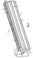
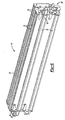
- the present invention contemplates an improved reinforcement system 10, including a carrier member 12 configured for placement within a vehicle structural member, e.g. within a cavity of the structural member.
- the carrier may include one or more cavities 16 extending the length of the carrier.
- the carrier includes one or more applications of activatable material 18 placed thereover.
- the present invention further contemplates a feature 20 for locating the carrier member 12 to the structural member 14.
- this locating feature is configured to matingly engage with the carrier member and includes one or more members (e.g. fasteners 22) for placement within apertures 23 or other corresponding recesses defined in the structural member.
- the locating feature is further configured for attachment to an end portion of the carrier member and more particularly engages one or more cavities and/or opening 16 formed through the carrier.
- the locating feature is shaped and/or sized for spacing the carrier away from the walls of the structure being reinforced to allow passage of fluids such as e-coat.
- the present invention also contemplates restrictive features, such as restrictors 24, for quick and inexpensive placement and/or locating of the activatable material 18 onto carrier member 12, without the necessary use of fasteners.
- the carrier member, activatable material or both may be formed with one or more of these features.
- other features, such as end caps 20, may also include one or more of these restrictive features.
- the reinforcing system includes a carrier adapted for placement within a hollow cavity of a structural member.
- the carrier is preferably configured to extend along an axis and includes at least a first end and a second end which reside on opposite ends of the axis.
- the carrier may also include one or more hollow cavities which extend along the length or axis of the carrier.
- the carrier can be straight or contoured along its length.
- the carrier is formed of one or more walls that extend along the length of the carrier, which may be joined or otherwise integrated together.
- the carrier may have separate pieces that are separately made and then assembled together, it may be integrally formed, or both.
- the one or more of the walls may be internal walls located substantially within exterior walls of the carrier.
- the carrier upon joining of the walls, forms one or more (or a plurality) of cavities (e.g., 1, 2, 3, 4, 5, 6 or more cavities) that extends along at least a portion of the length of the carrier and more preferably the entire length. It is contemplated that the one or more cavities may form openings extending through the carrier between the first and second ends of the carrier, thereby allowing the passage of fluids or other components through the carrier.
- the carrier 12 may be formed of a plurality of walls 26 which extend both internal and external to the carrier and along the length thereof to form a plurality of cavities.
- the carrier includes a first cavity 16A, second cavity 16B, third cavity 16C and fourth cavity 16D.
- first cavity 16A, second cavity 16B, third cavity 16C and fourth cavity 16D are contemplated.
- one or more of the walls 26 of the carrier 12 may be located adjacent an interior wall 30 of the structural member 14 in which it is placed.
- the cross-sectional profile of the carrier, as defined by the walls 26, or otherwise may correspond to the cross-sectional opening formed by the interior walls of the structural member. Accordingly, four or more walls may be located adjacent the interior structural members.
- the carrier may include one or more through holes 32 formed in the walls of the carrier.
- the through holes may provide reduced weight of the carrier.
- the through holes may also be used to directly control any flow of the activatable material, or otherwise.
- the through holes may be used to engage locating features 20 for locating the carrier within the structural member.
- the carrier may be formed of any of a variety of materials and can be formed of a single material or multiple materials.
- the carrier may be formed of polymeric materials (e.g., thermoplastics such as polyamide), metals (e.g., aluminum, steel, magnesium, metal alloys) combinations thereof or the like.
- the technique for forming and shaping the carrier will typically depend upon the material of the carrier. Examples of techniques include, without limitation, molding (e.g., injection, compression or blow molded), stamping, hydroforming, extruding or otherwise. Examples of suitable materials and forming processes can be found in commonly owned U.S. Patent No. 6,467,834, to Barz et al. , the entire contents of which are herein incorporated by reference for all purposes.
- the system 10 includes an activatable material 18 configured for providing structural reinforcement properties upon activation and curing thereof.
- the carrier includes activatable material located over the carrier.
- the activatable material may comprise an adhesive material, or otherwise includes adhesive qualities, for bonding to the carrier and structural member upon activation thereof.
- the activatable material is restrictively placed over the carrier (via restrictor 24 or otherwise) such that movement of the activatable material is limited or substantially limited with respect to the carrier.
- the activatable material, the restrictors, or both may be elastically or plastically deformable for placement of the activatable material within one or more restrictive features, between restrictive features or otherwise such that the configuration of the restrictive features and/or activatable material limits or substantially limits movement of the activatable material with respect to the carrier.
- the activatable material may be an expandable or foamable material that is activated (e.g. by heat, moisture, radiation, chemical reaction or otherwise) to expand and then cure to form a strong bond between adjacent surfaces (e.g. attachment surfaces of the carrier and structural member or otherwise).
- the activatable material is formed of a high compressive strength heat activated reinforcement material having foamable characteristics.
- the activatable material may be particularly suited for vibrational dampening for stability to the structural member, reduce acoustic noise through the structural material or both.
- the material may be generally dry to the touch or tacky and can be placed upon surfaces of members in any form of desired pattern, placement, or thickness, but is preferably a substantially uniform thickness.
- a preferred heat activated material is an expandable plastic, and preferably one that is foamable.
- a particularly preferred material is an epoxy-based structural foam.
- the structural foam may be an epoxy-based material, including an ethylene copolymer or terpolymer that may possess an alpha-olefin.
- activatable materials can be found in commonly owned U.S. Patent No. 6,846,559 , 6,941,719 and 6,921,130 , herein entirely incorporated for all purposes.
- one exemplary expandable material is L-5204 structural foam available through L&L Products, Inc. of Romeo, Michigan.
- An example of a preferred structural foam formulation for the adhesive material is an epoxy-based material that is commercially available from L&L Products of Romeo, Michigan, under the designations L5206, L5207, L5208, L5209, L-5220, L-7102, L-7220, XP321 and XP721 or others.
- the preferred materials can be processed by injection molding, extrusion compression molding or with a mini-applicator, for example according to the teaching of U.S. Patent No. 7,048,019 and 5,358,397 herein entirely incorporated by reference for all purposes. This enables the formation and creation of part designs that exceed the capability of most prior art materials.
- the activatable material in its uncured state generally is dry or relatively free of tack to the touch.
- the activatable materials may be applied to the attachment surfaces of the carrier members and/or connectors (e.g. end caps or otherwise) before or after assembly of those components together.
- preformed patterns may also be employed such as those made by extruding a sheet (having a flat or contoured surface) and then die cutting it according to a predetermined configuration in accordance with the chosen structure, panel or beam, and applying it thereto.
- the activatable material may be a heat activated, thermally expanding material.
- the material may become reactive at higher processing temperatures, such as those encountered in an automobile assembly plant, when the material is processed along with the automobile components at elevated temperatures or at higher applied energy levels, e.g., during painting preparation steps. While temperatures encountered in an automobile assembly operation may be in the range of about 148.89° C to 204.44°C (about 300°F to 400°F), body and paint shop applications are commonly about 93.33°C (about 200°F) or slightly higher. If needed, blowing agent activators can be incorporated into the composition to cause expansion at different temperatures outside the above ranges.
- exemplary activatable materials can include combinations of two or more of the following: epoxy resin, polystyrene, styrene butadiene-styrene (SBS) block copolymer, butadiene acrylo-nitrile rubber, amorphous silica, glass microspheres, azodicarbonamide, urea, dicyandiamide. See also , U.S. Patent Nos. 6,649,243 , 6,519,854 , 6,387,470 , 6,546,693 , 6,332,737 , and 6,003,274 . [SAC to provide these Sika patent numbers. This should cover their acoustical foams and patented composition just took out in the EPO opposition]
- the activatable material 18 is located adjacent to the exterior portion of the carrier 12, and may be in contact therewith or spaced therefrom. Preferably, the activatable material remains proximate to the carrier during placement within the structural member 14 or otherwise.
- the activatable material, carrier or both may include a restrictive feature for locating the activatable material proximate to the carrier. Preferably, the restrictive feature also limits or substantially limits movement of the activatable material with respect to the carrier.
- the activatable material may also be placed on or with other components associated with the carrier, such as end caps, or otherwise.
- the activatable material is restrictively located onto the carrier to limit or substantially limited movement of the material with respect to the carrier.
- placing and locating of the activatable material relative to the carrier may be performed without the use of fasteners.
- the restrictive placement of the activatable material is achieved through restrictors 24 placed or formed with the carrier, activatable material, or both.
- the one or more restrictors 24 may be placed or formed upon one or more wall portions of the carrier. This may include opposing wall portions, four generally outwardly facing wall portions (for example, two opposite walls generally perpendicular to two other opposite walls), or otherwise. Preferably, the restrictors are located on an exterior portion of the carrier. More preferably, the restrictors are located adjacent the wall portions defining the structural member when the carrier is placed therein. The restrictors may be located on 1, 2, 3, 4 or more walls, including substantially all of the walls forming the carrier or extending along the axis of the carrier.
- the restrictor comprises or includes a slotted portion 34 that extends along the length carrier wall.
- the slotted portion includes a cross-sectional open area comprising generally of a rectangle having a width and height. However, other shapes are contemplated including circular, elliptical, square, triangle, or otherwise.
- the cross-sectional open area may be generally consistent through the length of the carrier.
- the slotted portion may also include an opening or groove 36 which extends along the length of the carrier. The groove is located on an outer portion of the carrier for receiving the activatable material or allowing the activatable material to exit the slotted portion during activation thereof.
- the activatable material may have a cross-sectional shape corresponding to the cross-sectional shape of the slotted portion.
- the activatable material may extend along substantially all or a portion of the slotted portion and may comprise a strip or other configuration. In one configuration, the activatable material may be inserted into the end of the slotted portion. Alternatively, the activatable material may be snapped into the slotted portion, via the groove extending along the slotted portion. Either way, or otherwise, a friction fit may be created between the slotted portion and the activatable material to prevent the activatable material from exiting therefrom.
- the carrier may include one or more stops 38 for preventing or limiting movement of the activatable material within slotted portion.
- the stops may be integrally formed with the carrier or separately formed.
- the stops comprise one or more pins or clips that extending through an opening formed in the slotted portion of the carrier. By extending into the slotted portion the pins or clips prevent or limit movement of the activatable material along the slotted portion.
- the restrictor comprises or includes one or more features extending from the carrier, activatable material, or both, adapted to limit movement of the activatable material in at least one direction.
- the restrictors may be separately formed and attached to the carrier or may be integrally formed with the carrier to form a unitary structure, as with all restrictor configurations described herein.
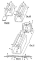
- the restrictors comprise one or more, and preferably opposing members extending from the carrier, each forming a cavity and/or opening for receiving the activatable material and forming an end stop 40 for limiting movement of the activatable material parallel to the carrier axis, perpendicular to the carrier axis, or both.
- the stops may be configured to prevent the material from moving therepast, either prior to, during or after activation of the activatable material.
- the stops may be configured to prevent movement along the axis of the carrier but allow movement in a direction non-parallel to the carrier axis.
- the stops may be configured to allow parallel movement with respect to the carrier axis but prevent non-parallel movement.
- the one or more end stops may include one or more tabs, protections, or otherwise, 42 configured to prevent movement of the activatable material perpendicular to the axis of the carrier.
- the restrictors are formed of a raised portion extending from one of the carrier walls.
- the restrictor includes a top wall and sidewalls joining the top wall to the carrier wall, wherein each of the restrictors forms a cavity and includes an opening extending in the direction of an opposing restrictor.
- the cavities and/or openings, as with each of the restrictors described herein, may include a cross-sectional shape generally corresponding to a portion of the activatable material.
- the restrictors may be formed of a turned up portion of the carrier wall that extends outwardly from the carrier wall and back towards an opposing restrictor to form at least a portion of a cavity and opening extending towards the opposing restrictor.
- the restrictors include sides wall tabs 42 extending from the carrier wall for limiting or preventing lateral movement of the activatable material.
- the restrictive features may include one or more intermediate restrictors, e.g. tabs, projections, recess, opening, or otherwise, 44 located between the restrictor end stops for preventing movement generally perpendicular to a line extending between the end stops.
- the intermediate stop includes two generally adjacent tabs or stops having oppositely facing openings.
- the restrictors extend from the carrier wall and generally back towards the opposing intermediate restrictor.
- the oppositely facing openings formed by the intermediate restrictors allow a strip of activatable material 46 to be placed between the intermediate restrictors and rotated into the openings thereby substantially preventing the strip of activatable material to move away from the walls of the carrier.
- the intermediate restrictor comprises one or more openings formed through the carrier members for receiving a strip of activatable material and preventing perpendicular movement with respect to the carrier axis.
- the strip of activatable material may be plastically and/or elastically deformed such that the end portions can be placed into openings formed by the end stop restrictors, as shown in Fig. 8D .
- the restrictor comprises or includes one or more engagement features 48 located with the reinforcement material and configured to engage one or more corresponding engagement features 50 located with the carrier.
- the engagement features may be integrally formed or formed separate from the reinforcement material and carrier.
- the engagement features comprise a protrusion extending from the activatable material configured to engage an opening formed in the carrier.
- one or more stops 38 may be further used to limit or substantially limit movement of the activatable material, carrier, or both, such that the engagement features do not disengage.
- the activatable material may be placed over a portion of an end cap 20 which is configured for engagement with a carrier.
- the material may be located externally or internally to the carrier upon attachment of the end cap to the carrier.
- the end cap is configured with one or more projections 52 adapted to fit within the cavities or openings formed in the carrier.
- one or more of the projections include activatable material located thereover.
- the activatable material may also comprise, or otherwise include, an adhesive material configured for bonding to one or more inner portions of the carrier, prior to, during or after activation of the activatable material.
- the adhesive may comprise a portion of the activatable material or may be applied over the activatable material.
- the carrier may include one or more locators for locating the carrier within structural member and maintaining the position of the carrier.
- locators may be integrally formed with the carrier or comprise a separate feature which engages the carrier and structural member.
- Suitable locators features include protrusions, extensions, tabs, springs, mechanical fasteners (e.g. threaded fasteners, hook and latch, snap fittings, Christmas tree clips, or otherwise).
- Other locators include non-mechanical fasteners (e.g. friction fittings, adhesives, or otherwise).
- the locators may be formed or placed about portions of the carrier. However, in one configuration at least one locator is at the first end of the carrier and at least one locator is at the second end. Thus it is possible to generally orientate the axis of the carrier with the axis of the structural cavity.
- the system can include one or more end caps 20 for placement at the first end, second end, or both ends, of the carrier.
- the one or more end caps may be configured with one or more features for improving reinforcement of the end cap, structural member or both. Such improvement may comprise positioning of the carrier within the structural member prior to activation of the activatable material, controlling or preventing flow of the activatable material during activation, strengthening of the reinforcement system, structural member, or otherwise.
- the end caps may be configured as a sound baffle for inhibiting the transfer of sound, noise, vibration, or the like, along the structural member.
- the end caps may include an outer portion or walls having a corresponding shape to the interior wall of the structural member.
- the outer portion or wall of the end cap may substantially or entirely span the opening formed by the structural member in which the carrier and/or end cap is placed in.
- the end caps may be configured to extend along at least a portion of an axis of the structural member cavity.
- the end caps may include a length equal to at least about 2%, 5%, 10%, 25% or more of the length of the carrier member.
- the combination of the outer portion or walls and length, the end caps may comprise a stand alone reinforcement member in of itself. Accordingly, the end caps may comprise a sound baffle member, reinforcement member or both such as bulkhead.
- the outer portion or walls of the end caps may include activatable material, as discussed herein, for attachment and/or sealing of the end cap to the structural member.
- the activatable material may help to inhibit the transferring of sound, noise vibration or otherwise.
- the activatable material may further reinforce the structural member.
- the Activatable material may extend along the outer portion or wall of the end cap, along an end portion of the cap, both, or otherwise.
- the end caps 20 of the present invention may be configured to cover all or a portion of the openings formed through the carrier, which may control, limit or prevent all or a portion of the activatable material from entering or leaving the cavity of the carrier.
- the end caps may be placed at the first end, second end or both ends of the carrier.
- the end caps may be configured for engagement with the interior surface, exterior surface or both surfaces of the carrier walls. It is contemplated that the engagement of the end caps with the carrier may comprise a friction fit. In one configuration, the friction fit may comprise a friction fit formed between one or more projections 52 and/or activatable material 18 and the interior walls forming a cavity of the carrier. Of course, it is contemplated that the friction fit may be formed with an outwardly extending ring or lip 54 which extends about at least a portion of the end caps and configured for forming a friction fit with the exterior (or interior) walls of the carrier.
- the engagement of the end cap may be further improved through the use of an attachment feature for attaching the end caps to the carrier.
- Suitable attachment features include fiction fit, adhesives, fasteners, snap fittings, hook and latch, combinations thereof, or otherwise.
- the end caps and the carrier may include corresponding portions of an attachment feature.
- the attachment feature may comprise a snap fitting 56 configured for engaging a corresponding component located on or with the carrier.
- the snap fitting may comprise one or more projections 58 extending away from the end cap.
- the projections may include a lip, latch, flange, or the like, 60 which is configured to engage an opening, recess, groove, or the like, 62 of the carrier.
- the attachment feature may comprise a fastener (such as a screw, clip, or otherwise) adapted to extend through openings formed in the carrier, end caps, or both, in order to attach the same.
- the end caps may be configured with one or more locators 64 for locating the end caps, and hence the carrier, with respect to an interior portion of the structural member.
- the locator may comprise a portion or the end cap or a separate component.
- the end cap included an integrally formed locator configured to engage a corresponding component of the structural member.
- the locator may comprise a separate component configured for engagement with both the end cap and the structural member.
- the end caps and locators locate the carrier such that the amount of contact between the carrier, end cap, activatable material, or combinations thereof and the structural member is minimized.
- the structural members may be subjected to anti-corrosion treatments (such as e-coating, or otherwise) for assisting in the prevention of corrosion.
- anti-corrosion treatments such as e-coating, or otherwise
- Suitable locators include fasteners such as clips (e.g. a 'Christmas tree' shaped clip), or the like.
- the end caps may also be configured for controlling the activatable material from entering or leaving the carrier cavity.
- the end caps may cover all or a portion of the openings formed through the carrier by the one or more cavities.
- the end caps may include one or more openings 66 for allowing fluid (e.g. activating material, e-coating for the structural member, or otherwise) to flow therethough.
- the end cap may include one or more reinforcement features integrally formed, or attached thereto, for providing additional support to the end caps, carrier, or both.
- the additional support may provide resistance to lateral forces with respect to the axis of the carrier, or otherwise.
- the reinforcement feature may comprise one or more internally formed ribs 68. In the configurations show, the ribs are formed within the projections extending from the end caps which are adapted for insertion and attachment to the carrier.
- the end caps may be configured to provide additional reinforcement of the carrier by inserting one or more projections, ribs, or both, which are configured for attachment to an internal portion of the carrier, through adhesive and/or activatable material, such that additional support against lateral forces, or otherwise, is provided.
- Other reinforcement configurations are contemplated.
- the end caps may be configured to limit movement of the activatable material placed on the carrier.
- the end caps may include an outwardly extending flange or lip 70 which extends to or beyond the outer circumference of the carrier walls. In doing so, restrictively place material on the outer or interior portion of the carrier may be prevented from moving beyond the end cap and end portion of the carrier.
- end caps may be alternatively attached directly to an end portion of a structural member (as oppose to the carrier), as described herein, to provide reinforcement of the structural member, limit flow of any expandable material located within or external to the structural member, or otherwise.
- the end caps may be formed of any suitable material including metal, plastic, rubber, ceramic, or otherwise. However, in one preferred configuration, the end caps are formed of a lightweight material such as a plastic and more preferable a thermoplastic or thermoset plastic. The material of the end caps may be the same as the carrier or different. It is contemplated, as described herein, that the end cap may be integrally formed with the carrier through a molding process, such as blow molding, rotational molding or otherwise.
- the reinforcing system of the present invention may be used in a variety of applications which includes a structural member and which may benefit from reinforcement thereof.
- the system may be used in the vehicular industry for reinforcing structural systems thereof to form a reinforced structural member.
- any of the systems herein can be placed in a structural member and activated to form the reinforced structural member.
- the system may be used to reinforce various structural members of a vehicle including frame, frame rails, rockers, pillars, roof members, or otherwise.
- the structural member may comprise one or more frame components (such as tubular frame members or otherwise) extending the length of a vehicle and/or other frame members located therebetween (e.g. rocker frame members).
- the system may be used to reinforce a frame rail, rocker, or the like depending on the type of frame (e.g. unibody, etc.).
Landscapes
- Engineering & Computer Science (AREA)
- Mechanical Engineering (AREA)
- Chemical & Material Sciences (AREA)
- Combustion & Propulsion (AREA)
- Transportation (AREA)
- Architecture (AREA)
- Structural Engineering (AREA)
- Physics & Mathematics (AREA)
- Acoustics & Sound (AREA)
- Connection Of Plates (AREA)
- Body Structure For Vehicles (AREA)
- Orthopedics, Nursing, And Contraception (AREA)
- Reinforcement Elements For Buildings (AREA)
- Civil Engineering (AREA)
Claims (15)
- Verstärkungssystem (10) für ein Strukturelement, wobei das System umfasst:ein Trägerelement mit einer sich zwischen einem ersten Ende und einem zweiten Ende erstreckenden Länge, wobei das Trägerelement eine oder mehr Trägerwände aufweist, die miteinander derart verbunden sind, dass sie eine Mehrzahl von Kavitäten (16) bilden, die sich entlang der Länge des Trägers erstrecken, wobei der Träger eine Querschnittsform aufweist, die ungefähr der Querschnittsform von Innenwänden eines hohlen Strukturelements entspricht;ein aktivierbares Material (18), das über dem Träger angeordnet ist und derart konfiguriert ist, dass es sich nach Anwendung von Hitze ausdehnt und an den Innenwänden des hohlen Strukturelements haftet, um diese zu verstärken; undein oder mehr einschränkende Elemente (24), die auf dem Trägerelement angeordnet oder mit diesem integriert sind, wobei die ein oder mehr einschränkenden Elemente derart konfiguriert sind, dass sie das aktivierbare Material empfangen und Bewegungen des aktivierbaren Materials bezüglich des Trägers einschränken, dadurch gekennzeichnet, dass es zwei Kavitäten aufweist, die auf entgegengesetzten Enden des Trägerelements angeordnet sind und Öffnungen bilden, die sich aufeinanderzu erstrecken, wobei die Öffnungen eine Querschnittsform haben, die ungefähr einem Bereich des aktivierbaren Materials vor der Aktivierung entsprechen, wobei die Kavitäten aus einem erhöhten Bereich einer der Trägerseitenwände gebildet sind und eine obere Wand (40) und Seitenwände (42) aufweisen, die mit dem Träger in einem Stück gebildet sind, um eine einheitliche Struktur zu bilden.
- Verstärkungssystem nach Anspruch 1, wobei die Kavitäten Bewegungen des aktivierbaren Materials in einer Richtung parallel zu einer Achse des Trägers und in einer Richtung senkrecht zu der Achse einschränken.
- Verstärkungssystem nach Anspruch 1 oder Anspruch 2, wobei die Kavitäten jeweils aus einem nach oben gewandten Bereich gebildet sind, der sich von einer der Trägerseitenwände nach außen und allgemein zurück aufeinanderzu erstreckt, wobei jede der Kavitäten weiter nach oben gewandte Seitenbereiche aufweist, die sich von der genannten einen der Trägerseitenwände nach außen erstrecken, wobei die nach oben gewandten Bereiche mit dem Träger in einem Stück gebildet sind, um eine einheitliche Struktur zu bilden.
- Verstärkungssystem nach einem der vorhergehenden Ansprüche, wobei die ein oder mehr einschränkenden Elemente weiter ein dazwischenliegendes Zurückhalteelement (44) aufweisen, das zwischen den auf entgegengesetzten Enden des Trägerelements gebildeten Kavitäten angeordnet ist und in einem Stück mit dem Trägerelement gebildet ist, um eine einheitliche Struktur zu bilden, wobei das dazwischenliegende einschränkende Element einen Lappen aufweist, der sich allgemein nach außen und parallel zu der Trägeroberfläche erstreckt, um eine Öffnung zur Aufnahme des aktivierbaren Materials zu bilden.
- Verstärkungssystem nach einem der vorhergehenden Ansprüche, wobei die ein oder mehr einschränkenden Elemente zwei dazwischenliegende Zurückhalteelemente aufweisen, wobei die zwei Zurückhalteelemente bezüglich einer Trägerachse axial versetzt sind und in entgegengesetzte Richtungen ausgerichtet sind, so dass sich die von den dazwischenliegenden Zurückhalteelementen gebildeten Öffnungen allgemein aufeinanderzu erstrecken.
- Verstärkungssystem nach einem der vorhergehenden Ansprüche, wobei die ein oder mehr einschränkenden Elemente eine Aussparung (34) aufweisen, die sich entlang der Länge des Trägerelements erstreckt, wobei die Aussparung mit dem Trägerelement gebildet ist, um eine einheitliche Struktur zu bilden, und eine Öffnung aufweist, die einer Form von zumindest einem Bereich des aktivierbaren Materials entspricht, um Bewegungen des aktivierbaren Materials in einer Richtung senkrecht zu einer Trägerachse einzuschränken.
- Verstärkungssystem nach Anspruch 6, wobei die ein oder mehr einschränkenden Elemente weiter ein oder mehr Anschlagstücke (38) aufweisen, die sich in die Aussparung hinein erstrecken, um Bewegungen des aktivierbaren Materials in einer Richtung parallel zu der Trägerachse einzuschränken.
- Verstärkungssystem nach Anspruch 7, wobei das Anschlagsstück durch eine Endkappe (20) gebildet ist, welche den Endbereich des Trägerelementes passgenau erfasst.
- Verstärkungssystem nach einem der vorhergehenden Ansprüche, weiter umfassend eine oder mehr Endkappen, die an dem ersten oder zweiten Ende oder an beiden Enden des Trägers angeordnet sind, wobei die ein oder mehr Endkappen zum Erfassen des Endbereichs des Trägers konfiguriert sind.
- Verstärkungssystem nach einem der vorhergehenden Ansprüche, weiter umfassend ein oder mehr Befestigungselemente (22) zum Befestigen des Trägerelements an den Innenwänden des hohlen Strukturelements, wobei die ein oder mehr Befestigungselemente auf oder mit den ein oder mehr Kappen angeordnet sind.
- Verstärkungssystem nach einem der vorhergehenden Ansprüche, wobei die ein oder mehr einschränkenden Elemente eine oder mehr Öffnungen aufweisen, die durch eine der einen oder mehr Seitenwände gebildet sind, die so geformt sind, dass sie gleitbar einen Finger (48) erfassen, der auf dem aktivierbaren Material gebildet ist.
- Verstärkungssystem nach einem der vorhergehenden Ansprüche, wobei die ein oder mehr Einschränkungselemente weiter ein oder mehr Anschlagstücke (38) aufweisen, welche die Bewegung des aktivierbaren Elements nach einem Erfassen zwischen den ein oder mehr Öffnungen und dem Finger einschränken.
- Verstärkungssystem nach einem der vorhergehenden Ansprüche, wobei die Mehrzahl von Kavitäten aufeinanderfolgend entlang einer Höhe oder Breite des Trägers angeordnet sind.
- Verstärkungssystem nach einem der Ansprüche 8 bis 13, wobei die Endkappe einen Schalldämpfer aufweist.
- Verstärkungssystem nach einem der Ansprüche 8 bis 13, wobei die Endkappe ein Verstärkungselement aufweist.
Applications Claiming Priority (3)
| Application Number | Priority Date | Filing Date | Title |
|---|---|---|---|
| US82029506P | 2006-07-25 | 2006-07-25 | |
| US11/781,587 US7913467B2 (en) | 2006-07-25 | 2007-07-23 | Structural reinforcements |
| PCT/US2007/074205 WO2008014250A1 (en) | 2006-07-25 | 2007-07-24 | Structural reinforcements |
Publications (2)
| Publication Number | Publication Date |
|---|---|
| EP2043903A2 EP2043903A2 (de) | 2009-04-08 |
| EP2043903B1 true EP2043903B1 (de) | 2011-10-05 |
Family
ID=38698769
Family Applications (1)
| Application Number | Title | Priority Date | Filing Date |
|---|---|---|---|
| EP07840488A Active EP2043903B1 (de) | 2006-07-25 | 2007-07-24 | Strukturelle verstärkungen |
Country Status (6)
| Country | Link |
|---|---|
| US (6) | US7913467B2 (de) |
| EP (1) | EP2043903B1 (de) |
| JP (1) | JP5384340B2 (de) |
| KR (1) | KR20090048574A (de) |
| AT (1) | ATE527161T1 (de) |
| WO (1) | WO2008014250A1 (de) |
Cited By (1)
| Publication number | Priority date | Publication date | Assignee | Title |
|---|---|---|---|---|
| EP3486146B1 (de) | 2017-11-15 | 2021-04-14 | Sika Technology Ag | Vorrichtung zur verstärkung und abdichtung eines strukturelementes |
Families Citing this family (56)
| Publication number | Priority date | Publication date | Assignee | Title |
|---|---|---|---|---|
| US7913467B2 (en) | 2006-07-25 | 2011-03-29 | Zephyros, Inc. | Structural reinforcements |
| WO2008080415A1 (en) * | 2006-12-28 | 2008-07-10 | Henkel Ag & Co. Kgaa | Acoustic baffle |
| US7735906B2 (en) * | 2007-09-28 | 2010-06-15 | Zephyros, Inc. | Reinforcement system for an automotive vehicle |
| US8020924B2 (en) * | 2007-12-26 | 2011-09-20 | Sika Technology Ag | Integrated reinforcing crossmember |
| US8293360B2 (en) * | 2008-02-27 | 2012-10-23 | Sika Technology Ag | Baffle |
| US8133929B2 (en) * | 2008-04-15 | 2012-03-13 | Sika Technology Ag | Method for incorporating long glass fibers into epoxy-based reinforcing resins |
| ES2579228T3 (es) | 2008-07-25 | 2016-08-08 | Sika Technology Ag | Capas de espuma o adhesivo interconectadas |
| EP2154052A1 (de) | 2008-08-12 | 2010-02-17 | Sika Technology AG | Strukturiertes Verstärkungssystem |
| US9097000B2 (en) | 2008-10-03 | 2015-08-04 | Thomas M. Espinosa | Hold down system using hollow bearing members |
| BRPI0921447B8 (pt) | 2008-11-07 | 2020-12-08 | Zephyros Inc | estrutura de reforço híbrido |
| EP2251250A1 (de) | 2009-05-05 | 2010-11-17 | Sika Technology AG | Bindung mit Klebewulsten oder -höckern |
| US8046858B2 (en) * | 2009-09-02 | 2011-11-01 | Safe Rack Llc | Gangway handrail and method for manufacturing the same |
| TWM379482U (en) * | 2009-12-22 | 2010-05-01 | Hiwin Mikrosystem Corp | Rigid cross-beam for gantry crane |
| US9259867B2 (en) * | 2010-05-21 | 2016-02-16 | Zephyros, Inc. | Method and device for application of structural materials |
| JP2012111103A (ja) * | 2010-11-24 | 2012-06-14 | Hitachi Chemical Co Ltd | シートモールディングコンパウンド(smc)成形品と金具を接着する方法 |
| EP2497700A1 (de) * | 2011-03-11 | 2012-09-12 | Sika Technology AG | Verstärkte Panelstruktur |
| CN103857511B (zh) | 2011-06-17 | 2016-01-20 | 泽菲罗斯公司 | 腔体密封组件 |
| US8833839B2 (en) | 2012-04-13 | 2014-09-16 | Toyota Motor Engineering & Manufacturing North America, Inc. | Impact protection structures for vehicles |
| US8608230B2 (en) * | 2012-04-13 | 2013-12-17 | Toyota Motor Engineering & Manufacturing North America, Inc. | Localized energy dissipation structures for vehicles |
| GB201207481D0 (en) | 2012-04-26 | 2012-06-13 | Zephyros Inc | Applying flowable materials to synthetic substrates |
| US8926005B2 (en) | 2012-05-24 | 2015-01-06 | Zephyros, Inc. | Vehicle body structure cut zones |
| EP3483046A1 (de) * | 2012-06-08 | 2019-05-15 | Zephyros Inc. | Trennwand mit expandierendem material |
| EP3269621B1 (de) * | 2012-11-14 | 2019-08-07 | Zephyros Inc. | Expandierende plattenversteifung |
| EP3063053B1 (de) | 2013-10-31 | 2020-02-12 | Sika Technology AG | Sperre oder verstärkungselement zum abdichten und/oder verstärken eines hohlraumes und verfahren zur herstellung einer solchen sperre oder eines solchen verstärkungselements |
| CN103912554A (zh) * | 2013-11-12 | 2014-07-09 | 芜湖长启炉业有限公司 | 双头发泡铝用型材端盖 |
| CN103912555A (zh) * | 2013-11-12 | 2014-07-09 | 芜湖长启炉业有限公司 | 十字形铝型材封头 |
| CN103912784A (zh) * | 2013-11-12 | 2014-07-09 | 芜湖长启炉业有限公司 | 品形型材封盖 |
| JP6152790B2 (ja) * | 2013-12-05 | 2017-06-28 | マツダ株式会社 | 車両のシートバックバー構造 |
| CN103741880B (zh) * | 2013-12-27 | 2016-02-10 | 陈星耕 | 集成房屋拼装式柱状型材组件 |
| US11198236B2 (en) | 2014-11-14 | 2021-12-14 | Zephyros, Inc. | Multi-shot injection molded method and product |
| US9764769B2 (en) * | 2015-02-09 | 2017-09-19 | Honda Motor Co., Ltd. | Vehicle frame structural member assembly and method |
| BR112017024381A2 (pt) | 2015-05-14 | 2018-07-24 | Zephyros Inc | dispositivo |
| DE102015210485A1 (de) * | 2015-06-09 | 2016-12-15 | Bayerische Motoren Werke Aktiengesellschaft | Kraftfahrzeug |
| US10000241B2 (en) * | 2016-02-26 | 2018-06-19 | Ford Global Technologies, Llc | Rocker reinforcement bracket having anti-corrosion holes |
| US11685085B2 (en) * | 2016-04-21 | 2023-06-27 | Zephyros, Inc. | Tubular member sealing device |
| EP3263425B1 (de) | 2016-06-27 | 2020-08-12 | Sika Technology AG | Dämmelement |
| EP3583161B1 (de) | 2017-02-17 | 2021-09-01 | Zephyros Inc. | Mindestens zwei carboxylsäure als treibmittel enthaltende aktivierbare polymerzusammensetzung |
| CN110603188A (zh) | 2017-04-21 | 2019-12-20 | Sika技术股份公司 | 加强元件 |
| CN110753655B (zh) | 2017-06-22 | 2022-10-28 | Sika技术股份公司 | 增强元件、增强的结构元件的系统以及用于增强结构元件的方法 |
| PL3865378T3 (pl) | 2017-06-22 | 2024-06-24 | Sika Technology Ag | Podłączenie elementów nadwozia w pojazdach mechanicznych |
| EP3710340B2 (de) | 2017-11-15 | 2025-07-16 | Sika Technology AG | System eines verstärkten strukturelements |
| EP3486147B2 (de) | 2017-11-15 | 2025-10-15 | Sika Technology Ag | System eines verstärkten strukturelements |
| EP3710341B1 (de) | 2017-11-15 | 2022-01-12 | Sika Technology AG | Vorrichtung zur verstärkung, abdichtung oder dämpfung eines strukturelementes |
| US10870978B2 (en) | 2018-03-09 | 2020-12-22 | Cetres Holdings, Llc | Reinforced stud-framed wall |
| DE102018205826A1 (de) * | 2018-04-17 | 2019-10-17 | Röchling Automotive SE & Co. KG | Kfz-Karosserie mit Rohkarosse und Fahrzeugboden sowie einem Sicherungsstrukturbauteil |
| EP4101740B1 (de) | 2018-05-23 | 2025-10-29 | Sika Technology AG | Dämmelement und verfahren zur dämmung eines strukturelements |
| DE102018129396A1 (de) * | 2018-11-22 | 2020-05-28 | Benteler Automobiltechnik Gmbh | Träger mit wenigstens einer Hohlkammer |
| EP3666617B1 (de) | 2018-11-22 | 2022-09-28 | Bombardier Transportation GmbH | Doppelwandige hüllstruktur für einen wagenkasten |
| US12043021B2 (en) | 2019-09-27 | 2024-07-23 | Zephyros, Inc. | Room temperature foamed and cured carriers |
| EP4087732A1 (de) | 2020-01-10 | 2022-11-16 | Zephyros Inc. | Verstärkung für einen seitenaufprall |
| WO2022162058A1 (en) | 2021-01-27 | 2022-08-04 | Zephyros, Inc. | Low odor heat-expandable materials |
| US12497828B2 (en) | 2023-08-04 | 2025-12-16 | Patio Designs, Llc | Structural beam assembly |
| EP4523999A1 (de) | 2023-09-13 | 2025-03-19 | Sika Technology AG | Verstärkungselement mit endkappe |
| US20250163707A1 (en) * | 2023-11-21 | 2025-05-22 | Mikhail Kuzmenko | Deck Board End Cap Device |
| WO2025210157A1 (en) | 2024-04-03 | 2025-10-09 | Sika Technology Ag | Reinforcer |
| CN118439097B (zh) * | 2024-07-11 | 2024-10-22 | 扬州众如金属制品有限公司 | 一种车架纵梁加强结构 |
Family Cites Families (122)
| Publication number | Priority date | Publication date | Assignee | Title |
|---|---|---|---|---|
| US1975006A (en) * | 1932-03-09 | 1934-09-25 | Kingsbury Machine Tool Corp | Indexing and control mechanism for independent metal working units |
| US2409209A (en) * | 1944-07-25 | 1946-10-15 | Elastic Stop Nut Corp | Removable basket nut |
| US3259165A (en) * | 1964-07-14 | 1966-07-05 | Vsi Corp | Floating nut retainer assembly |
| US3813071A (en) * | 1972-04-12 | 1974-05-28 | N Noryd | Fastener assembly for handrails |
| US3987904A (en) * | 1974-08-15 | 1976-10-26 | Height Frank S | Storage of articles |
| DE2937454C2 (de) * | 1979-09-15 | 1985-08-08 | SCHÜCO Heinz Schürmann GmbH & Co, 4800 Bielefeld | Verbundprofil, insbesondere für Fenster, Türen und Fassaden sowie Verfahren zum Herstellen des Verbundprofils |
| JPS57117542A (en) | 1981-01-13 | 1982-07-22 | Nitto Electric Ind Co Ltd | Molded article of expandable resin |
| US4400105A (en) * | 1981-10-16 | 1983-08-23 | Printck, Inc. | Computer printer paper tractor mounting means |
| US4488844A (en) * | 1982-06-07 | 1984-12-18 | Jacobson Mfg. Co., Inc. | Floating fastener retainer assembly with removable fasteners |
| US4463870A (en) * | 1983-10-19 | 1984-08-07 | L & L Products, Inc. | Closure plate for an opening |
| JPS6258243U (de) * | 1985-10-01 | 1987-04-10 | ||
| US4790701A (en) * | 1987-05-08 | 1988-12-13 | Jacobson Mfg. Co., Inc. | Floating fastener retainer assembly with removable fasteners |
| US4861097A (en) | 1987-09-18 | 1989-08-29 | Essex Composite Systems | Lightweight composite automotive door beam and method of manufacturing same |
| US5213391A (en) * | 1990-10-25 | 1993-05-25 | Nissan Motor Co., Ltd. | Body skeleton element of vehicle and manufacturing method thereof |
| JPH0772233B2 (ja) | 1991-02-19 | 1995-08-02 | 日本ゼオン株式会社 | エポキシ樹脂系発泡性組成物 |
| JPH0669739B2 (ja) | 1991-06-11 | 1994-09-07 | 日本ゼオン株式会社 | パネル補強用シート材料及びそれを用いた車輌外板パネル構造体 |
| US5358397A (en) | 1993-05-10 | 1994-10-25 | L&L Products, Inc. | Apparatus for extruding flowable materials |
| US5506025A (en) | 1995-01-09 | 1996-04-09 | Sika Corporation | Expandable baffle apparatus |
| JP3954119B2 (ja) | 1995-01-21 | 2007-08-08 | イイダ産業株式会社 | 加熱発泡充填補強材及び同加熱発泡充填補強材を用いた閉断面構造部材補強構造 |
| JP2721327B2 (ja) * | 1995-02-09 | 1998-03-04 | 株式会社ネオックスラボ | 中空構造物における発泡性材料の支持構造 |
| US5755486A (en) | 1995-05-23 | 1998-05-26 | Novamax Technologies Holdings, Inc. | Composite structural reinforcement member |
| US6165588A (en) * | 1998-09-02 | 2000-12-26 | Henkel Corporation | Reinforcement of hollow sections using extrusions and a polymer binding layer |
| JPH094612A (ja) * | 1995-06-20 | 1997-01-07 | Matsushita Electric Works Ltd | 取付装置 |
| JP3501879B2 (ja) * | 1995-07-31 | 2004-03-02 | 株式会社ネオックスラボ | 中空構造物における発泡性材料の支持構造 |
| JP3516782B2 (ja) * | 1995-09-21 | 2004-04-05 | 株式会社ネオックスラボ | 中空構造物の中空室遮断用発泡性基材の製造方法 |
| CA2253792C (en) * | 1996-05-10 | 2001-08-21 | Henkel Kommanditgesellschaft Auf Aktien | Internal reinforcement for hollow structural elements |
| US6341467B1 (en) * | 1996-05-10 | 2002-01-29 | Henkel Corporation | Internal reinforcement for hollow structural elements |
| JPH1089545A (ja) * | 1996-09-18 | 1998-04-10 | Toosetsu Kk | 防火区画貫通部材 |
| US5922923A (en) * | 1996-09-27 | 1999-07-13 | Uop Llc | Zeolitic reforming with selective feed-species adjustment |
| JP2943735B2 (ja) * | 1996-11-13 | 1999-08-30 | 日本電気株式会社 | 取り付け具及びそれを用いた宅内機器の取り付け方法 |
| JPH10324204A (ja) * | 1997-05-23 | 1998-12-08 | Nissan Motor Co Ltd | バンパー取付構造 |
| US6068424A (en) | 1998-02-04 | 2000-05-30 | Henkel Corporation | Three dimensional composite joint reinforcement for an automotive vehicle |
| US6003274A (en) | 1998-02-13 | 1999-12-21 | Henkel Corporation | Lightweight laminate reinforcing web |
| DE19856255C1 (de) | 1998-03-20 | 2000-01-20 | Moeller Plast Gmbh | Hohlprofil mit Innenversteifung |
| EP1359004B1 (de) | 1998-03-30 | 2006-10-11 | Henkel Kommanditgesellschaft auf Aktien | Verstärkungslaminat |
| US5992923A (en) | 1998-05-27 | 1999-11-30 | Henkel Corporation | Reinforced beam assembly |
| US6146565A (en) * | 1998-07-15 | 2000-11-14 | Noble Polymers, L.L.C. | Method of forming a heat expandable acoustic baffle |
| US6247287B1 (en) * | 1998-08-05 | 2001-06-19 | Neo-Ex Lab, Inc. | Structure and method for closing and reinforcing hollow structural members |
| US6186581B1 (en) * | 1998-08-10 | 2001-02-13 | Honda Giken Kogyo Kabushiki Kaisha | End member for a hollow structural piece on a vehicle, and method of using same |
| US6387470B1 (en) | 1998-11-05 | 2002-05-14 | Sika Corporation | Sound deadening and structural reinforcement compositions and methods of using the same |
| US6235367B1 (en) * | 1998-12-31 | 2001-05-22 | Robert D. Holmes | Composite material for construction and method of making same |
| US6092864A (en) * | 1999-01-25 | 2000-07-25 | Henkel Corporation | Oven cured structural foam with designed-in sag positioning |
| US6131897A (en) * | 1999-03-16 | 2000-10-17 | L & L Products, Inc. | Structural reinforcements |
| US6176052B1 (en) * | 1999-05-21 | 2001-01-23 | Tosetz Co., Ltd. | Fire retarding division penetrating member |
| EP1196677B2 (de) * | 1999-07-15 | 2010-08-11 | SCHÜCO International GmbH & Co. | Kunststoffhohlprofil |
| KR20010049950A (ko) * | 1999-08-05 | 2001-06-15 | 제임스 이. 미러 | 차체의 프레임구조 |
| US6263635B1 (en) | 1999-12-10 | 2001-07-24 | L&L Products, Inc. | Tube reinforcement having displaceable modular components |
| US6668457B1 (en) * | 1999-12-10 | 2003-12-30 | L&L Products, Inc. | Heat-activated structural foam reinforced hydroform |
| US6644902B1 (en) * | 2000-01-11 | 2003-11-11 | E & E Manufacturing Company, Inc. | Cage-nut assembly |
| US6253524B1 (en) | 2000-01-31 | 2001-07-03 | Sika Corporation | Reinforcing member with thermally expansible structural reinforcing material and directional shelf |
| AU2001231087A1 (en) | 2000-01-31 | 2001-08-07 | Sika Corporation | Structural reinforcing member with ribbed thermally expansible foaming material |
| US6199940B1 (en) | 2000-01-31 | 2001-03-13 | Sika Corporation | Tubular structural reinforcing member with thermally expansible foaming material |
| US6305136B1 (en) * | 2000-01-31 | 2001-10-23 | Sika Corporation | Reinforcing member with beam shaped carrier and thermally expansible reinforcing material |
| CA2399457C (en) | 2000-02-11 | 2009-09-15 | L&L Products, Inc. | Structural reinforcement system for automotive vehicles |
| US6467834B1 (en) | 2000-02-11 | 2002-10-22 | L&L Products | Structural reinforcement system for automotive vehicles |
| US6482486B1 (en) * | 2000-03-14 | 2002-11-19 | L&L Products | Heat activated reinforcing sleeve |
| US6382635B1 (en) * | 2000-03-17 | 2002-05-07 | Sika Corporation | Double walled baffle |
| JP2002012167A (ja) * | 2000-04-26 | 2002-01-15 | Neoex Lab Inc | 中空構造物の補強構造とその補強具 |
| US6413611B1 (en) | 2000-05-01 | 2002-07-02 | Sika Corporation | Baffle and reinforcement assembly |
| ES2261406T3 (es) * | 2000-06-02 | 2006-11-16 | Rieter Automotive (International) Ag | Elemento de inserto para el cierre hermetico de una cavidad. |
| JP2002035743A (ja) * | 2000-07-21 | 2002-02-05 | Kurita Water Ind Ltd | 軟水装置 |
| JP3643019B2 (ja) * | 2000-07-24 | 2005-04-27 | 共和産業株式会社 | 中空室遮断具及び中空室遮断方法 |
| US6494525B1 (en) | 2000-09-15 | 2002-12-17 | Sika Corporation | Side impact reinforcement |
| US6471285B1 (en) * | 2000-09-29 | 2002-10-29 | L&L Products, Inc. | Hydroform structural reinforcement system |
| GB0106911D0 (en) * | 2001-03-20 | 2001-05-09 | L & L Products | Structural foam |
| US6546693B2 (en) | 2001-04-11 | 2003-04-15 | Henkel Corporation | Reinforced structural assembly |
| GB2375328A (en) * | 2001-05-08 | 2002-11-13 | L & L Products | Reinforcing element for hollow structural member |
| JP3694253B2 (ja) * | 2001-05-22 | 2005-09-14 | 林シーカ・オートモーティブ株式会社 | 自動車キャビティシール材 |
| FR2826621B1 (fr) * | 2001-07-02 | 2003-09-26 | Hutchinson | Dispositif d'isolation acoustique destine a etre monte dans une piece tubulaire, en particulier d'une piece de carrosserie automobile |
| US6416094B1 (en) * | 2001-07-27 | 2002-07-09 | Talfourd-Jones Inc. | Energy absorbing bumper |
| US6729425B2 (en) * | 2001-09-05 | 2004-05-04 | L&L Products, Inc. | Adjustable reinforced structural assembly and method of use therefor |
| DE10145357C1 (de) * | 2001-09-14 | 2003-05-22 | Draexlmaier Lisa Gmbh | Metall-Kunststoff-Hybridträger |
| US6793274B2 (en) | 2001-11-14 | 2004-09-21 | L&L Products, Inc. | Automotive rail/frame energy management system |
| US7318873B2 (en) * | 2002-03-29 | 2008-01-15 | Zephyros, Inc. | Structurally reinforced members |
| US6846559B2 (en) | 2002-04-01 | 2005-01-25 | L&L Products, Inc. | Activatable material |
| EP1497092A1 (de) * | 2002-04-15 | 2005-01-19 | Dow Global Technologies Inc. | Verbesserte fahrzeugtragelemente und verfahren zur herstellung der elemente |
| US6969551B2 (en) * | 2002-04-17 | 2005-11-29 | L & L Products, Inc. | Method and assembly for fastening and reinforcing a structural member |
| US7077460B2 (en) * | 2002-04-30 | 2006-07-18 | L&L Products, Inc. | Reinforcement system utilizing a hollow carrier |
| GB0211775D0 (en) * | 2002-05-23 | 2002-07-03 | L & L Products Inc | Multi segment parts |
| JP2003341450A (ja) * | 2002-05-28 | 2003-12-03 | Denso Wave Inc | 無人搬送車用バンパ及びその製造方法 |
| WO2004005034A1 (ja) * | 2002-07-09 | 2004-01-15 | Sony Corporation | 画像形成装置及びその制御方法 |
| US7105112B2 (en) * | 2002-11-05 | 2006-09-12 | L&L Products, Inc. | Lightweight member for reinforcing, sealing or baffling |
| US6942910B2 (en) * | 2003-04-02 | 2005-09-13 | Visteon Global Technologies, Inc. | Structural hybrid beam utilizing an extruded profile |
| US7784186B2 (en) * | 2003-06-26 | 2010-08-31 | Zephyros, Inc. | Method of forming a fastenable member for sealing, baffling or reinforcing |
| US7234566B2 (en) * | 2003-09-15 | 2007-06-26 | The Vertical Solutions Company, Inc. | Elevator insert |
| US7048019B2 (en) | 2003-09-30 | 2006-05-23 | Shelby Enterprises, Inc. | Fuel filler tube assembly and manufacturing method |
| US20050127145A1 (en) * | 2003-11-20 | 2005-06-16 | L&L Products, Inc. | Metallic foam |
| JP4162624B2 (ja) * | 2004-05-06 | 2008-10-08 | 日東電工株式会社 | 発泡充填部材 |
| DE202004009473U1 (de) | 2004-06-15 | 2004-10-21 | Kaspar, Lothar, Dipl.-Ing. (FH) | Aussteifungsteil für Fahrzeugkarosserien, knickgefährdete Hohlträgerkonstruktionen und Masten |
| JP4421389B2 (ja) * | 2004-06-17 | 2010-02-24 | 共和産業株式会社 | 中空構造物の遮断具 |
| US20050212326A1 (en) * | 2004-06-24 | 2005-09-29 | L&L Products, Inc. | Structural reinforcement member and system formed therewith |
| US20060043772A1 (en) * | 2004-08-26 | 2006-03-02 | L&L Products, Inc. | Baffle and system formed therewith |
| US7090273B2 (en) * | 2005-01-12 | 2006-08-15 | Ford Global Technologies, Llc | Seal apparatus for an improved front-end to body-side joint of a vehicle |
| FR2884200B1 (fr) | 2005-04-06 | 2007-06-29 | Cera | Dispositif de remplissage d'un element creux comprenant des parois d'association audit element |
| US7503620B2 (en) * | 2005-05-12 | 2009-03-17 | Zephyros, Inc. | Structural reinforcement member and method of use therefor |
| US7644547B2 (en) * | 2005-05-23 | 2010-01-12 | Tapco International Corporation | Exterior sill |
| US7597382B2 (en) * | 2005-06-07 | 2009-10-06 | Zephyros, Inc. | Noise reduction member and system |
| JP4155586B2 (ja) * | 2005-09-14 | 2008-09-24 | 日東電工株式会社 | 中空部材の内部空間の充填方法 |
| US7913467B2 (en) | 2006-07-25 | 2011-03-29 | Zephyros, Inc. | Structural reinforcements |
| US20080099275A1 (en) * | 2006-10-31 | 2008-05-01 | Robert Vaughan Seel | Sound Attenuation Enclosure |
| ES2326095T3 (es) * | 2006-12-05 | 2009-09-30 | HENKEL AG & CO. KGAA | Elemento de refuerzo. |
| EP1932648A1 (de) * | 2006-12-15 | 2008-06-18 | Sika Technology AG | Strukturiertes Verstärkungsmaterial, Einsatz und verstärkte Aushöhlung damit |
| WO2008080415A1 (en) * | 2006-12-28 | 2008-07-10 | Henkel Ag & Co. Kgaa | Acoustic baffle |
| US20080202674A1 (en) * | 2007-02-28 | 2008-08-28 | L&L Products, Inc. | Structural reinforcements |
| DE102007015394A1 (de) * | 2007-03-28 | 2008-10-02 | Henkel Ag & Co. Kgaa | Schalldämmendes Schottteil zum Abdichten eines Hohlraumes |
| ITMI20071081A1 (it) * | 2007-05-28 | 2008-11-29 | Politec Polimeri Tecnici Sa | Gruppo di supporto per elementi di giunzione di pannelli e assieme di pannelli, elementi di giunzione dei pannelli, e gruppi di supporto per gli elementi di giunzione dei pannelli |
| US8087205B2 (en) * | 2007-08-22 | 2012-01-03 | California Expanded Metal Products Company | Fire-rated wall construction product |
| DE102007059183A1 (de) * | 2007-12-06 | 2009-06-10 | Henkel Ag & Co. Kgaa | Verfahren zur Verstärkung, Dämmung, Dämpfung und/oder Abdichtung von Hohlbauteilen |
| US7748773B2 (en) * | 2007-12-31 | 2010-07-06 | Sika Technology Ag | Structural member reinforcement |
| WO2009114417A2 (en) * | 2008-03-07 | 2009-09-17 | Henkel Ag & Co. Kgaa. | Acoustic baffle assembly |
| EP2154051B1 (de) * | 2008-08-05 | 2011-11-30 | Sika Technology AG | Schalldämpfendes Schottteil |
| US8356373B2 (en) * | 2009-03-06 | 2013-01-22 | Noel Group Llc | Unitary composite/hybrid cushioning structure(s) and profile(s) comprised of a thermoplastic foam(s) and a thermoset material(s) |
| ES2372102B1 (es) * | 2009-03-25 | 2012-11-21 | Barcelona Technical Center S.L. | Perfil estructural híbrido aplicable a un vehículo automóvil. |
| EP2251250A1 (de) * | 2009-05-05 | 2010-11-17 | Sika Technology AG | Bindung mit Klebewulsten oder -höckern |
| US8695290B1 (en) * | 2009-12-07 | 2014-04-15 | Ironridge, Inc. | Systems and methods for splicing solar panel racks |
| EP2360002A1 (de) * | 2010-02-11 | 2011-08-24 | Sika Technology AG | Dämpfungselement oder Verstärkungselement mit Befestigungselement |
| EP2463180B1 (de) * | 2010-12-07 | 2015-10-07 | Sika Technology AG | Verstärkungselement mit vorappliziertem Klebematerial |
| EP2497700A1 (de) | 2011-03-11 | 2012-09-12 | Sika Technology AG | Verstärkte Panelstruktur |
| JP6320412B2 (ja) * | 2012-12-21 | 2018-05-09 | シーカ・テクノロジー・アーゲー | 遮蔽要素、膨張した遮蔽要素、遮蔽要素の使用、及び遮蔽の方法 |
| US9033404B2 (en) * | 2013-03-14 | 2015-05-19 | Honda Motor Co., Ltd. | Encapsulated aluminum honeycomb structural stiffener |
| DE102015210485A1 (de) * | 2015-06-09 | 2016-12-15 | Bayerische Motoren Werke Aktiengesellschaft | Kraftfahrzeug |
| JP2019117542A (ja) | 2017-12-27 | 2019-07-18 | トヨタ自動車株式会社 | 案内情報提供システム |
-
2007
- 2007-07-23 US US11/781,587 patent/US7913467B2/en active Active
- 2007-07-24 EP EP07840488A patent/EP2043903B1/de active Active
- 2007-07-24 AT AT07840488T patent/ATE527161T1/de not_active IP Right Cessation
- 2007-07-24 JP JP2009521948A patent/JP5384340B2/ja not_active Expired - Fee Related
- 2007-07-24 KR KR1020097001586A patent/KR20090048574A/ko not_active Ceased
- 2007-07-24 WO PCT/US2007/074205 patent/WO2008014250A1/en not_active Ceased
-
2011
- 2011-03-09 US US13/043,691 patent/US8127506B2/en active Active
-
2012
- 2012-03-06 US US13/412,668 patent/US8449020B2/en active Active
-
2013
- 2013-05-08 US US13/889,458 patent/US8656669B2/en active Active
-
2014
- 2014-02-13 US US14/179,615 patent/US9415811B2/en not_active Expired - Fee Related
-
2016
- 2016-08-15 US US15/236,675 patent/US10589795B2/en active Active
Cited By (1)
| Publication number | Priority date | Publication date | Assignee | Title |
|---|---|---|---|---|
| EP3486146B1 (de) | 2017-11-15 | 2021-04-14 | Sika Technology Ag | Vorrichtung zur verstärkung und abdichtung eines strukturelementes |
Also Published As
| Publication number | Publication date |
|---|---|
| US20080023987A1 (en) | 2008-01-31 |
| US20160348367A1 (en) | 2016-12-01 |
| US20120164358A1 (en) | 2012-06-28 |
| US8449020B2 (en) | 2013-05-28 |
| ATE527161T1 (de) | 2011-10-15 |
| US20130243980A1 (en) | 2013-09-19 |
| US10589795B2 (en) | 2020-03-17 |
| US20140159421A1 (en) | 2014-06-12 |
| EP2043903A2 (de) | 2009-04-08 |
| US7913467B2 (en) | 2011-03-29 |
| US8656669B2 (en) | 2014-02-25 |
| US20110156443A1 (en) | 2011-06-30 |
| US8127506B2 (en) | 2012-03-06 |
| JP5384340B2 (ja) | 2014-01-08 |
| KR20090048574A (ko) | 2009-05-14 |
| JP2009544530A (ja) | 2009-12-17 |
| WO2008014250A1 (en) | 2008-01-31 |
| WO2008014250B1 (en) | 2008-03-27 |
| US9415811B2 (en) | 2016-08-16 |
Similar Documents
| Publication | Publication Date | Title |
|---|---|---|
| US8656669B2 (en) | Structural reinforcements | |
| EP1324908B1 (de) | Innenhochdruckumformungsverstärkungssystem | |
| EP1328434B1 (de) | Massabweichungstolerante strukturaussteifung und deren anwendung | |
| EP1354789B1 (de) | Verfahren und Vorrichtung zum Zusammenbau und zur Verstärkung eines Verbundsteils | |
| US6890021B2 (en) | Structural reinforcement system having modular segmented characteristics | |
| EP1731284B1 (de) | Element und System zur Geräuschverminderung | |
| US7494179B2 (en) | Member for baffling, reinforcement or sealing | |
| US20080202674A1 (en) | Structural reinforcements | |
| EP1717078A2 (de) | Türelement für Dämpfung, Verstärkung oder Abdichtung | |
| WO2018022446A1 (en) | Multiple stage deformation reinforcement structure for impact absorption | |
| EP1717480A2 (de) | Dämpfer |
Legal Events
| Date | Code | Title | Description |
|---|---|---|---|
| PUAI | Public reference made under article 153(3) epc to a published international application that has entered the european phase |
Free format text: ORIGINAL CODE: 0009012 |
|
| 17P | Request for examination filed |
Effective date: 20090212 |
|
| AK | Designated contracting states |
Kind code of ref document: A2 Designated state(s): AT BE BG CH CY CZ DE DK EE ES FI FR GB GR HU IE IS IT LI LT LU LV MC MT NL PL PT RO SE SI SK TR |
|
| AX | Request for extension of the european patent |
Extension state: AL BA HR MK RS |
|
| RIN1 | Information on inventor provided before grant (corrected) |
Inventor name: BOLTON, JOSEPH, L. Inventor name: SCHNEIDER, DEAN, JEFFREY |
|
| DAX | Request for extension of the european patent (deleted) | ||
| GRAP | Despatch of communication of intention to grant a patent |
Free format text: ORIGINAL CODE: EPIDOSNIGR1 |
|
| GRAS | Grant fee paid |
Free format text: ORIGINAL CODE: EPIDOSNIGR3 |
|
| GRAA | (expected) grant |
Free format text: ORIGINAL CODE: 0009210 |
|
| AK | Designated contracting states |
Kind code of ref document: B1 Designated state(s): AT BE BG CH CY CZ DE DK EE ES FI FR GB GR HU IE IS IT LI LT LU LV MC MT NL PL PT RO SE SI SK TR |
|
| REG | Reference to a national code |
Ref country code: GB Ref legal event code: FG4D |
|
| REG | Reference to a national code |
Ref country code: CH Ref legal event code: EP |
|
| REG | Reference to a national code |
Ref country code: IE Ref legal event code: FG4D |
|
| REG | Reference to a national code |
Ref country code: DE Ref legal event code: R096 Ref document number: 602007017675 Country of ref document: DE Effective date: 20111208 |
|
| REG | Reference to a national code |
Ref country code: NL Ref legal event code: VDEP Effective date: 20111005 |
|
| PG25 | Lapsed in a contracting state [announced via postgrant information from national office to epo] |
Ref country code: SI Free format text: LAPSE BECAUSE OF FAILURE TO SUBMIT A TRANSLATION OF THE DESCRIPTION OR TO PAY THE FEE WITHIN THE PRESCRIBED TIME-LIMIT Effective date: 20111005 |
|
| LTIE | Lt: invalidation of european patent or patent extension |
Effective date: 20111005 |
|
| REG | Reference to a national code |
Ref country code: AT Ref legal event code: MK05 Ref document number: 527161 Country of ref document: AT Kind code of ref document: T Effective date: 20111005 |
|
| PG25 | Lapsed in a contracting state [announced via postgrant information from national office to epo] |
Ref country code: IS Free format text: LAPSE BECAUSE OF FAILURE TO SUBMIT A TRANSLATION OF THE DESCRIPTION OR TO PAY THE FEE WITHIN THE PRESCRIBED TIME-LIMIT Effective date: 20120205 Ref country code: BE Free format text: LAPSE BECAUSE OF FAILURE TO SUBMIT A TRANSLATION OF THE DESCRIPTION OR TO PAY THE FEE WITHIN THE PRESCRIBED TIME-LIMIT Effective date: 20111005 Ref country code: LT Free format text: LAPSE BECAUSE OF FAILURE TO SUBMIT A TRANSLATION OF THE DESCRIPTION OR TO PAY THE FEE WITHIN THE PRESCRIBED TIME-LIMIT Effective date: 20111005 |
|
| PG25 | Lapsed in a contracting state [announced via postgrant information from national office to epo] |
Ref country code: PT Free format text: LAPSE BECAUSE OF FAILURE TO SUBMIT A TRANSLATION OF THE DESCRIPTION OR TO PAY THE FEE WITHIN THE PRESCRIBED TIME-LIMIT Effective date: 20120206 Ref country code: NL Free format text: LAPSE BECAUSE OF FAILURE TO SUBMIT A TRANSLATION OF THE DESCRIPTION OR TO PAY THE FEE WITHIN THE PRESCRIBED TIME-LIMIT Effective date: 20111005 Ref country code: GR Free format text: LAPSE BECAUSE OF FAILURE TO SUBMIT A TRANSLATION OF THE DESCRIPTION OR TO PAY THE FEE WITHIN THE PRESCRIBED TIME-LIMIT Effective date: 20120106 Ref country code: SE Free format text: LAPSE BECAUSE OF FAILURE TO SUBMIT A TRANSLATION OF THE DESCRIPTION OR TO PAY THE FEE WITHIN THE PRESCRIBED TIME-LIMIT Effective date: 20111005 Ref country code: LV Free format text: LAPSE BECAUSE OF FAILURE TO SUBMIT A TRANSLATION OF THE DESCRIPTION OR TO PAY THE FEE WITHIN THE PRESCRIBED TIME-LIMIT Effective date: 20111005 |
|
| PG25 | Lapsed in a contracting state [announced via postgrant information from national office to epo] |
Ref country code: CY Free format text: LAPSE BECAUSE OF FAILURE TO SUBMIT A TRANSLATION OF THE DESCRIPTION OR TO PAY THE FEE WITHIN THE PRESCRIBED TIME-LIMIT Effective date: 20111005 |
|
| PG25 | Lapsed in a contracting state [announced via postgrant information from national office to epo] |
Ref country code: EE Free format text: LAPSE BECAUSE OF FAILURE TO SUBMIT A TRANSLATION OF THE DESCRIPTION OR TO PAY THE FEE WITHIN THE PRESCRIBED TIME-LIMIT Effective date: 20111005 Ref country code: SK Free format text: LAPSE BECAUSE OF FAILURE TO SUBMIT A TRANSLATION OF THE DESCRIPTION OR TO PAY THE FEE WITHIN THE PRESCRIBED TIME-LIMIT Effective date: 20111005 Ref country code: BG Free format text: LAPSE BECAUSE OF FAILURE TO SUBMIT A TRANSLATION OF THE DESCRIPTION OR TO PAY THE FEE WITHIN THE PRESCRIBED TIME-LIMIT Effective date: 20120105 Ref country code: CZ Free format text: LAPSE BECAUSE OF FAILURE TO SUBMIT A TRANSLATION OF THE DESCRIPTION OR TO PAY THE FEE WITHIN THE PRESCRIBED TIME-LIMIT Effective date: 20111005 Ref country code: DK Free format text: LAPSE BECAUSE OF FAILURE TO SUBMIT A TRANSLATION OF THE DESCRIPTION OR TO PAY THE FEE WITHIN THE PRESCRIBED TIME-LIMIT Effective date: 20111005 |
|
| PLBE | No opposition filed within time limit |
Free format text: ORIGINAL CODE: 0009261 |
|
| STAA | Information on the status of an ep patent application or granted ep patent |
Free format text: STATUS: NO OPPOSITION FILED WITHIN TIME LIMIT |
|
| PG25 | Lapsed in a contracting state [announced via postgrant information from national office to epo] |
Ref country code: IT Free format text: LAPSE BECAUSE OF FAILURE TO SUBMIT A TRANSLATION OF THE DESCRIPTION OR TO PAY THE FEE WITHIN THE PRESCRIBED TIME-LIMIT Effective date: 20111005 Ref country code: PL Free format text: LAPSE BECAUSE OF FAILURE TO SUBMIT A TRANSLATION OF THE DESCRIPTION OR TO PAY THE FEE WITHIN THE PRESCRIBED TIME-LIMIT Effective date: 20111005 Ref country code: RO Free format text: LAPSE BECAUSE OF FAILURE TO SUBMIT A TRANSLATION OF THE DESCRIPTION OR TO PAY THE FEE WITHIN THE PRESCRIBED TIME-LIMIT Effective date: 20111005 |
|
| 26N | No opposition filed |
Effective date: 20120706 |
|
| REG | Reference to a national code |
Ref country code: DE Ref legal event code: R097 Ref document number: 602007017675 Country of ref document: DE Effective date: 20120706 |
|
| PG25 | Lapsed in a contracting state [announced via postgrant information from national office to epo] |
Ref country code: AT Free format text: LAPSE BECAUSE OF FAILURE TO SUBMIT A TRANSLATION OF THE DESCRIPTION OR TO PAY THE FEE WITHIN THE PRESCRIBED TIME-LIMIT Effective date: 20111005 |
|
| PG25 | Lapsed in a contracting state [announced via postgrant information from national office to epo] |
Ref country code: MC Free format text: LAPSE BECAUSE OF NON-PAYMENT OF DUE FEES Effective date: 20120731 |
|
| REG | Reference to a national code |
Ref country code: CH Ref legal event code: PL |
|
| GBPC | Gb: european patent ceased through non-payment of renewal fee |
Effective date: 20120724 |
|
| PG25 | Lapsed in a contracting state [announced via postgrant information from national office to epo] |
Ref country code: ES Free format text: LAPSE BECAUSE OF FAILURE TO SUBMIT A TRANSLATION OF THE DESCRIPTION OR TO PAY THE FEE WITHIN THE PRESCRIBED TIME-LIMIT Effective date: 20120116 Ref country code: GB Free format text: LAPSE BECAUSE OF NON-PAYMENT OF DUE FEES Effective date: 20120724 Ref country code: CH Free format text: LAPSE BECAUSE OF NON-PAYMENT OF DUE FEES Effective date: 20120731 Ref country code: LI Free format text: LAPSE BECAUSE OF NON-PAYMENT OF DUE FEES Effective date: 20120731 |
|
| REG | Reference to a national code |
Ref country code: IE Ref legal event code: MM4A |
|
| PG25 | Lapsed in a contracting state [announced via postgrant information from national office to epo] |
Ref country code: FI Free format text: LAPSE BECAUSE OF FAILURE TO SUBMIT A TRANSLATION OF THE DESCRIPTION OR TO PAY THE FEE WITHIN THE PRESCRIBED TIME-LIMIT Effective date: 20111005 |
|
| PG25 | Lapsed in a contracting state [announced via postgrant information from national office to epo] |
Ref country code: MT Free format text: LAPSE BECAUSE OF FAILURE TO SUBMIT A TRANSLATION OF THE DESCRIPTION OR TO PAY THE FEE WITHIN THE PRESCRIBED TIME-LIMIT Effective date: 20111005 Ref country code: IE Free format text: LAPSE BECAUSE OF NON-PAYMENT OF DUE FEES Effective date: 20120724 |
|
| PG25 | Lapsed in a contracting state [announced via postgrant information from national office to epo] |
Ref country code: TR Free format text: LAPSE BECAUSE OF FAILURE TO SUBMIT A TRANSLATION OF THE DESCRIPTION OR TO PAY THE FEE WITHIN THE PRESCRIBED TIME-LIMIT Effective date: 20111005 |
|
| PG25 | Lapsed in a contracting state [announced via postgrant information from national office to epo] |
Ref country code: LU Free format text: LAPSE BECAUSE OF NON-PAYMENT OF DUE FEES Effective date: 20120724 |
|
| PG25 | Lapsed in a contracting state [announced via postgrant information from national office to epo] |
Ref country code: HU Free format text: LAPSE BECAUSE OF FAILURE TO SUBMIT A TRANSLATION OF THE DESCRIPTION OR TO PAY THE FEE WITHIN THE PRESCRIBED TIME-LIMIT Effective date: 20070724 |
|
| REG | Reference to a national code |
Ref country code: FR Ref legal event code: PLFP Year of fee payment: 10 |
|
| REG | Reference to a national code |
Ref country code: FR Ref legal event code: PLFP Year of fee payment: 11 |
|
| REG | Reference to a national code |
Ref country code: FR Ref legal event code: PLFP Year of fee payment: 12 |
|
| PGFP | Annual fee paid to national office [announced via postgrant information from national office to epo] |
Ref country code: DE Payment date: 20250722 Year of fee payment: 19 |
|
| PGFP | Annual fee paid to national office [announced via postgrant information from national office to epo] |
Ref country code: FR Payment date: 20250724 Year of fee payment: 19 |
|
| REG | Reference to a national code |
Ref country code: DE Ref legal event code: R082 Ref document number: 602007017675 Country of ref document: DE Representative=s name: PUSCHMANN BORCHERT KAISER KLETTNER PATENTANWAE, DE Ref country code: DE Ref legal event code: R082 Ref document number: 602007017675 Country of ref document: DE Representative=s name: PATCARE PATENTANWAELTE PARTNERSCHAFT MBB, DE |