EP2043913B1 - Vorrichtung zur wiederherstellung eines unterwasser- oder wasserfahrzeugs - Google Patents
Vorrichtung zur wiederherstellung eines unterwasser- oder wasserfahrzeugs Download PDFInfo
- Publication number
- EP2043913B1 EP2043913B1 EP07823638A EP07823638A EP2043913B1 EP 2043913 B1 EP2043913 B1 EP 2043913B1 EP 07823638 A EP07823638 A EP 07823638A EP 07823638 A EP07823638 A EP 07823638A EP 2043913 B1 EP2043913 B1 EP 2043913B1
- Authority
- EP
- European Patent Office
- Prior art keywords
- vehicle
- housing
- reception means
- machine
- cage
- Prior art date
- Legal status (The legal status is an assumption and is not a legal conclusion. Google has not performed a legal analysis and makes no representation as to the accuracy of the status listed.)
- Active
Links
Images




Classifications
-
- B—PERFORMING OPERATIONS; TRANSPORTING
- B63—SHIPS OR OTHER WATERBORNE VESSELS; RELATED EQUIPMENT
- B63B—SHIPS OR OTHER WATERBORNE VESSELS; EQUIPMENT FOR SHIPPING
- B63B27/00—Arrangement of ship-based loading or unloading equipment for cargo or passengers
- B63B27/36—Arrangement of ship-based loading or unloading equipment for floating cargo
-
- B—PERFORMING OPERATIONS; TRANSPORTING
- B63—SHIPS OR OTHER WATERBORNE VESSELS; RELATED EQUIPMENT
- B63B—SHIPS OR OTHER WATERBORNE VESSELS; EQUIPMENT FOR SHIPPING
- B63B21/00—Tying-up; Shifting, towing, or pushing equipment; Anchoring
- B63B21/56—Towing or pushing equipment
- B63B21/66—Equipment specially adapted for towing underwater objects or vessels, e.g. fairings for tow-cables
-
- B—PERFORMING OPERATIONS; TRANSPORTING
- B63—SHIPS OR OTHER WATERBORNE VESSELS; RELATED EQUIPMENT
- B63G—OFFENSIVE OR DEFENSIVE ARRANGEMENTS ON VESSELS; MINE-LAYING; MINE-SWEEPING; SUBMARINES; AIRCRAFT CARRIERS
- B63G8/00—Underwater vessels, e.g. submarines; Equipment specially adapted therefor
- B63G8/001—Underwater vessels adapted for special purposes, e.g. unmanned underwater vessels; Equipment specially adapted therefor, e.g. docking stations
-
- B—PERFORMING OPERATIONS; TRANSPORTING
- B63—SHIPS OR OTHER WATERBORNE VESSELS; RELATED EQUIPMENT
- B63G—OFFENSIVE OR DEFENSIVE ARRANGEMENTS ON VESSELS; MINE-LAYING; MINE-SWEEPING; SUBMARINES; AIRCRAFT CARRIERS
- B63G8/00—Underwater vessels, e.g. submarines; Equipment specially adapted therefor
- B63G8/42—Towed underwater vessels
Definitions
- the invention relates to an apparatus for recovering an underwater vehicle or marine.
- This device is used, in particular, for the recovery of an autonomous underwater vehicle or AUV (for "Autonomous Underwater Vehicle”).
- the invention relates to an apparatus of the type comprising a frame defining a housing inside which said machine can penetrate to be recovered.
- the document WO 00/71415 describes an apparatus of this type, similar to a cage, for collecting an AUV. This cage is fully submerged.
- the AUV WO 00/71415 has the shape of a torpedo, has its own means of propulsion, and is directed at a distance. This AUV approaches the cage and penetrates inside it autonomously. Blades fixed at the entrance of the cage and arranged like flower petals, form a frustoconical ring through which the AUV passes to enter the cage.
- the apparatus of WO 00/71415 has the following disadvantages.
- a correct alignment is difficult to obtain in rough seas, because of the movements (oscillations) of the cage. This is even more difficult when the cage floats on the surface of the water (instead of being submerged), because it is then tossed by the waves and the swell.
- the invention aims to provide a recovery apparatus without the aforementioned drawbacks.
- the apparatus of the invention may be equipped with floats allowing it to stay on the surface of the water, or, conversely, be fully immersed.
- This device can be used to recover different types of gear, floating or controlled immersion, and in particular an AUV, a torpedo, a surface drone or a similar architecture craft.
- the guiding and the orientation of the machine inside the housing of the apparatus via said receiving means, facilitate the penetration of the machine and limit or even avoid the shocks between the fragile parts of the machine.
- the craft including its fins or any other projecting part
- the chassis of the apparatus facilitate the penetration of the machine and limit or even avoid the shocks between the fragile parts of the machine.
- the apparatus of the invention comprises traction means, mounted on the chassis, for pulling said machine inside the housing and, advantageously, these traction means comprise a winding device of cable for towing said machine inside the housing, via a cable connected to this machine.
- the machine does not have to go autonomously to the cage.
- an autonomous machine ie equipped with propulsion means
- an autonomous device in damage ie whose means of propulsion are out of order or out of energy
- a non autonomous device ie devoid of propulsion means
- the apparatus of the invention can be used both for the recovery of a craft and for its launching.
- the subject of the invention is also an installation for recovering an underwater or marine vehicle, from a recovery base, comprising a recovery apparatus according to the invention and traction means intended to be mounted. on the recovery base and capable of towing said apparatus (and the craft housed therein) via a flexible link.
- Said recovery base can be a boat, a platform, an off-shore platform, etc.
- flexible link is meant to design any type of link able to stretch and relax depending on the traction exerted on him. When relaxed, the flexible link allows the recovery device to move freely relative to said base. In particular, in the case where the recovery base is a boat, the flexible link prevents the boat from driving with him the cage, when it oscillates (pitch, roll, heave) in rough seas.
- the flexible link of the installation is a cable
- the traction means comprise a cable winding device.
- traction means mounted on the recovery base
- a handling device also mounted on said base. It can be a crane, a gantry, or a derrick.
- the traction means and the handling device make it possible to raise the recovery device and the machine on the recovery base and to easily deposit them on a suitable support.
- Figures 1 to 4 allows to recover and / or launch a craft 1.
- the machine 1 is an AUV in the shape of a torpedo. It will be noted that it has two large lateral fins 3 in its middle part.
- the installation includes a boat 5 as a recovery base.
- This boat 5 is equipped with a winch 7 for winding / unwinding a cable 9.
- This cable is preferably textile.
- the installation also includes a recovery device within which the machine 1 can accommodate, at least in part.
- cage 10 This cage 10 is equipped on its sides with floats 12 which allow it to stay on the surface of the water and adjust its immersion height.
- these floats 12 are connected to said cage by hinge pins, which allows them to switch. On the surface of the water, they thus deviate from the cage to provide maximum stability and not to impede the entry of the machine 1.
- these floats 12 extend along the cage 10, on each side thereof, so as to protect (and the machine 1) possible lateral shocks. These side impacts may occur, especially when the cage 10 is raised on board the boat 5.
- the floats 12 are, for example, fenders of boat.
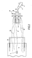
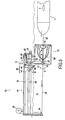
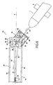
- Figures 5 to 9 do not represent all the parts of the cage 10. In particular, the lower parts of the cage are not represented. In these figures we wanted to show more particularly the receiving means and the guide means.
- Said receiving means 18 comprise an element 32 movable between the inlet and the bottom of the cavity 20.
- the cable 22 passes through this movable element 32, preferably at its center.
- the movable element 32 comprises a cup 34, adapted to receive the nose of the machine 1 (see figure 7 ), which has a central hole 35 through which the cable 22 passes.
- a plurality of guide branches 36 (generally at least two diametrically opposed branches) extend around the periphery of the cup 34 and connect it to the structure 37 of the means The end of each branch 36 can slide relative to this structure 37, so that the movable member 32 can slide between the inlet and the bottom of the cavity 20, as represented by the double arrow A on the figure 5 .
- the cage 10 comprises first locking means 38 (see FIG. figure 5 ) to maintain said receiving means 18 in the vicinity of the inlet of the housing 16, before the machine 1 reaches the cage.
- said receiving means 18 are in position to receive the machine 1 that arrives.
- the cable portion 22 extending between the winch 24 and the receiving means 18 (more precisely between the pulley 40, the passage 23 and the nose of the machine 1 - see Fig. 5 and 6 ) forms a lever arm which is oriented cage 10 facing the nose of the machine 1, which facilitates the recovery of the latter. Note that this orientation of the cage is possible because it can move freely in the water, the (s) cable (s) 9 (70) connecting the cage 10 to the boat 5 being relaxed (s).
- the first blocking means 38 release said receiving means 18 only when the nose of the machine 1 is fully engaged in the receiving means 18 (more precisely in the cavity 20) and is about to penetrate inside the vehicle.
- the first locking means 38 comprise a stop capable of retracting when the machine 1 exerts on it a thrust force greater than a predetermined force.
- the stop is formed by an arm 42 pivotally mounted on the frame 14, at the end of which is mounted a roller 46.
- This arm 42 is connected to a spring 44 whose stiffness is chosen such that from a certain pushing force exerted by the machine 1 on the arm 42, via the receiving means 18, the spring 44 is deformed and allows the arm to retract by pivoting along the arrow B (see figure 5 ).
- Other types of blocking means could, of course, be considered.
- the cage further comprises second blocking means 48 (see FIG. Fig. 6 ) to maintain the movable element 32 of the receiving means 18 at the inlet of the cavity 20, these second blocking means 48 release the movable element 32 when the machine 1 comes into contact with this movable element 32 (more precisely of the cup 34).
- These second locking means 48 are, for example, of the same principle as the first locking means 38 and comprise a stop capable of retracting when the machine 1 exerts on it, via the movable member 32, a thrust force greater than a predetermined force.
- the locking force of the second blocking means 48 is smaller than that of the first blocking means 38, so that when the machine 1 penetrates inside the receiving means 18 (more precisely inside the the cavity 20), the second blocking means 48 yield before the first blocking means 38.
- Said receiving means 18 are integral with a rod 50.
- this rod 50 is oriented vertically (relative to the level of the water, horizontal).
- the rod 50 is mounted on a carriage 52 so as to be pivotable about its axis C, along the double arrow D shown on the Figures 5 to 7 .
- the carriage 52 is guided along the housing 16 of the cage 10, by said guide means.
- the lower end of the rod 50 carries a fork 51 and between the two branches of the fork 51 extends an axis F, perpendicular to the axis C of the rod, around which the receiving means are mounted swivel. Stops 53 limit the vertical pivoting angle of the receiving means 18.
- a guide arm 54 is fixed to the end of the rod 50 so as to be able to drive it and rotate it about its axis C along the double arrow D.
- This arm 54 has a first end engaged with the rod 50 and a second end on which is mounted a roller 56.
- Said guide means comprise first and second superimposed guides 58, 60, extending along the housing 16.
- the first guide 58 guides the carriage 52 along the housing 16. It is formed by a pair of parallel rails 64 and the carriage 52 is equipped with rollers 62 so that it can move along the rails 64, following the double arrow G shown on the figure 6 .
- the second guide 60 guides the guide arm 54 and, thereby, directs the rod 50 and the receiving means 18 by rotating them horizontally along the double arrow D. It is located above the first guide 58. It is formed by a pair of rails 66 which are closer to each other as one moves away from the entrance of the cage 10.
- the guide arm 54 can rotate between these rails 66 according to the double arrow D, between a first position in which the roller 56 is in contact with one of the rails 66, and a second position in which the roller 56 is in contact with the other rail 66. Plus the spacing of the rails 66 is important , plus the freedom of horizontal pivoting arm 54, and therefore the rod 50 and receiving means 18, is large.
- the frame 14 of the cage 10 has on its sides notches 68 open towards the entrance of the cage 10, which allows the passage of the lateral fins 3 of the machine 1 (see Fig. 1 and 4 ).
- the machine 1 being guided and oriented when it enters the cage 10, the fins 3 are housed in the notches 68 and, thus, are not damaged.
- said immobilizing means comprise two rods 26 equipped with pads at their ends, and a mechanism for lifting / lowering these rods.
- the rods 26 slide inside two housings 28 enclosing said mechanism. These housings 28 are fixed on each side of the frame 14, in the vicinity of the entrance of the cage 10. In the lowered position, the rods 26 are in contact with the upper face of the machine 1, as shown in FIGS. figures 4 and 8 . Note that the pressure exerted by the rods 26 on the machine 1 must be controlled in order not to damage the latter.
- the immobilizing means comprise a rod pivotally mounted on the frame 14 and a mechanism, for example a jack, for pivoting this rod.
- the rod carries at its end a hoop which surrounds the upper face of the machine 1.
- the machine 1 has a member projecting from its upper face. After the machine has penetrated inside the housing 16, the hoop lowers and is placed behind the protruding member, which makes it possible to immobilize the machine 1 inside the cage 10 .
- immobilization means are controlled remotely and, preferably, from the boat 5.
- the underside of the machine 1 is supported on a rocker 29, mounted on the frame.
- This rocker 29 comprises at each of its ends a hoop 30, on which the machine 1 rests.
- the hoops 30 extend transversely with respect to the cage 10, under the housing 16. These hoops are easily removed when the machine 1 is placed on a suitable working support present on the boat 5.
- a cable 22 'connected to the nose of the machine 1 is recovered from the boat 5.
- the cable 22' is then connected to a cable 22 "in waiting for the cage 10.
- the cables 22 'and 22 then form the aforementioned cable 22 which is passed through the movable element 32, the passage 23 of the receiving means 18, and around the pulley 40 located at the bottom of the housing 16, and that is connected to the winch 24 of the cage 10 (see figure 5 ).
- the cage 10 is put into the water. It remains connected to the boat 5 via the traction cable 9, also called lifting cable, and other cables 70, said guide. At this point, the cables 9 and 70 are relaxed so that the boat 5 does not drive the cage 10 in its movements. The cage 10 moves freely in the water.
- the winding of the cable 22 is remotely controlled on the winch 24 in order to tow the machine 1 inside the cage 10.
- the cable portion 22 extending between the nose of the machine 1, the receiving means 18 at the entrance to the cage, and the winch 24 (actually the pulley 40) located at the bottom of the 10, forms a lever arm which rotates the cage 10, so that the axis H of the cage is approaching the nose of the machine 1.
- the receiving means 18 are facing the nose of the machine 1 when the latter is approaching, thanks to the cable portion 22 extending between the bottom of the cavity 20 (ie the passage 23), the movable member 32 and the nose of the machine 1.
- the nose of the machine 1 first comes into contact with the movable member 32 and exerts on it, as the traction of the machine 1 continues, a thrust force of greater and greater. Beyond a limit force, the second blocking means 48 release the mobile element 32 which is translated with the nose of the vehicle 1, to the bottom of the cavity 20. The nose of the machine 1 then occupies the cavity 20. The relative movements between the receiving means 18, and thus the machine 1, and the cage 10 are still allowed at this stage. Indeed, the receiving means can pivot vertically and horizontally according to the double arrows E and D. It thus limits the stresses exerted at the nose of the machine 1, related to the relative movements between the machine 1 and the cage 10.
- the machine 1 exerts on the receiving means 18 a thrust force of greater and greater. Beyond a limit force, the first blocking means 38 release the carriage 52 to which the receiving means 18 are connected via the rod 50. The carriage 52 then rolls along the first guide 60, towards the bottom of the housing 16. At the same time, the guide arm 54 is guided along the first guide 58 and its pivoting freedom along the double arrow D gradually decreases. The receiving means 18 and the machine 1 are thus oriented progressively along the main axis H of the cage.
- the cage 10 and the machine 1 are towed from the boat 5, by means of the cable 9, in order to put them back on board the boat 5.
- the cables of guide 70 can be pulled manually, or be connected to a cable winding / unwinding device, for example winches similar to the winch 7.
- the cables 70 and their possible winding / unwinding devices are part of the traction means mounted on the recovery base, within the meaning of the invention.
- the guide cables 70 are used to direct the cage 10 and the machine 1 in order to pass them through the gantry 72.
- the cage 10 is pulled out and the machine 1 out of the water using the cable 9 and the cables 70 are used to guide and pass the cage 10 and the machine 1 through the portico 72, before placing them on the bridge of the boat 5.
- the recovery base is the boat 5 and the machine to be recovered is the machine 1. Originally, the machine 1 is immobilized in the cage 10 and this cage is on board the boat 5.
- the winch 7, the traction cable 9, the gantry 72 and possibly the guide cables 70 are used to launch the cage 10.
- release means comprise a mechanism for raising the rods 26.
- release means are controlled remotely, preferably from the launching base (i.e. the boat 5).
- these traction means comprise the cable winding / unwinding device, that is to say the winch 24 and the cable 22 previously described, and a pulley 74 located at the entrance of the housing 16 of the cage 10.
- the cable 22 is connected to the winch 24, extends to the pulley 74, passes around it, and extends to the carriage 52 to which it is connected.
- the winch 24 is actuated so that the carriage 52, the receiving means 18 and the nose of the machine 1, are pulled through the cable 22 towards the entrance of the housing 16.
- the machine 1 can be made integral with the receiving means 18 and until the end of the output movement. It is then released permanently or, advantageously, by a command from the boat 5, or by a mechanical device placed on the receiving means 18 and automatically triggered at the end of travel of said receiving means.
Landscapes
- Engineering & Computer Science (AREA)
- Mechanical Engineering (AREA)
- Combustion & Propulsion (AREA)
- Ocean & Marine Engineering (AREA)
- Aviation & Aerospace Engineering (AREA)
- Chemical & Material Sciences (AREA)
- Load-Engaging Elements For Cranes (AREA)
- Cleaning In General (AREA)
- Electrical Discharge Machining, Electrochemical Machining, And Combined Machining (AREA)
- Control Of Position, Course, Altitude, Or Attitude Of Moving Bodies (AREA)
- Physical Water Treatments (AREA)
- Drilling And Exploitation, And Mining Machines And Methods (AREA)
- Platform Screen Doors And Railroad Systems (AREA)
Claims (14)
- Vorrichtung zum Bergen eines Unterwasser- oder Wassergerätes (1), umfassend einen Rahmen (14), welcher eine Aufnahme (16) bildet, in welche das Gerät über eine Öffnung eindringen kann, dadurch gekennzeichnet, daß sie umfaßt:- Empfangsmittel (18) zum Aufnehmen eines Teils des Geräts (1), welche in der Lage sind, sich entlang der Aufnahme (16) zu verschieben, wenn das Gerät eindringt, wobei die Empfangsmittel (18) genügend Bewegungsfreiheit bezüglich des Rahmens (14) besitzen, um der Bewegung des Geräts zu folgen, wenn sie sich in der Nähe des Eingangs der Aufnahme befinden, und- Führungsmittel (58, 60), um die Empfangsmittel (18) entlang der Aufnahme (16) zu führen und um die Empfangsmittel und das Gerät auszurichten, wobei ihre Bewegungsfreiheit bezüglich des Rahmens (14) eingegrenzt wird, während das Gerät in die Aufnahme (16) eindringt.
- Vorrichtung nach Anspruch 1, umfassend Zugmittel, welche auf dem Rahmen (14) angeordnet sind und welche es erlauben, das Gerät (1) in die Aufnahme (16) zu ziehen.
- Vorrichtung nach Anspruch 2, bei welcher die Zugmittel eine Vorrichtung (24) zum Aufrollen eines Kabels umfassen, welche es erlaubt, das Gerät (1) in die Aufnahme (16) mittels eines Kabel zu ziehen, das an dem Gerät befestigt ist.
- Vorrichtung nach Anspruch 3, bei welcher die Empfangsmittel (18) einen Hohlraum (20) bilden, welcher geeignet ist, den Teil des Geräts (1) aufzunehmen, und von dem Kabel (22) durchquert werden.
- Vorrichtung nach einem der Ansprüche 1 bis 4, umfassend erste Blockiermittel (38), um die Empfangsmittel (18) in der Nähe der Öffnung der Aufnahme (16) zu halten, wobei die ersten Blockiermittel die Empfangsmittel entriegeln, wenn der Teil des Geräts (1) in den Empfangsmitteln andockt.
- Vorrichtung nach Anspruch 4 und einem der Ansprüche 1 bis 5, bei welcher die Empfangsmittel (18) zwischen dem Eingang und dem Boden des Hohlraums (20), ein bewegliches Element (32) umfassen, durch welches das Kabel (22) verläuft.
- Vorrichtung nach Anspruch 6, umfassend zweite Blockiermittel (48), um das bewegliche Element (32) am Eingang des Hohlraums (20) zu halten, wobei die zweiten Blockiermittel das bewegliche Element entriegeln, wenn das Gerät (1) das bewegliche Element berührt.
- Vorrichtung nach einem der Ansprüche 1 bis 7, in welcher die Empfangsmittel (18) mit einer Stange (50) fest verbunden sind, wobei die Stange auf einem Wagen (52) so angeordnet ist, daß sie um ihre eigene Achse (C) schwenken kann, und wobei der Wagen entlang der Aufnahme durch die Führungsmittel (58, 60) geführt wird.
- Vorrichtung nach Anspruch 8, bei welcher die Empfangsmittel (18) um eine zur Achse (C) senkrechte Achse (F) auf der Stange (50) schwenkbar angeordnet sind.
- Vorrichtung nach Anspruch 8 oder 9, bei welcher ein Führungsarm (54) am Ende der Stange (50) fixiert ist und bei welcher die Führungsmittel erste und zweite überlagerte Führungen (58, 60) umfassen, welche sich entlang der Aufnahme (16) erstrecken, wobei die erste Führung (58) den Wagen (52) entlang der Aufnahme führt und wobei die zweite Führung (60) den Führungsarm führt und dadurch die Stange und die Empfangsmittel (18) ausrichtet.
- Vorrichtung nach Anspruch 10, bei welcher die zweite Führung (60) von einem Paar Schienen (66) gebildet wird, wobei die Schienen untereinander näher rücken, wenn man sich von der Öffnung der Aufnahme (16) entfernt, so daß der Ausschlag des Führungsarmes (54) eingegrenzt wird und dadurch die Stange (50) und die Empfangsmittel (18) ausgerichtet werden.
- Vorrichtung nach einem der Ansprüche 1 bis 11, welche geeignet ist, auf dem Wasser zu treiben.
- Verwendung einer Vorrichtung nach einem der Ansprüche 1 bis 12 zum Bergen und/oder Zuwasserlassen eines Unterwasser- oder Wassergeräts (1).
- Einrichtung zum Bergen eines Unterwasser- oder Wassergeräts (1) basierend auf einer Bergungsplattform (5), umfassend eine Vorrichtung zum Bergen nach einem der Ansprüche 1 bis 12 und Zugmittel (7), welche auf der Bergungsplattform montiert werden und welche das Ziehen der Vorrichtung über mindestens ein flexibles Bindeglied (9, 70) erlauben.
Applications Claiming Priority (2)
| Application Number | Priority Date | Filing Date | Title |
|---|---|---|---|
| FR0653127A FR2904287B1 (fr) | 2006-07-26 | 2006-07-26 | Appareil de recuperation d'un engin sous-marin ou marin |
| PCT/FR2007/051721 WO2008012472A1 (fr) | 2006-07-26 | 2007-07-25 | Appareil de recuperation d'un engin sous-marin ou marin |
Publications (2)
| Publication Number | Publication Date |
|---|---|
| EP2043913A1 EP2043913A1 (de) | 2009-04-08 |
| EP2043913B1 true EP2043913B1 (de) | 2009-12-02 |
Family
ID=37898275
Family Applications (1)
| Application Number | Title | Priority Date | Filing Date |
|---|---|---|---|
| EP07823638A Active EP2043913B1 (de) | 2006-07-26 | 2007-07-25 | Vorrichtung zur wiederherstellung eines unterwasser- oder wasserfahrzeugs |
Country Status (9)
| Country | Link |
|---|---|
| US (1) | US20090308299A1 (de) |
| EP (1) | EP2043913B1 (de) |
| JP (1) | JP2009544520A (de) |
| AT (1) | ATE450442T1 (de) |
| CA (1) | CA2658975C (de) |
| DE (1) | DE602007003607D1 (de) |
| DK (1) | DK2043913T3 (de) |
| FR (1) | FR2904287B1 (de) |
| WO (1) | WO2008012472A1 (de) |
Cited By (1)
| Publication number | Priority date | Publication date | Assignee | Title |
|---|---|---|---|---|
| CN111409796A (zh) * | 2019-01-07 | 2020-07-14 | 中国科学院沈阳自动化研究所 | 一种用于自主回收水下机器人的绳缆捕获式机构 |
Families Citing this family (36)
| Publication number | Priority date | Publication date | Assignee | Title |
|---|---|---|---|---|
| EP2821339B1 (de) | 2006-01-20 | 2023-11-08 | Liquid Robotics, Inc. | Wellenenergie |
| US20140263851A1 (en) * | 2013-03-14 | 2014-09-18 | Liquid Robotics, Inc. | Water Vehicles |
| CN101622173B (zh) | 2007-03-02 | 2013-03-27 | 里奎德机器人技术公司 | 水上载体 |
| FR2931792B1 (fr) | 2008-06-03 | 2010-11-12 | Thales Sa | Systeme pour la mise a l'eau et la recuperation automatiques d'un drone sous-marin |
| US8215889B2 (en) * | 2008-10-24 | 2012-07-10 | Oceaneering International, Inc. | System and method for high current recovery cursor |
| CN101804855A (zh) * | 2010-03-30 | 2010-08-18 | 中国船舶重工集团公司第七〇二研究所 | 遥控潜水器的水下引导捕获装置 |
| FR2963924B1 (fr) | 2010-08-18 | 2012-09-14 | Ifremer | Dispositif pour la recuperation d'un engin marin ou sous-marin |
| FR2969574B1 (fr) * | 2010-12-23 | 2013-11-01 | Eca | Dispositif de mise a l'eau et de recuperation d'un engin marin, et procede de mise a l'eau et de recuperation associe. |
| FR2969573B1 (fr) * | 2010-12-23 | 2013-02-08 | Eca | Dispositif de mise a l'eau et de recuperation d'un engin submersible ou de surface. |
| EP3267275B1 (de) | 2011-03-17 | 2019-10-16 | Liquid Robotics, Inc. | Wellengetriebene vorrichtungen zum ineinanderstapeln |
| EP3208185B1 (de) | 2011-06-28 | 2019-05-01 | Liquid Robotics, Inc. | Wasserfahrzeug zur gewinnung von antriebskraft wie auch elektrischer energie aus wellenbewegung |
| GB2496608B (en) * | 2011-11-15 | 2014-06-18 | Subsea 7 Ltd | Launch and recovery techniques for submersible vehicles and other payloads |
| FR2989352B1 (fr) | 2012-04-12 | 2014-05-09 | Dcns | Dispositif d'amarrage pour un vehicule sous-marin, systeme d'amarrage et base de recuperation |
| US9359046B2 (en) * | 2013-10-02 | 2016-06-07 | Raytheon Company | Submersible towed body deployment and recovery device |
| JP6443820B2 (ja) * | 2014-06-10 | 2018-12-26 | 株式会社Ihi | 水中航走体の収容装置及び収容方法 |
| CN104029792A (zh) * | 2014-06-13 | 2014-09-10 | 天津汉海环保设备有限公司 | 一种航行器捕获器 |
| NL2015802B1 (en) * | 2015-11-17 | 2017-06-02 | Fugro N V | Method of and system for hauling a marine equipment unit, a marine equipment unit and a carrier. |
| CN105501415A (zh) * | 2015-12-15 | 2016-04-20 | 浙江大学 | 一种用于深海auv入坞的末端自动对接装置及方法 |
| CN106564573B (zh) * | 2016-10-28 | 2018-01-12 | 浙江大学 | 基于光伏发电的剖面观测与水下接驳系统 |
| DE102016222225A1 (de) * | 2016-11-11 | 2018-05-17 | Fraunhofer-Gesellschaft zur Förderung der angewandten Forschung e.V. | Bergevorrichtung und zugehöriges verfahren |
| US9828822B1 (en) * | 2017-02-27 | 2017-11-28 | Chevron U.S.A. Inc. | BOP and production tree landing assist systems and methods |
| WO2019113137A2 (en) * | 2017-12-04 | 2019-06-13 | Gordon John Taylor Ii | Data retrieval and transmitting marine exploration vessel systems |
| CN109911151B (zh) * | 2017-12-13 | 2020-12-15 | 中国科学院沈阳自动化研究所 | 一种水下移动载体推行装置 |
| KR101998506B1 (ko) * | 2018-01-11 | 2019-07-09 | 국방과학연구소 | 수중 탐색 장치를 위한 전개 회수 장치 및 그 제어 방법 |
| WO2019236797A1 (en) * | 2018-06-06 | 2019-12-12 | Oceaneering International, Inc. | Rov deployed power buoy system |
| CN109080795B (zh) * | 2018-08-01 | 2020-05-29 | 国家海洋局第一海洋研究所 | 一种滑翔湍流剖面仪布放装置及其操作方法 |
| NO345094B1 (en) | 2018-09-21 | 2020-09-28 | Usea As | A marine structure comprising a launch and recovery system |
| CN111361693B (zh) * | 2018-12-25 | 2021-07-27 | 中国科学院沈阳自动化研究所 | 一种应用于布放回收水下拖曳体的自动锁紧和解锁机构 |
| CN111361687B (zh) * | 2018-12-25 | 2021-07-27 | 中国科学院沈阳自动化研究所 | 应用于布放回收水下拖曳体的自动锁紧和解锁机构及方法 |
| FR3108091B1 (fr) * | 2020-03-16 | 2024-04-26 | Ixblue | Système de manutention de drones marins ou sous-marins par ponton flottant à module d’interface de drone amovible, navire adapté |
| CN111731456B (zh) * | 2020-06-22 | 2022-07-05 | 西北工业大学 | 一种基于水下航行器的中小型回转体auv释放回收装置 |
| KR102387761B1 (ko) * | 2020-07-31 | 2022-04-15 | 한국로봇융합연구원 | 수중 글라이더 인양용 인양 플랫폼 및 이를 이용한 인양 방법 |
| US12128991B2 (en) * | 2020-10-23 | 2024-10-29 | Calzoni S.R.L. | Guided lifting system |
| US11485461B2 (en) | 2021-03-15 | 2022-11-01 | Tridentis Advanced Marine Vehicles, LLC | Device and method for launching and recovering an unmanned underwater vehicle |
| CN113772022B (zh) * | 2021-08-13 | 2022-07-01 | 鹏城实验室 | 水下机器人回收装置与母船 |
| CN114802619A (zh) * | 2021-10-12 | 2022-07-29 | 深圳海兰云数据中心科技有限公司 | 一种用于水下数据舱的维护平台 |
Family Cites Families (11)
| Publication number | Priority date | Publication date | Assignee | Title |
|---|---|---|---|---|
| NL36793C (de) * | 1932-05-11 | |||
| US3034471A (en) * | 1959-08-25 | 1962-05-15 | Vare Ind | Method of nesting an underwater towed vehicle |
| US3626703A (en) * | 1969-11-18 | 1971-12-14 | Twanoh Marine Charters Inc | Underwater exploration and recovery vehicle |
| US3943875A (en) * | 1973-03-05 | 1976-03-16 | British Columbia Research Council | Method and apparatus for launching and recovering submersibles |
| US4306413A (en) * | 1975-06-30 | 1981-12-22 | The United States Of America As Represented By The Secretary Of The Navy | Hydraulic power and control system |
| US4304189A (en) * | 1979-10-25 | 1981-12-08 | The United States Of America As Represented By The Secretary Of The Navy | Telescopic launch and retrieval chute |
| US5447115A (en) * | 1994-06-30 | 1995-09-05 | The United States Of America As Represented By The Secretary Of The Navy | Underwater vehicle recovery system |
| IT1311837B1 (it) | 1999-05-19 | 2002-03-19 | Studio 3 Ingegneria Srl | Dispositivo di attracco per veicoli autonomi sottomarini semoventi |
| FR2823485B1 (fr) * | 2001-04-13 | 2003-08-01 | Eca | Dispositif de mise a l'eau et de recuperation d'un vehicule sous-marin et procede de mise en oeuvre |
| DE102007031156B4 (de) * | 2007-06-11 | 2009-04-16 | Diehl Bgt Defence Gmbh & Co. Kg | Vorrichtung und Verfahren zur Aussetzung und Bergung eines Unterwasserfahrzeugs und Verfahren zur Andockung eines Unterwasserfahrzeugs an eine solche Vorrichtung |
| US7854569B1 (en) * | 2008-12-11 | 2010-12-21 | The United States Of America As Represented By The Secretary Of The Navy | Underwater unmanned vehicle recovery system and method |
-
2006
- 2006-07-26 FR FR0653127A patent/FR2904287B1/fr not_active Expired - Fee Related
-
2007
- 2007-07-25 CA CA2658975A patent/CA2658975C/en active Active
- 2007-07-25 US US12/375,067 patent/US20090308299A1/en not_active Abandoned
- 2007-07-25 EP EP07823638A patent/EP2043913B1/de active Active
- 2007-07-25 DE DE602007003607T patent/DE602007003607D1/de active Active
- 2007-07-25 WO PCT/FR2007/051721 patent/WO2008012472A1/fr not_active Ceased
- 2007-07-25 DK DK07823638.7T patent/DK2043913T3/da active
- 2007-07-25 JP JP2009521319A patent/JP2009544520A/ja active Pending
- 2007-07-25 AT AT07823638T patent/ATE450442T1/de not_active IP Right Cessation
Cited By (2)
| Publication number | Priority date | Publication date | Assignee | Title |
|---|---|---|---|---|
| CN111409796A (zh) * | 2019-01-07 | 2020-07-14 | 中国科学院沈阳自动化研究所 | 一种用于自主回收水下机器人的绳缆捕获式机构 |
| CN111409796B (zh) * | 2019-01-07 | 2021-07-20 | 中国科学院沈阳自动化研究所 | 一种用于自主回收水下机器人的绳缆捕获式机构 |
Also Published As
| Publication number | Publication date |
|---|---|
| DK2043913T3 (da) | 2010-04-19 |
| FR2904287A1 (fr) | 2008-02-01 |
| CA2658975A1 (en) | 2008-01-31 |
| ATE450442T1 (de) | 2009-12-15 |
| EP2043913A1 (de) | 2009-04-08 |
| FR2904287B1 (fr) | 2008-10-24 |
| JP2009544520A (ja) | 2009-12-17 |
| US20090308299A1 (en) | 2009-12-17 |
| CA2658975C (en) | 2015-05-19 |
| WO2008012472A1 (fr) | 2008-01-31 |
| DE602007003607D1 (de) | 2010-01-14 |
Similar Documents
| Publication | Publication Date | Title |
|---|---|---|
| EP2043913B1 (de) | Vorrichtung zur wiederherstellung eines unterwasser- oder wasserfahrzeugs | |
| EP2043911B1 (de) | Anlage und verfahren zur wiederherstellung eines unterwasser- oder wasserfahrzeugs | |
| EP3902742B1 (de) | Andockvorrichtung für ein unterwasserfahrzeug | |
| EP2468620B1 (de) | Vorrichtung zur Zuwasserlassung und Bergung eines Wassergeräts, und entsprechendes Verfahren zur Zuwasserlassung und Bergung | |
| EP3906188B1 (de) | Andockvorrichtung für ein unterwasserfahrzeug | |
| EP2155543B1 (de) | U-boot mit vorrichtung zur freisetzung und einholung eines sekundären unterwasserfahrzeuges | |
| EP2648970B1 (de) | System zum freigeben und bergen eines unterwassergeräts | |
| EP2855252B1 (de) | System zum starten und zurückholen von unterwasserfahrzeugen, insbesondere gezogenen unterwasserfahrzeugen | |
| CA2380816A1 (fr) | Dispositif de mise a l'eau et de recuperation d'un vehicule sous-marin et procede de mise en oeuvre | |
| EP3209546B1 (de) | System zum aussetzen und bergen von see- und unterseevorrichtungen mit unterstützung durch kippbare schutzkomponenten | |
| FR3062844A1 (fr) | Systeme de mise a l'eau et de recuperation d'un engin propulse depuis le pont d'un navire porteur | |
| EP2468621A1 (de) | Vorrichtung zur Zuwasserlassung und Bergung eines Unterwasser- oder Oberflächengeräts | |
| EP3976461B1 (de) | Unterwasservorrichtung und unterwassersystem | |
| EP3976460B1 (de) | Sonarvorrichtung und sonarsystem | |
| EP4493456B1 (de) | Geschlepptes unterwasserfahrzeug und system zur bergung solch eines unterwasserfahrzeugs | |
| EP4452742A1 (de) | System zum manövrieren eines wasserfahrzeugs |
Legal Events
| Date | Code | Title | Description |
|---|---|---|---|
| PUAI | Public reference made under article 153(3) epc to a published international application that has entered the european phase |
Free format text: ORIGINAL CODE: 0009012 |
|
| 17P | Request for examination filed |
Effective date: 20090123 |
|
| AK | Designated contracting states |
Kind code of ref document: A1 Designated state(s): AT BE BG CH CY CZ DE DK EE ES FI FR GB GR HU IE IS IT LI LT LU LV MC MT NL PL PT RO SE SI SK TR |
|
| AX | Request for extension of the european patent |
Extension state: AL BA HR MK RS |
|
| GRAP | Despatch of communication of intention to grant a patent |
Free format text: ORIGINAL CODE: EPIDOSNIGR1 |
|
| GRAS | Grant fee paid |
Free format text: ORIGINAL CODE: EPIDOSNIGR3 |
|
| GRAA | (expected) grant |
Free format text: ORIGINAL CODE: 0009210 |
|
| AK | Designated contracting states |
Kind code of ref document: B1 Designated state(s): AT BE BG CH CY CZ DE DK EE ES FI FR GB GR HU IE IS IT LI LT LU LV MC MT NL PL PT RO SE SI SK TR |
|
| REG | Reference to a national code |
Ref country code: GB Ref legal event code: FG4D Free format text: NOT ENGLISH |
|
| REG | Reference to a national code |
Ref country code: CH Ref legal event code: EP |
|
| REG | Reference to a national code |
Ref country code: IE Ref legal event code: FG4D |
|
| REF | Corresponds to: |
Ref document number: 602007003607 Country of ref document: DE Date of ref document: 20100114 Kind code of ref document: P |
|
| REG | Reference to a national code |
Ref country code: SE Ref legal event code: TRGR |
|
| REG | Reference to a national code |
Ref country code: NL Ref legal event code: VDEP Effective date: 20091202 |
|
| REG | Reference to a national code |
Ref country code: DK Ref legal event code: T3 |
|
| PG25 | Lapsed in a contracting state [announced via postgrant information from national office to epo] |
Ref country code: FI Free format text: LAPSE BECAUSE OF FAILURE TO SUBMIT A TRANSLATION OF THE DESCRIPTION OR TO PAY THE FEE WITHIN THE PRESCRIBED TIME-LIMIT Effective date: 20091202 Ref country code: LT Free format text: LAPSE BECAUSE OF FAILURE TO SUBMIT A TRANSLATION OF THE DESCRIPTION OR TO PAY THE FEE WITHIN THE PRESCRIBED TIME-LIMIT Effective date: 20091202 |
|
| LTIE | Lt: invalidation of european patent or patent extension |
Effective date: 20091202 |
|
| PG25 | Lapsed in a contracting state [announced via postgrant information from national office to epo] |
Ref country code: SI Free format text: LAPSE BECAUSE OF FAILURE TO SUBMIT A TRANSLATION OF THE DESCRIPTION OR TO PAY THE FEE WITHIN THE PRESCRIBED TIME-LIMIT Effective date: 20091202 Ref country code: PL Free format text: LAPSE BECAUSE OF FAILURE TO SUBMIT A TRANSLATION OF THE DESCRIPTION OR TO PAY THE FEE WITHIN THE PRESCRIBED TIME-LIMIT Effective date: 20091202 Ref country code: LV Free format text: LAPSE BECAUSE OF FAILURE TO SUBMIT A TRANSLATION OF THE DESCRIPTION OR TO PAY THE FEE WITHIN THE PRESCRIBED TIME-LIMIT Effective date: 20091202 Ref country code: CY Free format text: LAPSE BECAUSE OF FAILURE TO SUBMIT A TRANSLATION OF THE DESCRIPTION OR TO PAY THE FEE WITHIN THE PRESCRIBED TIME-LIMIT Effective date: 20091202 |
|
| PG25 | Lapsed in a contracting state [announced via postgrant information from national office to epo] |
Ref country code: AT Free format text: LAPSE BECAUSE OF FAILURE TO SUBMIT A TRANSLATION OF THE DESCRIPTION OR TO PAY THE FEE WITHIN THE PRESCRIBED TIME-LIMIT Effective date: 20091202 |
|
| REG | Reference to a national code |
Ref country code: IE Ref legal event code: FD4D |
|
| PG25 | Lapsed in a contracting state [announced via postgrant information from national office to epo] |
Ref country code: ES Free format text: LAPSE BECAUSE OF FAILURE TO SUBMIT A TRANSLATION OF THE DESCRIPTION OR TO PAY THE FEE WITHIN THE PRESCRIBED TIME-LIMIT Effective date: 20100313 Ref country code: EE Free format text: LAPSE BECAUSE OF FAILURE TO SUBMIT A TRANSLATION OF THE DESCRIPTION OR TO PAY THE FEE WITHIN THE PRESCRIBED TIME-LIMIT Effective date: 20091202 Ref country code: BG Free format text: LAPSE BECAUSE OF FAILURE TO SUBMIT A TRANSLATION OF THE DESCRIPTION OR TO PAY THE FEE WITHIN THE PRESCRIBED TIME-LIMIT Effective date: 20100302 Ref country code: IE Free format text: LAPSE BECAUSE OF FAILURE TO SUBMIT A TRANSLATION OF THE DESCRIPTION OR TO PAY THE FEE WITHIN THE PRESCRIBED TIME-LIMIT Effective date: 20091202 Ref country code: RO Free format text: LAPSE BECAUSE OF FAILURE TO SUBMIT A TRANSLATION OF THE DESCRIPTION OR TO PAY THE FEE WITHIN THE PRESCRIBED TIME-LIMIT Effective date: 20091202 Ref country code: PT Free format text: LAPSE BECAUSE OF FAILURE TO SUBMIT A TRANSLATION OF THE DESCRIPTION OR TO PAY THE FEE WITHIN THE PRESCRIBED TIME-LIMIT Effective date: 20100402 Ref country code: NL Free format text: LAPSE BECAUSE OF FAILURE TO SUBMIT A TRANSLATION OF THE DESCRIPTION OR TO PAY THE FEE WITHIN THE PRESCRIBED TIME-LIMIT Effective date: 20091202 |
|
| PG25 | Lapsed in a contracting state [announced via postgrant information from national office to epo] |
Ref country code: SK Free format text: LAPSE BECAUSE OF FAILURE TO SUBMIT A TRANSLATION OF THE DESCRIPTION OR TO PAY THE FEE WITHIN THE PRESCRIBED TIME-LIMIT Effective date: 20091202 Ref country code: CZ Free format text: LAPSE BECAUSE OF FAILURE TO SUBMIT A TRANSLATION OF THE DESCRIPTION OR TO PAY THE FEE WITHIN THE PRESCRIBED TIME-LIMIT Effective date: 20091202 |
|
| PLBE | No opposition filed within time limit |
Free format text: ORIGINAL CODE: 0009261 |
|
| STAA | Information on the status of an ep patent application or granted ep patent |
Free format text: STATUS: NO OPPOSITION FILED WITHIN TIME LIMIT |
|
| PG25 | Lapsed in a contracting state [announced via postgrant information from national office to epo] |
Ref country code: GR Free format text: LAPSE BECAUSE OF FAILURE TO SUBMIT A TRANSLATION OF THE DESCRIPTION OR TO PAY THE FEE WITHIN THE PRESCRIBED TIME-LIMIT Effective date: 20100303 |
|
| 26N | No opposition filed |
Effective date: 20100903 |
|
| BERE | Be: lapsed |
Owner name: INSTITUT FRANCAIS DE RECHERCHE POUR L'EXPLOITATIO Effective date: 20100731 |
|
| PG25 | Lapsed in a contracting state [announced via postgrant information from national office to epo] |
Ref country code: MC Free format text: LAPSE BECAUSE OF NON-PAYMENT OF DUE FEES Effective date: 20100731 |
|
| PG25 | Lapsed in a contracting state [announced via postgrant information from national office to epo] |
Ref country code: IT Free format text: LAPSE BECAUSE OF FAILURE TO SUBMIT A TRANSLATION OF THE DESCRIPTION OR TO PAY THE FEE WITHIN THE PRESCRIBED TIME-LIMIT Effective date: 20091202 |
|
| PG25 | Lapsed in a contracting state [announced via postgrant information from national office to epo] |
Ref country code: BE Free format text: LAPSE BECAUSE OF NON-PAYMENT OF DUE FEES Effective date: 20100731 |
|
| PGFP | Annual fee paid to national office [announced via postgrant information from national office to epo] |
Ref country code: DK Payment date: 20110621 Year of fee payment: 5 |
|
| PGFP | Annual fee paid to national office [announced via postgrant information from national office to epo] |
Ref country code: DE Payment date: 20110713 Year of fee payment: 5 |
|
| PG25 | Lapsed in a contracting state [announced via postgrant information from national office to epo] |
Ref country code: MT Free format text: LAPSE BECAUSE OF FAILURE TO SUBMIT A TRANSLATION OF THE DESCRIPTION OR TO PAY THE FEE WITHIN THE PRESCRIBED TIME-LIMIT Effective date: 20091202 |
|
| REG | Reference to a national code |
Ref country code: CH Ref legal event code: PL |
|
| PG25 | Lapsed in a contracting state [announced via postgrant information from national office to epo] |
Ref country code: CH Free format text: LAPSE BECAUSE OF NON-PAYMENT OF DUE FEES Effective date: 20110731 Ref country code: LI Free format text: LAPSE BECAUSE OF NON-PAYMENT OF DUE FEES Effective date: 20110731 |
|
| PG25 | Lapsed in a contracting state [announced via postgrant information from national office to epo] |
Ref country code: HU Free format text: LAPSE BECAUSE OF FAILURE TO SUBMIT A TRANSLATION OF THE DESCRIPTION OR TO PAY THE FEE WITHIN THE PRESCRIBED TIME-LIMIT Effective date: 20100603 Ref country code: LU Free format text: LAPSE BECAUSE OF NON-PAYMENT OF DUE FEES Effective date: 20100725 |
|
| PG25 | Lapsed in a contracting state [announced via postgrant information from national office to epo] |
Ref country code: TR Free format text: LAPSE BECAUSE OF FAILURE TO SUBMIT A TRANSLATION OF THE DESCRIPTION OR TO PAY THE FEE WITHIN THE PRESCRIBED TIME-LIMIT Effective date: 20091202 |
|
| REG | Reference to a national code |
Ref country code: DK Ref legal event code: EBP |
|
| PG25 | Lapsed in a contracting state [announced via postgrant information from national office to epo] |
Ref country code: DE Free format text: LAPSE BECAUSE OF NON-PAYMENT OF DUE FEES Effective date: 20130201 Ref country code: IS Free format text: LAPSE BECAUSE OF FAILURE TO SUBMIT A TRANSLATION OF THE DESCRIPTION OR TO PAY THE FEE WITHIN THE PRESCRIBED TIME-LIMIT Effective date: 20130201 |
|
| REG | Reference to a national code |
Ref country code: DE Ref legal event code: R119 Ref document number: 602007003607 Country of ref document: DE Effective date: 20130201 |
|
| PG25 | Lapsed in a contracting state [announced via postgrant information from national office to epo] |
Ref country code: DK Free format text: LAPSE BECAUSE OF NON-PAYMENT OF DUE FEES Effective date: 20120731 |
|
| REG | Reference to a national code |
Ref country code: FR Ref legal event code: PLFP Year of fee payment: 10 |
|
| PGFP | Annual fee paid to national office [announced via postgrant information from national office to epo] |
Ref country code: IS Payment date: 20110731 Year of fee payment: 5 |
|
| REG | Reference to a national code |
Ref country code: FR Ref legal event code: PLFP Year of fee payment: 11 |
|
| REG | Reference to a national code |
Ref country code: FR Ref legal event code: PLFP Year of fee payment: 12 |
|
| PGFP | Annual fee paid to national office [announced via postgrant information from national office to epo] |
Ref country code: GB Payment date: 20230725 Year of fee payment: 17 |
|
| PGFP | Annual fee paid to national office [announced via postgrant information from national office to epo] |
Ref country code: SE Payment date: 20230721 Year of fee payment: 17 |
|
| REG | Reference to a national code |
Ref country code: SE Ref legal event code: EUG |
|
| GBPC | Gb: european patent ceased through non-payment of renewal fee |
Effective date: 20240725 |
|
| PG25 | Lapsed in a contracting state [announced via postgrant information from national office to epo] |
Ref country code: GB Free format text: LAPSE BECAUSE OF NON-PAYMENT OF DUE FEES Effective date: 20240725 |
|
| PG25 | Lapsed in a contracting state [announced via postgrant information from national office to epo] |
Ref country code: SE Free format text: LAPSE BECAUSE OF NON-PAYMENT OF DUE FEES Effective date: 20240726 |
|
| PGFP | Annual fee paid to national office [announced via postgrant information from national office to epo] |
Ref country code: FR Payment date: 20250724 Year of fee payment: 19 |