EP2044878A2 - Vorrichtung zur Darstellung von Optotypen - Google Patents
Vorrichtung zur Darstellung von Optotypen Download PDFInfo
- Publication number
- EP2044878A2 EP2044878A2 EP08165166A EP08165166A EP2044878A2 EP 2044878 A2 EP2044878 A2 EP 2044878A2 EP 08165166 A EP08165166 A EP 08165166A EP 08165166 A EP08165166 A EP 08165166A EP 2044878 A2 EP2044878 A2 EP 2044878A2
- Authority
- EP
- European Patent Office
- Prior art keywords
- green
- red
- test chart
- optotype
- filter
- Prior art date
- Legal status (The legal status is an assumption and is not a legal conclusion. Google has not performed a legal analysis and makes no representation as to the accuracy of the status listed.)
- Granted
Links
- 238000012360 testing method Methods 0.000 claims abstract description 139
- 230000000007 visual effect Effects 0.000 claims abstract description 39
- 238000011056 performance test Methods 0.000 claims abstract description 37
- 230000005540 biological transmission Effects 0.000 claims abstract description 16
- 230000004304 visual acuity Effects 0.000 claims abstract description 9
- 235000019646 color tone Nutrition 0.000 abstract description 7
- 208000004350 Strabismus Diseases 0.000 description 11
- 238000012790 confirmation Methods 0.000 description 10
- 238000005259 measurement Methods 0.000 description 9
- 230000006870 function Effects 0.000 description 6
- 230000004927 fusion Effects 0.000 description 6
- 239000003086 colorant Substances 0.000 description 5
- 230000004438 eyesight Effects 0.000 description 3
- 201000011573 Aniseikonia Diseases 0.000 description 2
- 206010020015 Heterophoria Diseases 0.000 description 2
- 238000010586 diagram Methods 0.000 description 2
- 239000004973 liquid crystal related substance Substances 0.000 description 2
- 238000012986 modification Methods 0.000 description 2
- 230000004048 modification Effects 0.000 description 2
- 208000028780 ocular motility disease Diseases 0.000 description 2
- 230000001629 suppression Effects 0.000 description 2
- 208000003164 Diplopia Diseases 0.000 description 1
- 238000012937 correction Methods 0.000 description 1
- 230000003247 decreasing effect Effects 0.000 description 1
- 230000036040 emmetropia Effects 0.000 description 1
- 229910052736 halogen Inorganic materials 0.000 description 1
- 150000002367 halogens Chemical class 0.000 description 1
- 230000001771 impaired effect Effects 0.000 description 1
- 238000000034 method Methods 0.000 description 1
- 230000003287 optical effect Effects 0.000 description 1
- 238000002834 transmittance Methods 0.000 description 1
Images



Classifications
-
- A—HUMAN NECESSITIES
- A61—MEDICAL OR VETERINARY SCIENCE; HYGIENE
- A61B—DIAGNOSIS; SURGERY; IDENTIFICATION
- A61B3/00—Apparatus for testing the eyes; Instruments for examining the eyes
- A61B3/02—Subjective types, i.e. testing apparatus requiring the active assistance of the patient
- A61B3/028—Subjective types, i.e. testing apparatus requiring the active assistance of the patient for testing visual acuity; for determination of refraction, e.g. phoropters
- A61B3/032—Devices for presenting test symbols or characters, e.g. test chart projectors
-
- A—HUMAN NECESSITIES
- A61—MEDICAL OR VETERINARY SCIENCE; HYGIENE
- A61B—DIAGNOSIS; SURGERY; IDENTIFICATION
- A61B3/00—Apparatus for testing the eyes; Instruments for examining the eyes
- A61B3/0016—Operational features thereof
- A61B3/0033—Operational features thereof characterised by user input arrangements
-
- A—HUMAN NECESSITIES
- A61—MEDICAL OR VETERINARY SCIENCE; HYGIENE
- A61B—DIAGNOSIS; SURGERY; IDENTIFICATION
- A61B3/00—Apparatus for testing the eyes; Instruments for examining the eyes
- A61B3/02—Subjective types, i.e. testing apparatus requiring the active assistance of the patient
- A61B3/028—Subjective types, i.e. testing apparatus requiring the active assistance of the patient for testing visual acuity; for determination of refraction, e.g. phoropters
- A61B3/032—Devices for presenting test symbols or characters, e.g. test chart projectors
- A61B3/0325—Devices for presenting test symbols or characters, e.g. test chart projectors provided with red and green targets
-
- A—HUMAN NECESSITIES
- A61—MEDICAL OR VETERINARY SCIENCE; HYGIENE
- A61B—DIAGNOSIS; SURGERY; IDENTIFICATION
- A61B3/00—Apparatus for testing the eyes; Instruments for examining the eyes
- A61B3/02—Subjective types, i.e. testing apparatus requiring the active assistance of the patient
- A61B3/08—Subjective types, i.e. testing apparatus requiring the active assistance of the patient for testing binocular or stereoscopic vision, e.g. strabismus
Definitions
- the present invention relates to an optotype presenting apparatus which presents an optotype and/or a test chart for testing visual acuity and binocular visual performance of eyes of an examinee.
- an optotype presenting apparatus such that an optotype and/or a test chart drawn on a disk is illuminated from behind with a light source such as a halogen lamp and the optotype and/or the test chart is projected onto a screen at a far distance for a test of such as 5 meters, and an optotype presenting apparatus having a display such as a color liquid crystal display (see Japanese Patent Application Unexamined Publication No. Hei05-130975 corresponding to U.S. Patent No. 5,638,082 , and Japanese Patent Application Unexamined Publication No. 2006-42978 ).
- test chart presented by the optotype presenting apparatus examples include a visual acuity test chart used in a refractive power test (see Fig. 1 ), a red-green test chart for testing overcorrection, a phoria test chart, a fusion test chart, and a stereoscopic vision test chart, which are test charts for testing binocular visual performance by making right and left eyes respectively observe different optotypes.
- the binocular visual performance test chart includes a red-green binocular visual performance test chart such that different optotypes are presented to right and left eyes of an examinee with a red filter placed in front of one of the eyes and a green filter placed in front of the other eye.
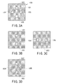
- Figs. 3A to 3D show an example of a Worth four-point chart used for testing fusion and suppression of eyes.
- a Worth four-point chart (test chart) 100 includes, on a black background 101, a circular red optotype 102 on the upper side, circular green optotypes 104 and 105 respectively on the left side and the right side, and a circular white optotype 103 on the lower side.
- test chart 100 is observed through a red filter placed in front of a right eye, the red optotype 102 and the white optotype 103 are visually perceived in red as shown in Fig. 3B .
- the green optotypes 104 and 105 are visually perceived in black and appear merged with the black background 101 because green light therefrom is cut off by the red filter.
- the red optotype 102 is visually perceived in black and appears merged with the black background 101 as shown in Fig. 3C because red light therefrom is cut off by the green filter.
- the green optotypes 104 and 105 and the white optotype 103 are visually perceived in green.
- the right eye is suppressed if the optotypes are visually perceived in the state shown in Fig. 3C .
- the red optotype 102 and the green optotypes 104 and 105 are simultaneously visually perceived, and the white optotype 103 is visually perceived alternately in red and green.
- a subjective refractive power measurement apparatus capable of switching between a red filter and a green filter to be respectively placed in right and left test windows, or red and green spectacles with a red filter and a green filter are used.
- red filters to be used in the subjective refractive power measurement apparatus and the red and green spectacles have different wavelength transmission characteristics even if they are similarly red.
- Green filters also have different wavelength transmission characteristics in some cases. These differences result from different apparatus manufacturers, or even when the red filters and/or the green filters are produced by one apparatus manufacturer, there are variations between the red filters and/or between the green filters. Therefore, there is a problem that when a subjective refractive power measurement apparatus or red and green spectacles are used, a green optotype and a red optotype are not visually perceived independently by right and left eyes, and the optotypes do not partly merge with the background and are unintentionally visually perceived by unintended eyes. For example, in the test chart 100 shown in Fig.
- An obj ect of the invention is to overcome the problems described above and to provide an optotype presenting apparatus by which a red optotype and a green optotype of a red-green binocular visual performance test chart can be visually perceived independently by right and left eyes even if a red filter and/or a green filter used in a binocular visual performance test have different wavelength transmission characteristics, so that the binocular visual performance test can be more accurately performed.
- an optotype presenting apparatus has a color display which displays a test chart, a test chart selecting unit which has a switch for selecting the test chart including a visual acuity test chart and a red-green binocular visual performance test chart, wherein the binocular visual performance test chart includes a red optotype and a green optotype and is used in a binocular visual performance test performed with a red filter placed in front of one of eyes of an examinee and a green filter placed in front of the other eye, a memory which stores a plurality of color adjustment data in which at least one of a color tone of the red optotype and a color tone of the green optotype is varied in accordance with a wavelength transmission characteristic of one of the red filter and the green filter, a color adjustment data selecting unit with which a selection signal for selecting one of the plurality of color adjustment data stored in the memory is inputted, and a display control unit which controls the display to display the selected test chart and adjusts at
- an optotype presenting apparatus 70 comprises a color liquid crystal display (LCD) 72 on a front surface of its cabinet, and a receiving unit 74 which receives a light signal from a remote controller 4.
- the optotype presenting apparatus 70 comprises a function switch 73 consisting of four switches 73a to 73d on an under surface of its cabinet. The function switch 73 is used as an operating unit for displaying a parameter setting screen on the LCD 72 and setting parameters.
- Display on the LCD 72 is controlled by a control unit 75.
- a number of pixels are geometrically arranged, and each of the pixels comprises a filter which transmits any one of specific wavelengths of red, green and blue (hereinafter, referred to as an RGB filter).
- Color tones of a test chart to be displayed on the LCD 72 are varied by controlling intensity of light transmitted through the RGB filters of the respective pixels by the control unit 75.
- the control unit 75 is connected with the function switch 73 and a memory 76.
- the memory 76 stores configuration data of the test chart and setting data on color adjustment (luminance and hue) of the test chart.
- the remote controller 4 comprises a number of test chart selecting switches 4a for selecting a test chart, a display 4b which displays information on the selected test chart, and a transmitting portion 4c which transmits a selection signal of the test chart in the form of a light signal.
- an operating unit 5 for the subjective refractive power measurement apparatus 60 is connected to the control unit 75.
- correction lenses and various optical elements are selectively placed in right and left test windows 61R and 61L.
- Examples of the test chart to be displayed on the LCD 72 of the optotype presenting apparatus 70 include a visual acuity test chart for a refractive power test, a red-green test chart for testing overcorrection, and a red-green binocular visual performance test chart including red and green optotypes for a binocular visual performance test (see Fig. 3A for example).
- red and green spectacles 30 in which a red filter 30R is placed on the right eye side and a green filter 30G is placed on the left eye side are used.
- the red filter 30R is placed in the test window 61R for the right eye, and the green filter 30G is placed in the test window 61L for the left eye. Switching of the red filter 30R and the green filter 30G to be respectively placed in the test windows is executed by a given control signal from the operating unit 5.
- Figs. 3A to 4D show examples of the binocular visual performance test chart.
- Figs. 3A to 3D shows a Worth four-point chart for testing fusion and suppression of eyes.
- Fig. 3A shows a display state of the LCD 72 in which a Worth four-point chart (test chart) 100 comprises a black background 101, a circular red optotype 102 on the upper side, circular green optotypes 104 and 105 respectively on the left side and the right side, and a circular white optotype 103 on the lower side.
- test chart 100 is observed through the red filter 30R placed in front of the right eye, the red optotype 102 and the white optotype 103 are visually perceived in red as shown in Fig. 3B .
- the green optotypes 104 and 105 are visually perceived in black and appear merged with the background 101 because green light therefrom is cut off by the red filter 30R.
- the redoptotype 102 is visually perceived in black and appears merged with the background 101 as shown in Fig. 3C because red light therefrom is cut off by the green filter 30G.
- the green optotypes 104 and 105 and the white optotype 103 are visually perceived in green.
- the right eye is suppressed if the optotypes are visually perceived in the state shown in Fig. 3C .
- the red optotype 102 and the green optotypes 104 and 105 are simultaneously visually perceived, and the white optotype 103 is visually perceived alternately in red and green.
- diplopia occurs in the eyes if three bright spots by the optotypes are visually perceived (not shown).
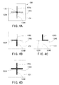
- FIGs. 4A to 4D show a cross phoria test chart with a fixation target for a phoria test.
- a cross phoria test chart 130 with a fixation target shown in Fig. 4A comprises a white background 131, a fixation target 132 defining a black optotype located in the center of the background 131, a left-side horizontal line 133R defining a red optotype, a lower-side vertical line 134R defining a red optotype, an upper-side vertical line 135G defining a green optotype, and a right-side horizontal line 136G defining a green optotype.
- Fig. 4B shows a state when the phoria test chart 130 is observed through the green filter 30G.
- the background 131 is visually perceived in green because green light therefrom is transmitted through the green filter 30G.
- the upper-side vertical line 135G and the right-side horizontal line 136G are visually perceived in green because green light therefrom is transmitted through the green filter 30G.
- the upper-side vertical line 135G and the right-side horizontal line 136G merge with the background 131, so that their shapes cannot be recognized.
- the left-side horizontal line 133R and the lower-side vertical line 134R are visually perceived in black because red light therefrom cannot be transmitted through the green filter 30G.
- Fig. 4C shows a state when the test chart 130 is observed through the red filter 30R.
- the background 131 is visually perceived in red
- the left-side horizontal line 133R and the lower-side vertical line 134R merge with the background 131, so that their shapes cannot be recognized.
- the upper-side vertical line 135G and the right-side horizontal line 136G are visually perceived in black because green light therefrom cannot be transmitted through the red filter 30R.
- the black fixation target 132 which does not have either of a red component and a green component, is visually perceived in black in each of the states shown in Figs. 4B and 4C .
- the optotypes are visually perceived differently through the red filter 30R and the green filter 30G. Therefore, the phoria test can be performed on the eyes of an examinee by using the fixation target 132 as a fusion optotype.
- the optotypes are visually perceived in a state shown in Fig. 4D which is a superposition of the states shown in Figs. 4B and 4C .
- Fig. 4D which is a superposition of the states shown in Figs. 4B and 4C .
- horizontal phoria there is visually perceived a horizontal deviation between the upper-side vertical line 135G and the right-side horizontal line 136G, and the left-side horizontal line 133R and the lower-side vertical line 134R.
- the red-green binocular visual performance test chart as described above was observed through a red filter 30R and a green filter 30G used in a subjective refractive power measurement apparatus 60.
- the green optotypes 104 and 105 did not merge with the background 101 and were inadvertently visually perceived in light green.
- the left-side horizontal line 133R and lower-side vertical line 134R were visually perceived in brighter red than the background 131, and there was visually perceived a difference against the background 131.
- the upper-side vertical line 135G and the right-side horizontal line 136G were visually perceived not in black similar to the fixation target 132 but in black slightly including a green component. If the optotypes do not merge with the background (i.e., if the optotypes do not disappear) as described above, accuracy in the binocular visual performance test is impaired.
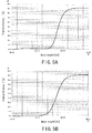
- Fig. 5A is a graph showing a result of checking a wavelength transmission characteristic of the red filter 30R used in the apparatus 60 with problems as described above.
- Fig. 5B is a graph showing a result of checking a wave length transmission characteristic of the red filter 30R used in the apparatus 60 with no problems.
- Fig. 6 is a graph showing a result of checking a characteristic of luminosity when the LCD 72 is controlled to emit only green light, and a characteristic of luminosity when the LCD 72 is controlled to emit only red light.
- Fig. 5B showing the wavelength transmission characteristic of the red filter 30R with no problems
- transmittance was constantly 0% in a wavelength range of 600 nm or less.
- Fig. 5A showing the wavelength transmission characteristic of the red filter 30R with problems
- light was slightly transmitted in a wavelength range of 550 to 600 nm.
- Fig. 6 showing the characteristic of luminosity in the green display of the LCD 72
- the peak of the characteristic of luminosity was in the vicinity of a wavelength of 550 nm and the characteristic of luminosity was even at a wavelength of about 600 nm. It is assumed that the green light was unintentionally transmitted through the red filter 30R with problems though slightly, so that the above result was obtained.
- green has a high characteristic of luminosity as compared to red (i.e., green is more easily perceived than red), which has an influence on the result.
- green filters 30G As for wavelength transmission characteristics of the green filter 30G, there was not observed any notable difference when the green filter 30G was used in the subjective refractive power measurement apparatus 60 or the red and green spectacles. However, green filters 30G also have various characteristics, and green filters 30G of different apparatus manufacturers could result in the same type of problem as the red filter 30R.
- the optotype presenting apparatus has a plurality of color adjustment data in which set values of the luminance levels of the RGB components (luminance and hue) of each of the optotypes constituting the binocular visual performance test chart to be displayed on the LCD 72 are set at a plurality of levels, and one of the color adjustment data is selected.
- switching is made between two stages of a High mode and a Low mode for selecting display colors of the binocular visual performance test chart.
- the High mode is intended for the red filter 30R having the wavelength transmission characteristic shown in Fig. 5B (i.e., the red filter with no problems) and the Low mode is intended for the red filter 30R having the wavelength transmission characteristic shown in Fig. 5A (i.e., the red filter with problems).
- a selection signal for selecting either of the High mode and the Low mode is inputted by operation of the switches of the function switch 73.
- the luminance levels of the RGB components (the color adjustment data) of each of the optotypes are set as follows. It should be noted that the RGB components of each of the optotypes to be displayed on the LCD 72 are arranged so that their luminance levels can be varied from the level 0 to the level 31 as described above.
- the level 31 is the highest level.
- the luminance levels of the RGB components of each of the optotypes differ according to the types of test chart, for example, differ between the Worth four-point test chart shown in Fig. 3A in which the red and green optotypes are provided on the black background and the cross phoria test chart shown in Fig. 4A in which the red and green optotypes are provided on the white background.
- the luminance levels of the RGB components of the green optotype are lowered, so that green light which could be unintentionally transmitted through the red filter 30R of Fig. 5A is decreased, and the green optotype can easily merge with the background.
- the luminance levels of the RGB components of the white optotype are also lowered in accordance with the lowering of the luminance levels of the RGB components of the green optotype.
- the luminance levels of the RGB components of the red optotype are lowered.
- the red optotype when the red optotype is displayed, not only the R (red) component but also the G (green) and B (blue) components are varied in their luminance levels in order to vary a hue (color tones: combination of the RGB components) of the display.
- all of the luminance levels of the RGB components of each of the white background and the white optotype are slightly lowered. Accordingly, when the red optotype is observed through the red filter 30R having the wavelength transmission characteristic shown in Fig. 5A , the red optotype can easily merge with the background which is visually perceived in red.
- the balance between the red optotype and the green optotype is obtained by slightly lowering the luminance levels of the RGB components of the green optotype in accordance with the red optotype becoming visually perceived in lighter red.
- the set values of the luminance levels of the RGB components (the color adjustment data) of each of the optotypes in the High mode and the Low mode as described above are previously stored in the memory 76.
- Fig. 7 is a table showing a list of test charts subjected to switching between the High mode and the Low mode.
- Examples of the binocular visual performance test chart subjected to switching between the High mode and the Low mode include the test charts as described above, a cross phoria test chart with no fixation target, an aniseikonia test chart, a cross-ring test chart for a phoria test, a cyclophoria test chart, and a stereoscopic vision test chart.
- the test charts subjected to switching between the High mode and the Low mode are assigned a value 1
- the test charts not subjected to switching are assigned a value 0, and the assigned values are stored in the memory 76.
- the stereoscopic vision test chart is set to be the white background type.
- the test chart with the red and green displays includes a red-green test chart 140 for testing overcorrection at the time of a refractive power test as shown in Fig. 8 .
- the red-green test chart 140 comprises a left-side red background 141R, a black optotype 142a consisting of letters and symbols provided on the left-side red background 141R, a right-side green background 141G, and a black optotype 142b consisting of letters and symbols provided on the right-side green background 141G.
- the test using the test chart 140 saturation of the black optotype 142a on the red background 141R and saturation of the black optotype 142b on the green background 141G are compared, and an overcorrection test is performed by checking whether or not both of them are similarly visually perceived.
- the red-green test chart 140 includes the red and green optotypes, the test using the red-green test chart 140 is not subjected to switching between the High mode and the Low mode of the luminance levels (hue) of the RGB components of each of the optotypes because it is performed without using the red filter 30R and the green filter 30G.
- predetermined set values of the luminance levels of the RGB components of the display colors are previously stored in the memory 76, are read by the control unit 75, and are displayed on the LCD 72.
- a polarized red-green test chart is the same type of test chart.
- predetermined set values of the luminance levels of the RGB components of the display colors of the LCD 72 are previously stored in the memory 76.
- the luminance levels of the RGB components (color adjustment data) of the red-green test chart 140 are set as follows.
- the visual acuity test chart comprises a Landolt ring black optotype on a white background (see Fig. 1 ).
- a parameter setting screen 80 is displayed on the LCD 72 as shown in Fig. 9 .
- the parameter setting screen 80 shows items 82 for setting various parameters of the apparatus.
- An operating key group 84 is displayed in the lower portion of the parameter setting screen 80.
- An UP key 84a corresponds to the switch 73a
- a DOWN key 84b corresponds to the switch 73b
- a CHANGE SCREEN key 84c corresponds to the switch 73c
- a CHANGE key 84d corresponds to the switch 73d.
- a cursor 81a is moved to the item "Brightness R/G", and the CHANGE key 84d is pressed to change the indication to "LOW”. Then, by operation of the DOWN key 84b, the cursor 81a is moved to an "EXIT" key 83, and the CHANGE key 84d is pressed to exit the setting screen, which completes changing the settings to the Low mode. Accordingly, a plurality of binocular visual performance test charts are switched altogether to the Low mode.
- the red filter 30R and/or the green filter 30G do not require being switched to the Low mode, they are used in the High mode.
- the High mode for example in the test chart 100 shown in Fig. 3A , the optotypes 102 and 103 are visually perceived in bright red when observed through the red filter 30R, and the optotypes 104 and 105 and the optotype 103 are visually perceived in bright green when observed through the green filter 30G, so that the difference between them becomes clear. Thus, accuracy of the test is improved.
- the selection signal is inputted to the control unit 75 via the transmitting portion 4c and the receiving unit 74.
- the control unit 75 reads the configuration data and the color adjustment data of the selected test chart from the memory 76 based on the selection signal of the test chart. If the binocular visual performance test chart is selected as the test chart, the control unit 75 reads, additionally based on the selection signal of the High mode or the Low mode, the color adjustment data corresponding to the selected mode from the memory 76. Then, the control unit 75 controls the LCD 72 to display the test chart based on the read configuration data and color adjustment data of the test chart.
- the control unit 75 reads predetermined color adjustment data corresponding to the selected test chart from the memory 76, and controls the LCD 72 to display the selected test chart.
- a confirmation screen 90a for a white background (hereinafter, referred to as a confirmation screen (white) 90a) shown in Fig. 10A or a confirmation screen 90b for a black background (hereinafter, referred to as a confirmation screen (black) 90b) shown in Fig. 10B is displayed.
- a Low mode setting screen 85 is displayed on each of the confirmation screen (white) 90a and the confirmation screen (black) 90b. Which of the confirmation screen (white) 90a and the confirmation screen (black) 90b is to be displayed is determined according to the position of a cursor 81b on the Low mode setting screen 85.
- the Low mode setting screen 85 comprises a condition setting screen 85a for a white background (hereinafter, referred to as a setting screen (white) 85a) and a condition setting screen 85b for a black background (hereinafter, referred to as a setting screen (black) 85b).
- a text display 86 indicating the background color is provided in the upper potion of each of the setting screen (white) 85aandthesettingscreen (black) 85b.
- Condition setting items 87a and 87b for selecting colors of the optotypes are provided on the setting screen (white) 85a and the setting screen (black) 85b, and the luminance levels of the RGB components of each of the optotypes can be set by using the items.
- any one of the RGB components next to the items 87a and 87b is selected by moving the cursor 81b by operation of the switch 73a corresponding to an UP key 89a for moving the cursor 81b to the next position and the switch 73b corresponding to a DOWN key 89b for moving the cursor 81b to the previous position. Then, the luminance levels are adjusted to be desired values by operation of the switch 73c corresponding to a plus key 89c and the switch 73d corresponding to a minus key 89d.
- the examiner checks visibility of a red screen 91a, a green screen 92a, a white screen 93a, and a black screen 94a through the red filter 30R and/or the green filter 30G.
- the confirmation screen (black) 90b shown in Fig. 10B the examiner checks visibility of a red screen 91b, a green screen 92b, a black screen 93b, and a white screen 94b through the red filter 30R and/or the green filter 30G.
- the luminance levels are inputted again as described above, and visibility is checked again through the red filter 30R and/or the green filter 30G.
- the switch 73c is pressed for a while and the settings are stored. Then, the cursor 81b is moved to an "EXIT" key 95, and the switch 73d is pressed in order to exit the setting screen.
- the examiner can perform color adjustment of such as luminance and hue while checking visibility of the red optotype and/or the green optotype through the red filter 30R and/or the green filter 30G. Therefore, the binocular visual performance test chart can be changed so as to have proper visibility in accordance with different characteristics of the red filter 30R and/or the green filter 30G.
- not only the two stages of the High mode and the Low mode but also three stages of High/Middle/Low modes or five stages from 5 to 1 in accordance with the degree of luminance may be used so that a plurality of luminance conditions may be stored for each of the items.
- set values which are changed for each test chart by the examiner may be stored.
- the color adjustment data such as the luminance levels of the RGB components of the test chart may be varied according to the environment where the optotype presenting apparatus is placed. For example, brightness of red and brightness of green are visually perceived differently in a bright room and a dark room; therefore, the color adjustment data of such as luminance and hue of the binocular visual performance test chart is accordingly changed. It is convenient to provide a brightness detecting sensor and arrange the control unit 75 to change the display colors of the LCD 72 based on the detected brightness.
Landscapes
- Life Sciences & Earth Sciences (AREA)
- Health & Medical Sciences (AREA)
- Medical Informatics (AREA)
- Biophysics (AREA)
- Ophthalmology & Optometry (AREA)
- Engineering & Computer Science (AREA)
- Biomedical Technology (AREA)
- Heart & Thoracic Surgery (AREA)
- Physics & Mathematics (AREA)
- Molecular Biology (AREA)
- Surgery (AREA)
- Animal Behavior & Ethology (AREA)
- General Health & Medical Sciences (AREA)
- Public Health (AREA)
- Veterinary Medicine (AREA)
- Eye Examination Apparatus (AREA)
Applications Claiming Priority (1)
| Application Number | Priority Date | Filing Date | Title |
|---|---|---|---|
| JP2007258167A JP5165326B2 (ja) | 2007-10-01 | 2007-10-01 | 視標呈示装置 |
Publications (3)
| Publication Number | Publication Date |
|---|---|
| EP2044878A2 true EP2044878A2 (de) | 2009-04-08 |
| EP2044878A3 EP2044878A3 (de) | 2010-07-28 |
| EP2044878B1 EP2044878B1 (de) | 2015-05-20 |
Family
ID=39925013
Family Applications (1)
| Application Number | Title | Priority Date | Filing Date |
|---|---|---|---|
| EP20080165166 Ceased EP2044878B1 (de) | 2007-10-01 | 2008-09-25 | Vorrichtung zur Darstellung von Optotypen |
Country Status (5)
| Country | Link |
|---|---|
| US (1) | US8087781B2 (de) |
| EP (1) | EP2044878B1 (de) |
| JP (1) | JP5165326B2 (de) |
| KR (1) | KR101466990B1 (de) |
| CN (1) | CN101401721B (de) |
Families Citing this family (19)
| Publication number | Priority date | Publication date | Assignee | Title |
|---|---|---|---|---|
| US8534839B2 (en) | 2010-03-01 | 2013-09-17 | Alcon Research, Ltd. | Adaptive visual performance testing system |
| US20120249951A1 (en) * | 2011-03-31 | 2012-10-04 | Nidek Co., Ltd. | Optotype presenting apparatus |
| US20170209041A1 (en) * | 2013-04-17 | 2017-07-27 | Kazuo Ichikawa | Color-viewing function measuring means and color-viewing function measurement system |
| WO2015179539A1 (en) * | 2014-05-20 | 2015-11-26 | The Schepens Eye Research Institute, Inc. | Quantification of inter-ocular suppression in binocular vision impairment |
| US20160352974A1 (en) * | 2015-05-27 | 2016-12-01 | Allan N. Hytowitz | Using Comparative Pixel and Luminance Adjustment for Creating a Varying Acuity Perception |
| KR101652739B1 (ko) * | 2016-03-23 | 2016-08-31 | (주) 뷰엠테크놀로지 | 시력 검사 방법, 시력 검사기 및 이 시력 검사 방법의 프로그램을 저장하는 다운로더 서버 |
| IL264531B2 (en) * | 2016-07-29 | 2023-10-01 | Medicontur Medical Eng Ltd | Measuring visual acuity of a person |
| WO2018050297A1 (en) * | 2016-09-14 | 2018-03-22 | Essilor International | Systems and methods for vision testing |
| US10016128B2 (en) * | 2016-09-27 | 2018-07-10 | David Evans | Method and apparatus for vision acuity testing |
| JP2018050975A (ja) * | 2016-09-29 | 2018-04-05 | 株式会社トプコン | 眼科装置 |
| KR101715577B1 (ko) * | 2016-11-09 | 2017-03-10 | 박준철 | 썬글라스 색상선정장치 |
| CN106510612B (zh) * | 2016-11-29 | 2018-06-29 | 河南科技大学 | 一种单眼伪盲自动检测装置 |
| US11291362B2 (en) * | 2017-11-01 | 2022-04-05 | Robert Wendell Arnold | Systems and methods for eye evaluation and treatment |
| CN110604542B (zh) * | 2019-10-23 | 2021-12-14 | 重庆能能科技有限公司 | 视觉抑制判定方法及其系统 |
| CN110967868A (zh) * | 2019-11-29 | 2020-04-07 | 纳晶科技股份有限公司 | 液晶显示终端及视力测试方法 |
| IL298146B2 (en) * | 2020-09-24 | 2025-03-01 | Shamir Optical Ind Ltd | System and method for assessing the visual ability of a subject |
| GB2609236A (en) * | 2021-07-26 | 2023-02-01 | Univ Strathclyde | Testing system |
| CN116211235B (zh) * | 2023-04-06 | 2023-09-19 | 江苏鸿晨集团有限公司 | 一种不等像视标 |
| US12582310B1 (en) | 2024-11-25 | 2026-03-24 | Dr Rp Holdings, Llc | Telescopic ocular refraction test apparatus, system, and method |
Citations (3)
| Publication number | Priority date | Publication date | Assignee | Title |
|---|---|---|---|---|
| JPH05130975A (ja) | 1991-05-08 | 1993-05-28 | Carl Zeiss:Fa | 視力検査装置 |
| US5638082A (en) | 1992-10-23 | 1997-06-10 | Carl-Zeiss Stiftung | Vision testing system for stereoscopic viewing by a test person |
| JP2006042978A (ja) | 2004-08-02 | 2006-02-16 | Nidek Co Ltd | 検眼装置 |
Family Cites Families (13)
| Publication number | Priority date | Publication date | Assignee | Title |
|---|---|---|---|---|
| JPS6417621A (en) * | 1987-07-13 | 1989-01-20 | Toshiba Corp | Electronic endoscopic apparatus |
| WO1995010219A1 (en) | 1992-06-08 | 1995-04-20 | Harper Gilberto B | Quantitative assessment of human ocular coordination |
| AUPQ842800A0 (en) * | 2000-06-28 | 2000-07-20 | Aivision Pty Ltd | Flat screen vision testing |
| US6379007B1 (en) * | 2000-10-23 | 2002-04-30 | Mark Daniel Farb | Eye chart with distinct symbols and methods for vision testing |
| JP2002224034A (ja) * | 2001-02-07 | 2002-08-13 | Topcon Corp | 自覚式検眼装置 |
| WO2002076301A1 (en) * | 2001-03-21 | 2002-10-03 | Marino Joseph A | Apparatus and method for testing visual acuity and fixation control |
| JP2004057741A (ja) * | 2002-07-31 | 2004-02-26 | Nidek Co Ltd | 検眼装置 |
| US6808267B2 (en) | 2002-10-18 | 2004-10-26 | Childsplay Vision Systems | Method for automated mass screening for visual dysfunction in children |
| JP2007190113A (ja) * | 2006-01-18 | 2007-08-02 | Sharp Corp | 映像出力装置 |
| WO2007109760A2 (en) | 2006-03-22 | 2007-09-27 | The Curators Of The University Of Missouri | Apparatus and method for assessing visual suppression |
| JP4827602B2 (ja) | 2006-04-28 | 2011-11-30 | 株式会社ニデック | 視標呈示装置 |
| JP4907240B2 (ja) | 2006-06-29 | 2012-03-28 | 株式会社ニデック | 視標呈示装置 |
| JP5026011B2 (ja) | 2006-07-21 | 2012-09-12 | 株式会社ニデック | 視標呈示装置 |
-
2007
- 2007-10-01 JP JP2007258167A patent/JP5165326B2/ja not_active Expired - Fee Related
-
2008
- 2008-09-24 US US12/232,797 patent/US8087781B2/en not_active Expired - Fee Related
- 2008-09-24 KR KR1020080093677A patent/KR101466990B1/ko not_active Expired - Fee Related
- 2008-09-25 EP EP20080165166 patent/EP2044878B1/de not_active Ceased
- 2008-09-27 CN CN2008101680859A patent/CN101401721B/zh not_active Expired - Fee Related
Patent Citations (3)
| Publication number | Priority date | Publication date | Assignee | Title |
|---|---|---|---|---|
| JPH05130975A (ja) | 1991-05-08 | 1993-05-28 | Carl Zeiss:Fa | 視力検査装置 |
| US5638082A (en) | 1992-10-23 | 1997-06-10 | Carl-Zeiss Stiftung | Vision testing system for stereoscopic viewing by a test person |
| JP2006042978A (ja) | 2004-08-02 | 2006-02-16 | Nidek Co Ltd | 検眼装置 |
Also Published As
| Publication number | Publication date |
|---|---|
| EP2044878B1 (de) | 2015-05-20 |
| EP2044878A3 (de) | 2010-07-28 |
| JP2009082573A (ja) | 2009-04-23 |
| JP5165326B2 (ja) | 2013-03-21 |
| CN101401721B (zh) | 2012-10-03 |
| CN101401721A (zh) | 2009-04-08 |
| US8087781B2 (en) | 2012-01-03 |
| KR101466990B1 (ko) | 2014-12-01 |
| US20090086166A1 (en) | 2009-04-02 |
| KR20090033794A (ko) | 2009-04-06 |
Similar Documents
| Publication | Publication Date | Title |
|---|---|---|
| EP2044878B1 (de) | Vorrichtung zur Darstellung von Optotypen | |
| EP2014221B1 (de) | Sehtestmuster-indikator | |
| EP1961373B1 (de) | Vorrichtung zur Darstellung von Optotypen | |
| EP1880663B1 (de) | Vorrichtung zur Darstellung von Optotypen | |
| US7819524B2 (en) | Optotype presenting apparatus | |
| US9149185B2 (en) | Functional vision tester | |
| US20070013870A1 (en) | Ophthalmic testing unit and ophthalmic testing equipment | |
| US9788715B2 (en) | Optotype presenting apparatus | |
| Walraven | The colours are not on the display: a survey of non-veridical perceptions that may turn up on a colour display | |
| JP2013081593A (ja) | 視標呈示装置 | |
| US7438417B2 (en) | Ophthalmic diagnostic apparatus for different types of tests | |
| JPH08140934A (ja) | 検眼装置 | |
| WO2025187223A1 (ja) | 視覚検査方法、視覚検査システム、および、視覚検査プログラム | |
| WO2025083436A1 (en) | Computer implemented color vision test | |
| CN121867674A (zh) | 一种色盲检测方法及头戴设备 | |
| WO2005091850A2 (en) | Apparatus and method for measuring differences in the transmission of light through a lens of an eye |
Legal Events
| Date | Code | Title | Description |
|---|---|---|---|
| PUAI | Public reference made under article 153(3) epc to a published international application that has entered the european phase |
Free format text: ORIGINAL CODE: 0009012 |
|
| AK | Designated contracting states |
Kind code of ref document: A2 Designated state(s): AT BE BG CH CY CZ DE DK EE ES FI FR GB GR HR HU IE IS IT LI LT LU LV MC MT NL NO PL PT RO SE SI SK TR |
|
| AX | Request for extension of the european patent |
Extension state: AL BA MK RS |
|
| PUAL | Search report despatched |
Free format text: ORIGINAL CODE: 0009013 |
|
| AK | Designated contracting states |
Kind code of ref document: A3 Designated state(s): AT BE BG CH CY CZ DE DK EE ES FI FR GB GR HR HU IE IS IT LI LT LU LV MC MT NL NO PL PT RO SE SI SK TR |
|
| AX | Request for extension of the european patent |
Extension state: AL BA MK RS |
|
| RIC1 | Information provided on ipc code assigned before grant |
Ipc: A61B 3/08 20060101ALI20100624BHEP Ipc: A61B 3/032 20060101AFI20081111BHEP Ipc: A61B 3/06 20060101ALI20100624BHEP |
|
| 17P | Request for examination filed |
Effective date: 20110119 |
|
| AKX | Designation fees paid |
Designated state(s): DE FR GB |
|
| 17Q | First examination report despatched |
Effective date: 20110517 |
|
| GRAP | Despatch of communication of intention to grant a patent |
Free format text: ORIGINAL CODE: EPIDOSNIGR1 |
|
| INTG | Intention to grant announced |
Effective date: 20141203 |
|
| GRAS | Grant fee paid |
Free format text: ORIGINAL CODE: EPIDOSNIGR3 |
|
| GRAA | (expected) grant |
Free format text: ORIGINAL CODE: 0009210 |
|
| AK | Designated contracting states |
Kind code of ref document: B1 Designated state(s): DE FR GB |
|
| REG | Reference to a national code |
Ref country code: GB Ref legal event code: FG4D |
|
| REG | Reference to a national code |
Ref country code: DE Ref legal event code: R096 Ref document number: 602008038204 Country of ref document: DE Effective date: 20150625 |
|
| REG | Reference to a national code |
Ref country code: DE Ref legal event code: R097 Ref document number: 602008038204 Country of ref document: DE |
|
| PLBE | No opposition filed within time limit |
Free format text: ORIGINAL CODE: 0009261 |
|
| STAA | Information on the status of an ep patent application or granted ep patent |
Free format text: STATUS: NO OPPOSITION FILED WITHIN TIME LIMIT |
|
| 26N | No opposition filed |
Effective date: 20160223 |
|
| REG | Reference to a national code |
Ref country code: FR Ref legal event code: PLFP Year of fee payment: 9 |
|
| REG | Reference to a national code |
Ref country code: FR Ref legal event code: PLFP Year of fee payment: 10 |
|
| REG | Reference to a national code |
Ref country code: FR Ref legal event code: PLFP Year of fee payment: 11 |
|
| PGFP | Annual fee paid to national office [announced via postgrant information from national office to epo] |
Ref country code: DE Payment date: 20210818 Year of fee payment: 14 Ref country code: GB Payment date: 20210818 Year of fee payment: 14 |
|
| PGFP | Annual fee paid to national office [announced via postgrant information from national office to epo] |
Ref country code: FR Payment date: 20220808 Year of fee payment: 15 |
|
| REG | Reference to a national code |
Ref country code: DE Ref legal event code: R119 Ref document number: 602008038204 Country of ref document: DE |
|
| GBPC | Gb: european patent ceased through non-payment of renewal fee |
Effective date: 20220925 |
|
| P01 | Opt-out of the competence of the unified patent court (upc) registered |
Effective date: 20230509 |
|
| PG25 | Lapsed in a contracting state [announced via postgrant information from national office to epo] |
Ref country code: DE Free format text: LAPSE BECAUSE OF NON-PAYMENT OF DUE FEES Effective date: 20230401 |
|
| PG25 | Lapsed in a contracting state [announced via postgrant information from national office to epo] |
Ref country code: GB Free format text: LAPSE BECAUSE OF NON-PAYMENT OF DUE FEES Effective date: 20220925 |
|
| PG25 | Lapsed in a contracting state [announced via postgrant information from national office to epo] |
Ref country code: FR Free format text: LAPSE BECAUSE OF NON-PAYMENT OF DUE FEES Effective date: 20230930 |