EP2045053A2 - Machine de découpe à disques pour aliments en forme de tronçons - Google Patents
Machine de découpe à disques pour aliments en forme de tronçons Download PDFInfo
- Publication number
- EP2045053A2 EP2045053A2 EP08016672A EP08016672A EP2045053A2 EP 2045053 A2 EP2045053 A2 EP 2045053A2 EP 08016672 A EP08016672 A EP 08016672A EP 08016672 A EP08016672 A EP 08016672A EP 2045053 A2 EP2045053 A2 EP 2045053A2
- Authority
- EP
- European Patent Office
- Prior art keywords
- machine according
- conveying direction
- transport slide
- food
- drive belt
- Prior art date
- Legal status (The legal status is an assumption and is not a legal conclusion. Google has not performed a legal analysis and makes no representation as to the accuracy of the status listed.)
- Granted
Links
- 238000005520 cutting process Methods 0.000 title claims abstract description 73
- 235000013305 food Nutrition 0.000 title claims abstract description 50
- 235000008429 bread Nutrition 0.000 claims description 22
- 210000000078 claw Anatomy 0.000 claims description 11
- 238000000034 method Methods 0.000 claims description 4
- 235000013351 cheese Nutrition 0.000 claims description 2
- 230000008901 benefit Effects 0.000 description 4
- 230000000694 effects Effects 0.000 description 3
- 239000000470 constituent Substances 0.000 description 1
- 125000004122 cyclic group Chemical group 0.000 description 1
- 238000006073 displacement reaction Methods 0.000 description 1
- 238000012423 maintenance Methods 0.000 description 1
- 230000000630 rising effect Effects 0.000 description 1
- 239000007787 solid Substances 0.000 description 1
Images

Classifications
-
- B—PERFORMING OPERATIONS; TRANSPORTING
- B26—HAND CUTTING TOOLS; CUTTING; SEVERING
- B26D—CUTTING; DETAILS COMMON TO MACHINES FOR PERFORATING, PUNCHING, CUTTING-OUT, STAMPING-OUT OR SEVERING
- B26D7/00—Details of apparatus for cutting, cutting-out, stamping-out, punching, perforating, or severing by means other than cutting
- B26D7/06—Arrangements for feeding or delivering work of other than sheet, web, or filamentary form
- B26D7/0683—Arrangements for feeding or delivering work of other than sheet, web, or filamentary form specially adapted for elongated articles
-
- B—PERFORMING OPERATIONS; TRANSPORTING
- B26—HAND CUTTING TOOLS; CUTTING; SEVERING
- B26D—CUTTING; DETAILS COMMON TO MACHINES FOR PERFORATING, PUNCHING, CUTTING-OUT, STAMPING-OUT OR SEVERING
- B26D1/00—Cutting through work characterised by the nature or movement of the cutting member or particular materials not otherwise provided for; Apparatus or machines therefor; Cutting members therefor
- B26D1/01—Cutting through work characterised by the nature or movement of the cutting member or particular materials not otherwise provided for; Apparatus or machines therefor; Cutting members therefor involving a cutting member which does not travel with the work
- B26D1/12—Cutting through work characterised by the nature or movement of the cutting member or particular materials not otherwise provided for; Apparatus or machines therefor; Cutting members therefor involving a cutting member which does not travel with the work having a cutting member moving about an axis
- B26D1/14—Cutting through work characterised by the nature or movement of the cutting member or particular materials not otherwise provided for; Apparatus or machines therefor; Cutting members therefor involving a cutting member which does not travel with the work having a cutting member moving about an axis with a circular cutting member, e.g. disc cutter
- B26D1/157—Cutting through work characterised by the nature or movement of the cutting member or particular materials not otherwise provided for; Apparatus or machines therefor; Cutting members therefor involving a cutting member which does not travel with the work having a cutting member moving about an axis with a circular cutting member, e.g. disc cutter rotating about a movable axis
- B26D1/16—Cutting through work characterised by the nature or movement of the cutting member or particular materials not otherwise provided for; Apparatus or machines therefor; Cutting members therefor involving a cutting member which does not travel with the work having a cutting member moving about an axis with a circular cutting member, e.g. disc cutter rotating about a movable axis mounted on a movable arm or the like
-
- B—PERFORMING OPERATIONS; TRANSPORTING
- B26—HAND CUTTING TOOLS; CUTTING; SEVERING
- B26D—CUTTING; DETAILS COMMON TO MACHINES FOR PERFORATING, PUNCHING, CUTTING-OUT, STAMPING-OUT OR SEVERING
- B26D7/00—Details of apparatus for cutting, cutting-out, stamping-out, punching, perforating, or severing by means other than cutting
-
- B—PERFORMING OPERATIONS; TRANSPORTING
- B26—HAND CUTTING TOOLS; CUTTING; SEVERING
- B26D—CUTTING; DETAILS COMMON TO MACHINES FOR PERFORATING, PUNCHING, CUTTING-OUT, STAMPING-OUT OR SEVERING
- B26D7/00—Details of apparatus for cutting, cutting-out, stamping-out, punching, perforating, or severing by means other than cutting
- B26D7/01—Means for holding or positioning work
-
- B—PERFORMING OPERATIONS; TRANSPORTING
- B26—HAND CUTTING TOOLS; CUTTING; SEVERING
- B26D—CUTTING; DETAILS COMMON TO MACHINES FOR PERFORATING, PUNCHING, CUTTING-OUT, STAMPING-OUT OR SEVERING
- B26D7/00—Details of apparatus for cutting, cutting-out, stamping-out, punching, perforating, or severing by means other than cutting
- B26D7/06—Arrangements for feeding or delivering work of other than sheet, web, or filamentary form
- B26D7/0641—Arrangements for feeding or delivering work of other than sheet, web, or filamentary form using chutes, hoppers, magazines
-
- B—PERFORMING OPERATIONS; TRANSPORTING
- B26—HAND CUTTING TOOLS; CUTTING; SEVERING
- B26D—CUTTING; DETAILS COMMON TO MACHINES FOR PERFORATING, PUNCHING, CUTTING-OUT, STAMPING-OUT OR SEVERING
- B26D7/00—Details of apparatus for cutting, cutting-out, stamping-out, punching, perforating, or severing by means other than cutting
- B26D7/08—Means for treating work or cutting member to facilitate cutting
- B26D7/086—Means for treating work or cutting member to facilitate cutting by vibrating, e.g. ultrasonically
-
- B—PERFORMING OPERATIONS; TRANSPORTING
- B26—HAND CUTTING TOOLS; CUTTING; SEVERING
- B26D—CUTTING; DETAILS COMMON TO MACHINES FOR PERFORATING, PUNCHING, CUTTING-OUT, STAMPING-OUT OR SEVERING
- B26D7/00—Details of apparatus for cutting, cutting-out, stamping-out, punching, perforating, or severing by means other than cutting
- B26D7/18—Means for removing cut-out material or waste
-
- B—PERFORMING OPERATIONS; TRANSPORTING
- B26—HAND CUTTING TOOLS; CUTTING; SEVERING
- B26D—CUTTING; DETAILS COMMON TO MACHINES FOR PERFORATING, PUNCHING, CUTTING-OUT, STAMPING-OUT OR SEVERING
- B26D7/00—Details of apparatus for cutting, cutting-out, stamping-out, punching, perforating, or severing by means other than cutting
- B26D7/27—Means for performing other operations combined with cutting
- B26D7/32—Means for performing other operations combined with cutting for conveying or stacking cut product
-
- B—PERFORMING OPERATIONS; TRANSPORTING
- B26—HAND CUTTING TOOLS; CUTTING; SEVERING
- B26D—CUTTING; DETAILS COMMON TO MACHINES FOR PERFORATING, PUNCHING, CUTTING-OUT, STAMPING-OUT OR SEVERING
- B26D7/00—Details of apparatus for cutting, cutting-out, stamping-out, punching, perforating, or severing by means other than cutting
- B26D7/01—Means for holding or positioning work
- B26D2007/011—Means for holding or positioning work by clamping claws, e.g. in high speed slicers for food products
-
- B—PERFORMING OPERATIONS; TRANSPORTING
- B26—HAND CUTTING TOOLS; CUTTING; SEVERING
- B26D—CUTTING; DETAILS COMMON TO MACHINES FOR PERFORATING, PUNCHING, CUTTING-OUT, STAMPING-OUT OR SEVERING
- B26D7/00—Details of apparatus for cutting, cutting-out, stamping-out, punching, perforating, or severing by means other than cutting
- B26D7/27—Means for performing other operations combined with cutting
- B26D7/32—Means for performing other operations combined with cutting for conveying or stacking cut product
- B26D2007/327—Means for performing other operations combined with cutting for conveying or stacking cut product the cut products being slices of bread
Definitions
- the invention relates to a cutting machine with which bread, cheese and the like string-shaped food can be cut into any desired thicknesses by machine.
- this angular design of the bearing surfaces for the food to be cut does not prevent the respective cut slice from tilting laterally with respect to the food strand and being present at an angle to it after the cutting process. As a result, a scale-like abutment of the cut slices can not be completely prevented.
- the present invention seeks to provide a slicing machine of the type mentioned above, with the quality results can be achieved and is as simple as possible to the operator in their operation and maintenance.
- the invention provides that the bearing surface for the cut slices and the bearing surface for the not yet sliced food strand lie in a plane and are not kinked, but that the orientation of these two bearing surfaces obliquely in space, but with the same Tilt angle, is aligned.
- the cutting blade is aligned perpendicular to the two bearing surfaces. This inclined in the fall direction orientation of the bearing surfaces on which the strand-shaped food is supplied to the cutting device and on which it leaves the cutter in disc form, has the advantage that the respective cut disc is less affected by their cutting on the cutting blade, as if perpendicular would be aligned standing.
- the food strand when still moving in the direction of the cutting blade, the food strand, which is still in one piece, can press against the already cut slice to and through the entire surface. A mutual spatial, scale-like displacement between the not yet cut end side of the food strand and the already cut slices does not take place.
- the strand-shaped food is cut without offset downwards or sideways into slices, without losing the strand shape is lost.
- a further solution according to the invention for preventing the adhesion of cut disks to the cutting blade is inventively provided in that the bearing surface for the cut disks has an endlessly circulating conveyor belt.
- the above-mentioned relative movement between the cutting blade and cut slices can be effected according to a further solution according to the invention as follows.
- the transport slider which engages behind the food strand and moves the strand in the direction of the cutting blade, acts on the food strand in a manner that is resistant to tension and pressure.
- the food strand is passed cyclically through the cutting device and thus on the cutting blade accordingly.
- the pressure with which the food strand rests against the cutting blade and thus also the pressure with which it presses against the cut disks is reduced.
- a holding device for the sliced slices of the food strand can be provided.
- This holding device, against which the cut disk strand can lean, can be moved intermittently. This does not necessarily use the not yet sliced food strand to move the cut slices. As a result, the cut discs are subjected to a lower pressure load, which benefits the cut surface and thus the quality of the disc surface.
- the inclined orientation of the bearing surfaces for the sliced food to be sliced has the advantage that the cutting blade can be easily tilted.
- the axis of rotation of the cutting blade usually runs parallel to the bearing surfaces, so that the circular surface of the cutting blade and thus the axis slightly obliquely upwards extends an operator hunched into the machine very easy to use.
- This accessibility to the cutting device is still greatly facilitated thereby, and this is true in principle for all orientations of such a cutting device that the front wall of the cutting machine, that is, the front wall of the housing of this disc cutting machine is easily removable.
- the front wall of the housing of the corresponding disc cutting machine in the region of the bearing surfaces, in which the food is still present strandless uncut even be removed together with these bearing surfaces.
- These removed parts once consist of the front of the container for crumbs, which is regularly present in such slicing machines, and optionally also of a housing part which is integrally connected to the bearing surfaces in the region of the not yet cut strand-shaped food.
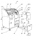
- slicing machine 10 is formed in the present example case for cutting bread in particular.
- the bread slicer 10 shown thereafter has an outer housing 12 with an approximately rectangular floor plan.
- the housing 12 rests on four double rollers 14, so that it can be easily moved back and forth.
- the bread slicer 10 can be closed by a sliding lid 16, which can be pushed back and forth by a handle 18 similar to a roller shutter.
- the sliding lid 16 is pushed back so that a bread can be inserted into the bread slicer 10 or the cut slices can be removed.
- the channel bottom 22 is only in his in Fig. 1 left area shown. In which - based on the Fig. 1 - Right area is this channel floor 22, the in Fig. 2 designated by the reference numeral 22.2, from the housing 12th taken out, as will be described later.
- the entire channel bottom 22 (22.2) is slightly inclined, so that the cut or to be cut food on the one hand on the channel bottom 22 (22.2) and on the other hand on the front channel wall 24 and 24.2 abuts.
- the angle of inclination 25 is preferably between 5 degrees and 50 degrees and in the present example case is approximately between 5 degrees and 15 degrees.
- Channel bottom and channel wall are aligned approximately at right angles to each other. This means that the channel wall 24, 24.2 is inclined into the interior of the housing 12 from the front side. Channel bottom and channel wall thus form a downward - in the present case at right angles - tapered V-shaped bearing surface on the one hand for not yet cut, still present as strand food, and on the other hand for the slices of the relevant food such as a bread.
- the channel bottom 22 and the front channel wall 24 are partially bounded on the front side of the housing 12 by a front wall 26.
- this front wall is not present.
- This right area of the front wall is composed of a right upper front wall 26.2 and a right lower front wall 26.3 (FIG. Fig. 2 ).
- the upper right front wall 26.2 has a bent shape and is flush with the also bent contour of the left front wall 26 at. At the upper edge 28 of the upper right front wall 26.2 is closed to the rear, in the housing 12, the already mentioned channel wall 24.2 with the integrally formed thereon channel bottom 22.2.
- the channel bottom 22.2 is aligned in the inserted state in the opening 30 of this upper right front wall 26.2 with the channel bottom 22.
- the channel wall 24.2 of the right upper front wall 26.2 is aligned with the front channel wall 24.
- In the inserted state of the channel bottom 22.2 and the channel wall 24.2 lie in one comparable V-shaped support 32 which extends transversely through the housing 12 from front to back. Between the support 32 and the (left) channel bottom 22, a slot 33 for the free movement of a circular blade 66 is formed.
- the upper right front wall 26.2 is in the inserted state, the housing 12 at the bottom of a cross bar 34 at.
- This cross bar 34 is present between the left front wall 26 and the right side wall 36 of the housing 12.
- Of the Cross bar 34 has a stop 38 on which the inserted upper right front wall 26.2 can be locked by means of a rotary handle 40 in its inserted state.
- the collecting container 42 has a left and right side wall 44, 46 and a rear side wall 48. These side walls frame together with the right lower front wall 26.3 a bottom 50 a.
- the side walls 44, 46, 48 are lower in the present example than the right lower front wall 26.3.
- the right side wall 46 connects flush with the right side wall 36 of the housing 12 from the inside.
- the left sidewall 44 adjoins the side of a center wall 52 which laterally defines the motor and electrical drive and control means provided behind the left front wall 26. With his on top, parallel to the footprint of the double rollers 14 aligned bottom 50 of the crumb collection container 42 is in the inserted state on the bottom 58 of the housing 12.
- a deflecting plate 54 (FIG. Fig. 1 ) or 56 ( Fig. 2 ), which ensure that crumbs resulting from cutting fall safely into the collecting container 42.
- a drive pulley 60 which pierces the central wall 52 with its central axis of rotation 62.
- this drive pulley 60 can be set in rotation.
- On the drive pulley 60 is mounted eccentrically, about a rotation axis 64 around, a circular blade 66.
- the circular blade 66 can be rotatably driven counterclockwise 68 in the present example case.
- the drive pulley 60 can also be rotated counterclockwise 70.
- the circular blade 66 moves around the axis of rotation 62 of the drive pulley 60 like a satellite.
- the circular blade 66 travels through the slot 84 adjacent to the support 32 as it moves.
- a support plate 90 is present in the region of the channel bottom 22, a support plate 90 is present. This can be driven by a motor drive along a rail-like guide 120 (FIG. Fig. 3 ) protected by a hood-like cover 88, are moved back and forth (double arrow 92). The support plate 90 is moved so that the one or more cut slices rest against it after cutting from the food strand and can not fall over the channel bottom 22. According to the cutting process, this support plate 90 is thereby in particular cyclically after - Fig. 1 - move left.
- the food strand for example a bread
- the transport slider 94 has a plurality of adjacent claws 96, which penetrate sufficiently sufficiently in the cutting process from above into the end of the food strand.
- the transport slide 94 located in Fig. 1 and 2 is located in its rear parking position, each time in a cutting operation in the direction of this parking position moves back a little way or that he is moved back and that he doing the food strand after - in Fig. 1 . 2 - takes a bit to the right.
- the circular blade 66 can be vibrated. Also, thereby adhering of the food can be prevented on both the transport slider 94 side facing as well as the support plate 90 side facing.
- the vibrating of the sliced bearing surface preferably starts after a predeterminable number of cut slices. It has been found that at least when cutting the first two discs, these bearing surfaces should not vibrate.
- this storage area By vibrating the bearing surface for the cut slices, it is possible to arrange this storage area also horizontally or even slightly rising, as it were uphill. As before, the inclination of this bearing surface may be the same as the inclination of the bearing surface of the feeder.
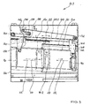
- Fig. 3 the drive means and guide means are shown, with which a food or a bread and its cut slices are transported in a disc cutting machine according to the invention.
- slicing machine 10.3 substantially corresponds to the disc cutting machine 10 described above. In this regard, the above statements expressly.
- the transport slide 94 of the disc cutting machine 10.3 is attached to a drive belt 104 via a support plate 102 with which it is firmly connected.
- a support plate 102 At the - related to the Fig. 3 - Bottom of the support plate 102 are not shown in the drawing guide rollers 106, 108 rotatably supported, by means of which it is along a rail-like guide 110 movable back and forth.
- the guide 110 is present parallel to the conveying direction 112 and thus also to the counter-conveying direction 114 behind the rear guide wall 20.
- a further rail-like guide 120 is present, which is aligned parallel to the guide 110 and laterally offset from the guide 110 is present.
- the drive belt 104 runs with a channel-side belt section 104.2 parallel to the conveying direction 112 or counter-conveying direction 114. At the end of this belt section 104.2, the drive belt 104 runs around two deflection rollers 130,132. The belt 104 is further guided around a tensioning roller 134 and around a motor-driven further deflection roller 136 endlessly.
- the support plate 102 of the transport slide 94 is mounted close to the region of the right deflection roller 132 fixed to the belt section 104.2.
- By motor driving the guide roller 136 can now by appropriate process of the drive belt 104 and thus also the belt section 104.2 of the transport slide 94 from his in Fig. 3 shown park position in front of him lying bread in the conveying direction 112 move.
- the bread may then be sliced by the circular knife 66, as previously described.
- the end position of the transport slide 94 is shown in phantom by the reference numeral 94.2. Between these positions 94, 94.2, the drive belt 104 is moved back and forth, as already described above.
- the support plate 90 is fixedly secured to a support plate 140.
- This support plate 140 is in turn firmly connected to a driver 142.
- a fixed to the driver 142 carriage 154 has not shown in the drawing guide rollers, with which it is guided along the rail-like guide 120 in the conveying direction 112 and in the counter-conveying direction 114 back and forth adjustably.
- the driver 142 has an electromagnetic claw 144, between the two claws of the belt portion 104.2 of the drive belt 104 is guided freely. By electromagnetic actuation, the claw 144 can be closed. It clamps the drive belt 104 firmly between them. In this way, the driver 142 and thus ultimately the support plate 90 can be firmly attached to the drive belt 104.
- the support plate 90 can move uniformly with the transport slide 94 in the conveying direction 112 with.
- the support plate 90 is at a predetermined, close distance to the circular blade 66, that has been moved to the right and not in their in Fig. 3 drawn solid left position. If when starting the drive belt 104, the claw 144 is closed and the support plate 90 moves as a result synchronously with the transport slide 94 in the conveying direction 112, the support plate 90 is not in their in Fig. 3 shown left end position.
- a limit switch which may be located for example in the area between the support plate 90 and the left side wall 150, it is ensured that when abutment of the support plate 90 or the support plate 140 or other firmly connected to the support plate 90 part of this limit switch, the not shown in the drawing, the electromotive drive of the guide roller 136 is stopped. Comparable can also be achieved if by appropriate limit - the - related to the Fig. 3 - Right start area of the support plate 90 is monitored.
Landscapes
- Life Sciences & Earth Sciences (AREA)
- Forests & Forestry (AREA)
- Engineering & Computer Science (AREA)
- Mechanical Engineering (AREA)
- Food-Manufacturing Devices (AREA)
- Formation And Processing Of Food Products (AREA)
Applications Claiming Priority (2)
| Application Number | Priority Date | Filing Date | Title |
|---|---|---|---|
| DE202007013728 | 2007-10-01 | ||
| DE202008003603U DE202008003603U1 (de) | 2007-10-01 | 2008-03-14 | Scheibenschneidmaschine für strangförmige Lebensmittel |
Publications (3)
| Publication Number | Publication Date |
|---|---|
| EP2045053A2 true EP2045053A2 (fr) | 2009-04-08 |
| EP2045053A3 EP2045053A3 (fr) | 2009-06-24 |
| EP2045053B1 EP2045053B1 (fr) | 2010-11-03 |
Family
ID=39400332
Family Applications (1)
| Application Number | Title | Priority Date | Filing Date |
|---|---|---|---|
| EP20080016672 Not-in-force EP2045053B1 (fr) | 2007-10-01 | 2008-09-23 | Machine de découpe à disques pour aliments en forme de tronçons |
Country Status (2)
| Country | Link |
|---|---|
| EP (1) | EP2045053B1 (fr) |
| DE (2) | DE202008003603U1 (fr) |
Cited By (17)
| Publication number | Priority date | Publication date | Assignee | Title |
|---|---|---|---|---|
| DE102010045823A1 (de) | 2010-09-20 | 2012-03-22 | Rudi Siller | Scheibenschneidmaschine für strangförmige Lebensmittel |
| DE102013001847A1 (de) | 2013-02-04 | 2014-08-07 | Rudi Siller | Schneidmaschine für strangförmige Lebensmittel |
| DE102014000297A1 (de) | 2013-12-18 | 2015-06-18 | Rudi Siller | Schneidmaschine für strangförmige Lebensmittel |
| EP2937191A1 (fr) | 2014-04-24 | 2015-10-28 | MHS Schneidetechnik GmbH | MACHINE DE DÉCOUPE DE PRODUITS ALIMENTAIRES DE FORME ALLONGéE |
| DE102014007065A1 (de) | 2014-05-15 | 2015-11-19 | Mhs Schneidetechnik Gmbh | Schneidmaschine für Brot |
| DE202016001529U1 (de) | 2016-03-09 | 2017-06-12 | Mhs Schneidetechnik Gmbh | Schneidmaschine für strangförmige Lebensmittel |
| DE202017002742U1 (de) | 2017-05-24 | 2017-06-26 | Mhs Schneidetechnik Gmbh | Schneidmaschine für strangförmige Lebensmittel |
| US9895820B2 (en) | 2012-01-24 | 2018-02-20 | R. Weiss Verpackungstechnik Gmbh & Co. | Bread slicing machine having an advancing device |
| DE102016010635A1 (de) | 2016-09-05 | 2018-03-08 | Mhs Schneidetechnik Gmbh | Schneidmaschine für strangförmige Lebensmittel |
| CN108453808A (zh) * | 2018-02-07 | 2018-08-28 | 海宁市鑫航塑料制品有限公司 | 一种塑料管切割用切割机 |
| CN109773864A (zh) * | 2019-01-31 | 2019-05-21 | 林飞飞 | 一种具有防尘功能的塑料加工设备 |
| EP3599067A1 (fr) | 2018-07-25 | 2020-01-29 | Siller Holding GmbH | Machine de découpe pour produits alimentaires en forme de tige |
| CN112792889A (zh) * | 2020-12-21 | 2021-05-14 | 邱强 | 一种食品加工用藕带切割设备 |
| EP3907051A1 (fr) | 2020-05-06 | 2021-11-10 | Jac S.A. | Trancheuse de pain oblique |
| DE102020007939A1 (de) | 2020-06-24 | 2021-12-30 | Siller Holding GmbH | Schneidmaschine für strangförmige Lebensmittel |
| EP4116049A1 (fr) | 2021-07-05 | 2023-01-11 | Jac S.A. | Trancheuse à pain avec une surface d'appui mobile pour le pain coupé |
| EP4458535A1 (fr) | 2023-05-02 | 2024-11-06 | Jac S.A. | Trancheuse de pain |
Families Citing this family (8)
| Publication number | Priority date | Publication date | Assignee | Title |
|---|---|---|---|---|
| DE102008002636A1 (de) * | 2008-06-25 | 2010-01-07 | Reifenhäuser, Uwe | Maschine zum Schneiden von Lebensmitteln |
| DE102008033922B4 (de) * | 2008-07-18 | 2012-11-08 | Claas Saulgau Gmbh | Häckselaggregat für Feldhäcksler |
| DE102010002279A1 (de) * | 2010-02-24 | 2011-08-25 | Reifenhäuser, Uwe, 57632 | Maschine zum Schneiden eines strangförmigen Lebensmittels |
| EP2754540B1 (fr) * | 2013-01-09 | 2016-04-06 | A O Schallinox GmbH | Procédé et dispositif de coupe d'aliments |
| DE202014000131U1 (de) | 2014-01-04 | 2014-02-14 | Uwe Schmidt | Vorrichtung zum Abdichten von in Transportrichtung verlaufenden, langlochförmigen Öffnungen in Brotschneidemaschinen |
| DE202019100509U1 (de) * | 2019-01-29 | 2020-05-28 | Tpv Gmbh | Brotschneidemaschine |
| EP3831558A1 (fr) * | 2019-12-05 | 2021-06-09 | Bizerba SE & Co. KG | Machine à couper le pain pourvue d'aide à la coupe ainsi que procédé de fonctionnement préférée |
| EP3831560A1 (fr) | 2019-12-05 | 2021-06-09 | Bizerba SE & Co. KG | Machine à couper le pain pourvue d'aide à l'emballage intégrée ainsi que procédé de fonctionnement préféré |
Citations (1)
| Publication number | Priority date | Publication date | Assignee | Title |
|---|---|---|---|---|
| DE19820004C2 (de) | 1998-05-06 | 2000-06-08 | Uwe Reifenhaeuser | Maschine zum Schneiden eines Gutsstrangs in Scheiben |
Family Cites Families (11)
| Publication number | Priority date | Publication date | Assignee | Title |
|---|---|---|---|---|
| US4662257A (en) * | 1984-11-30 | 1987-05-05 | Oliver Products Company | Countertop bread slicer |
| JPH07100317B2 (ja) * | 1990-03-07 | 1995-11-01 | 株式会社カイジョー | パン類、蓄肉加工品等の超音波切断装置及び切断装置 |
| GB2242117A (en) * | 1990-03-23 | 1991-09-25 | Apv Baker Pty Ltd | Bread slicing machine |
| DE9107225U1 (de) * | 1991-06-12 | 1991-09-19 | holac Maschinenbau GmbH, 89520 Heidenheim | Schneidemaschine für Lebensmittel |
| DE4142009A1 (de) * | 1991-12-19 | 1993-06-24 | Dixie Union Verpackungen Gmbh | Vorschubantrieb fuer schneidmaschinen |
| DE9313637U1 (de) * | 1993-09-09 | 1993-11-25 | MHS Schneidetechnik GmbH, 74223 Flein | Schneidmaschine für Brot |
| DE19856683A1 (de) * | 1998-12-09 | 2000-06-15 | Max Norbisrath | Vorrichtung zum An- und Durchschneiden von Brötchen |
| DE10312301B4 (de) * | 2003-03-20 | 2006-08-03 | Reifenhäuser, Uwe, Dipl.-Ing. | Brotschneidemaschine |
| DE102005010185A1 (de) * | 2005-03-02 | 2006-09-07 | Cfs Kempten Gmbh | Vorrichtung zum Aufschneiden von Lebensmittelprodukten |
| DE102005040336A1 (de) * | 2005-08-25 | 2007-03-01 | Weber Maschinenbau Gmbh & Co. Kg | Vorrichtung zum Aufschneiden von Lebensmittelprodukten |
| DE102005062501B4 (de) * | 2005-12-16 | 2009-10-22 | Bizerba Gmbh & Co. Kg | Lebensmittelschneidemaschine |
-
2008
- 2008-03-14 DE DE202008003603U patent/DE202008003603U1/de not_active Expired - Lifetime
- 2008-09-23 EP EP20080016672 patent/EP2045053B1/fr not_active Not-in-force
- 2008-09-23 DE DE200850001695 patent/DE502008001695D1/de active Active
Patent Citations (1)
| Publication number | Priority date | Publication date | Assignee | Title |
|---|---|---|---|---|
| DE19820004C2 (de) | 1998-05-06 | 2000-06-08 | Uwe Reifenhaeuser | Maschine zum Schneiden eines Gutsstrangs in Scheiben |
Cited By (27)
| Publication number | Priority date | Publication date | Assignee | Title |
|---|---|---|---|---|
| DE102010045823A1 (de) | 2010-09-20 | 2012-03-22 | Rudi Siller | Scheibenschneidmaschine für strangförmige Lebensmittel |
| US9895820B2 (en) | 2012-01-24 | 2018-02-20 | R. Weiss Verpackungstechnik Gmbh & Co. | Bread slicing machine having an advancing device |
| DE102013001847A1 (de) | 2013-02-04 | 2014-08-07 | Rudi Siller | Schneidmaschine für strangförmige Lebensmittel |
| EP2796252A2 (fr) | 2013-02-04 | 2014-10-29 | SILLER, Rudi | Machine de découpe pour produits alimentaires en forme de tige |
| EP2796252A3 (fr) * | 2013-02-04 | 2015-03-04 | SILLER, Rudi | Machine de découpe pour produits alimentaires en forme de tige |
| DE102014000297A1 (de) | 2013-12-18 | 2015-06-18 | Rudi Siller | Schneidmaschine für strangförmige Lebensmittel |
| EP2886269A1 (fr) | 2013-12-18 | 2015-06-24 | SILLER, Rudi | Machine de découpe pour produits alimentaires en forme de tige |
| EP2937191A1 (fr) | 2014-04-24 | 2015-10-28 | MHS Schneidetechnik GmbH | MACHINE DE DÉCOUPE DE PRODUITS ALIMENTAIRES DE FORME ALLONGéE |
| DE102014005813A1 (de) | 2014-04-24 | 2015-10-29 | Mhs Schneidetechnik Gmbh | Schneidmaschine für strangförmige Lebensmittel |
| DE102014007065A1 (de) | 2014-05-15 | 2015-11-19 | Mhs Schneidetechnik Gmbh | Schneidmaschine für Brot |
| DE202016001529U1 (de) | 2016-03-09 | 2017-06-12 | Mhs Schneidetechnik Gmbh | Schneidmaschine für strangförmige Lebensmittel |
| DE102016010635A1 (de) | 2016-09-05 | 2018-03-08 | Mhs Schneidetechnik Gmbh | Schneidmaschine für strangförmige Lebensmittel |
| DE202017002742U1 (de) | 2017-05-24 | 2017-06-26 | Mhs Schneidetechnik Gmbh | Schneidmaschine für strangförmige Lebensmittel |
| DE102018003556A1 (de) | 2017-05-24 | 2018-11-29 | Siller Holding GmbH | Schneidmaschine für strangförmige Lebensmittel |
| CN108453808A (zh) * | 2018-02-07 | 2018-08-28 | 海宁市鑫航塑料制品有限公司 | 一种塑料管切割用切割机 |
| EP3599067A1 (fr) | 2018-07-25 | 2020-01-29 | Siller Holding GmbH | Machine de découpe pour produits alimentaires en forme de tige |
| CN109773864A (zh) * | 2019-01-31 | 2019-05-21 | 林飞飞 | 一种具有防尘功能的塑料加工设备 |
| EP3907051A1 (fr) | 2020-05-06 | 2021-11-10 | Jac S.A. | Trancheuse de pain oblique |
| BE1028272A1 (fr) | 2020-05-06 | 2021-12-03 | Jac S A | Trancheuse de pain oblique |
| DE102020007939A1 (de) | 2020-06-24 | 2021-12-30 | Siller Holding GmbH | Schneidmaschine für strangförmige Lebensmittel |
| WO2021259407A1 (fr) | 2020-06-24 | 2021-12-30 | Siller Holding GmbH | Trancheuse pour produits alimentaires sous forme de bloc |
| CN112792889A (zh) * | 2020-12-21 | 2021-05-14 | 邱强 | 一种食品加工用藕带切割设备 |
| CN112792889B (zh) * | 2020-12-21 | 2023-08-25 | 南京茂升德科技有限公司 | 一种食品加工用藕带切割设备 |
| EP4116049A1 (fr) | 2021-07-05 | 2023-01-11 | Jac S.A. | Trancheuse à pain avec une surface d'appui mobile pour le pain coupé |
| BE1029561A1 (fr) | 2021-07-05 | 2023-01-30 | Jac S A | Trancheuse à pain avec une surface d’appui mobile pour le pain coupé |
| EP4458535A1 (fr) | 2023-05-02 | 2024-11-06 | Jac S.A. | Trancheuse de pain |
| BE1031571A1 (fr) | 2023-05-02 | 2024-12-02 | Jac S A | Trancheuse de pain |
Also Published As
| Publication number | Publication date |
|---|---|
| DE502008001695D1 (de) | 2010-12-16 |
| DE202008003603U1 (de) | 2008-05-15 |
| EP2045053B1 (fr) | 2010-11-03 |
| EP2045053A3 (fr) | 2009-06-24 |
Similar Documents
| Publication | Publication Date | Title |
|---|---|---|
| EP2045053B1 (fr) | Machine de découpe à disques pour aliments en forme de tronçons | |
| EP3102376B1 (fr) | Méthode de découpe et machine de découpe d'aliments en forme de boudin | |
| EP2359992B2 (fr) | Machine de coupe d'un aliment en forme de tronçon | |
| DE19518583A1 (de) | Schneidmaschine | |
| EP2226170B1 (fr) | Cadres de chaînes de guidage pour trancheuse d'aliments automatique | |
| DE102010036721A1 (de) | Verfahren zum Schneiden eines Brotlaibs sowie Brotschneidemaschine | |
| DE102011075132A1 (de) | Verfahren zum Verpacken von Scheibenpaketen aus Lebensmitteln in einer Schneidemaschine sowie Schneidemaschine hierfür | |
| EP2894016A1 (fr) | Dispositif et procédé pour la coupe de produits alimentaires | |
| EP2322330B1 (fr) | Procédé et dispositif de coupe d'un tronçon de viande contenant des os en tranches | |
| EP1094717A1 (fr) | Dispositif pour separer des morceaux individuels d'un boudin de matiere deplace en continu | |
| WO2013110689A1 (fr) | Dispositif destiné à trancher et à emballer du pain | |
| EP2140988B1 (fr) | Machine à découper des aliments et procédé de dépôt et de transport de tranches de produits à découper | |
| DE102008018173A1 (de) | Ablagevorrichtung für Lebensmittelscheiben, Lebensmittel-Schneidemaschine, Verfahren zur Ablage von Lebensmittelscheiben und Trennblatt-Endlosband | |
| WO2013110688A1 (fr) | Dispositif de tranchage de pain | |
| DE10226987B4 (de) | Schneidemaschine für Lebensmittel, insbesondere für Braten | |
| EP1938932A1 (fr) | Machine destinée à couper des produits alimentaires en forme de tronçon en rondelles, ainsi que procédé de coupe | |
| DE2251567A1 (de) | Hochleistungs-kaeseschneidmaschine | |
| EP1849568A1 (fr) | Dispositif pour enlever les couches de couverture de l'extremité d'une bande de convoyeur | |
| DE102010040524A1 (de) | Brotschneidemaschine | |
| DE102010016159A9 (de) | Brotschneidemaschine | |
| DE102010002267B4 (de) | Verfahren und Maschine zum Schneiden eines strangförmigen Lebensmittels in Scheiben | |
| EP1319481A2 (fr) | Dispositif de coupe pour pain et produits alimentaires similaires | |
| EP4538003A1 (fr) | Procédé et dispositif pour couper des produits alimentaires allongés | |
| DE2542647A1 (de) | Verfahren und vorrichtung zum schneiden verschiedener materialien, insbesondere von holzstuecken | |
| DE102023133486A1 (de) | Vorrichtung und Verfahren zum Schleifen eines Rotationsmessers einer Maschine zum Schneiden von Lebensmitteln |
Legal Events
| Date | Code | Title | Description |
|---|---|---|---|
| PUAI | Public reference made under article 153(3) epc to a published international application that has entered the european phase |
Free format text: ORIGINAL CODE: 0009012 |
|
| AK | Designated contracting states |
Kind code of ref document: A2 Designated state(s): AT BE BG CH CY CZ DE DK EE ES FI FR GB GR HR HU IE IS IT LI LT LU LV MC MT NL NO PL PT RO SE SI SK TR |
|
| AX | Request for extension of the european patent |
Extension state: AL BA MK RS |
|
| PUAL | Search report despatched |
Free format text: ORIGINAL CODE: 0009013 |
|
| AK | Designated contracting states |
Kind code of ref document: A3 Designated state(s): AT BE BG CH CY CZ DE DK EE ES FI FR GB GR HR HU IE IS IT LI LT LU LV MC MT NL NO PL PT RO SE SI SK TR |
|
| AX | Request for extension of the european patent |
Extension state: AL BA MK RS |
|
| RIC1 | Information provided on ipc code assigned before grant |
Ipc: B26D 7/32 20060101ALI20090515BHEP Ipc: B26D 7/00 20060101ALI20090515BHEP Ipc: B26D 1/16 20060101AFI20090121BHEP Ipc: B26D 7/08 20060101ALI20090515BHEP Ipc: B26D 7/18 20060101ALI20090515BHEP Ipc: B26D 7/06 20060101ALI20090515BHEP |
|
| 17P | Request for examination filed |
Effective date: 20091005 |
|
| 17Q | First examination report despatched |
Effective date: 20091117 |
|
| AKX | Designation fees paid |
Designated state(s): BE DE FR NL |
|
| GRAP | Despatch of communication of intention to grant a patent |
Free format text: ORIGINAL CODE: EPIDOSNIGR1 |
|
| GRAS | Grant fee paid |
Free format text: ORIGINAL CODE: EPIDOSNIGR3 |
|
| GRAA | (expected) grant |
Free format text: ORIGINAL CODE: 0009210 |
|
| AK | Designated contracting states |
Kind code of ref document: B1 Designated state(s): BE DE FR NL |
|
| REF | Corresponds to: |
Ref document number: 502008001695 Country of ref document: DE Date of ref document: 20101216 Kind code of ref document: P |
|
| REG | Reference to a national code |
Ref country code: NL Ref legal event code: VDEP Effective date: 20101103 |
|
| PG25 | Lapsed in a contracting state [announced via postgrant information from national office to epo] |
Ref country code: NL Free format text: LAPSE BECAUSE OF FAILURE TO SUBMIT A TRANSLATION OF THE DESCRIPTION OR TO PAY THE FEE WITHIN THE PRESCRIBED TIME-LIMIT Effective date: 20101103 |
|
| PLBE | No opposition filed within time limit |
Free format text: ORIGINAL CODE: 0009261 |
|
| STAA | Information on the status of an ep patent application or granted ep patent |
Free format text: STATUS: NO OPPOSITION FILED WITHIN TIME LIMIT |
|
| 26N | No opposition filed |
Effective date: 20110804 |
|
| REG | Reference to a national code |
Ref country code: DE Ref legal event code: R097 Ref document number: 502008001695 Country of ref document: DE Effective date: 20110804 |
|
| REG | Reference to a national code |
Ref country code: FR Ref legal event code: ST Effective date: 20120531 |
|
| PG25 | Lapsed in a contracting state [announced via postgrant information from national office to epo] |
Ref country code: FR Free format text: LAPSE BECAUSE OF NON-PAYMENT OF DUE FEES Effective date: 20110930 |
|
| PGFP | Annual fee paid to national office [announced via postgrant information from national office to epo] |
Ref country code: BE Payment date: 20190923 Year of fee payment: 12 |
|
| REG | Reference to a national code |
Ref country code: BE Ref legal event code: MM Effective date: 20200930 |
|
| PG25 | Lapsed in a contracting state [announced via postgrant information from national office to epo] |
Ref country code: BE Free format text: LAPSE BECAUSE OF NON-PAYMENT OF DUE FEES Effective date: 20200930 |
|
| REG | Reference to a national code |
Ref country code: DE Ref legal event code: R081 Ref document number: 502008001695 Country of ref document: DE Owner name: SILLER HOLDING GMBH, DE Free format text: FORMER OWNER: SILLER, RUDI, 74232 ABSTATT, DE |
|
| PGFP | Annual fee paid to national office [announced via postgrant information from national office to epo] |
Ref country code: DE Payment date: 20220927 Year of fee payment: 15 |
|
| REG | Reference to a national code |
Ref country code: DE Ref legal event code: R082 Ref document number: 502008001695 Country of ref document: DE Representative=s name: GLEIM PETRI PATENT- UND RECHTSANWALTSPARTNERSC, DE |
|
| REG | Reference to a national code |
Ref country code: DE Ref legal event code: R119 Ref document number: 502008001695 Country of ref document: DE |
|
| PG25 | Lapsed in a contracting state [announced via postgrant information from national office to epo] |
Ref country code: DE Free format text: LAPSE BECAUSE OF NON-PAYMENT OF DUE FEES Effective date: 20240403 |