EP2045190A1 - Sicherheitsvorrichtung zum Verfolgen von Behältern mit metallteilen und Verfahren zur Kennzeichnung von einem Behälter - Google Patents
Sicherheitsvorrichtung zum Verfolgen von Behältern mit metallteilen und Verfahren zur Kennzeichnung von einem Behälter Download PDFInfo
- Publication number
- EP2045190A1 EP2045190A1 EP09151369A EP09151369A EP2045190A1 EP 2045190 A1 EP2045190 A1 EP 2045190A1 EP 09151369 A EP09151369 A EP 09151369A EP 09151369 A EP09151369 A EP 09151369A EP 2045190 A1 EP2045190 A1 EP 2045190A1
- Authority
- EP
- European Patent Office
- Prior art keywords
- tag
- container
- security
- metallic portion
- top wall
- Prior art date
- Legal status (The legal status is an assumption and is not a legal conclusion. Google has not performed a legal analysis and makes no representation as to the accuracy of the status listed.)
- Withdrawn
Links
Images


Classifications
-
- B—PERFORMING OPERATIONS; TRANSPORTING
- B65—CONVEYING; PACKING; STORING; HANDLING THIN OR FILAMENTARY MATERIAL
- B65D—CONTAINERS FOR STORAGE OR TRANSPORT OF ARTICLES OR MATERIALS, e.g. BAGS, BARRELS, BOTTLES, BOXES, CANS, CARTONS, CRATES, DRUMS, JARS, TANKS, HOPPERS, FORWARDING CONTAINERS; ACCESSORIES, CLOSURES, OR FITTINGS THEREFOR; PACKAGING ELEMENTS; PACKAGES
- B65D25/00—Details of other kinds or types of rigid or semi-rigid containers
- B65D25/20—External fittings
- B65D25/205—Means for the attachment of labels, cards, coupons or the like
-
- G—PHYSICS
- G06—COMPUTING OR CALCULATING; COUNTING
- G06K—GRAPHICAL DATA READING; PRESENTATION OF DATA; RECORD CARRIERS; HANDLING RECORD CARRIERS
- G06K19/00—Record carriers for use with machines and with at least a part designed to carry digital markings
- G06K19/06—Record carriers for use with machines and with at least a part designed to carry digital markings characterised by the kind of the digital marking, e.g. shape, nature, code
- G06K19/067—Record carriers with conductive marks, printed circuits or semiconductor circuit elements, e.g. credit or identity cards also with resonating or responding marks without active components
- G06K19/07—Record carriers with conductive marks, printed circuits or semiconductor circuit elements, e.g. credit or identity cards also with resonating or responding marks without active components with integrated circuit chips
- G06K19/077—Constructional details, e.g. mounting of circuits in the carrier
- G06K19/07749—Constructional details, e.g. mounting of circuits in the carrier the record carrier being capable of non-contact communication, e.g. constructional details of the antenna of a non-contact smart card
- G06K19/07771—Constructional details, e.g. mounting of circuits in the carrier the record carrier being capable of non-contact communication, e.g. constructional details of the antenna of a non-contact smart card the record carrier comprising means for minimising adverse effects on the data communication capability of the record carrier, e.g. minimising Eddy currents induced in a proximate metal or otherwise electromagnetically interfering object
-
- G—PHYSICS
- G08—SIGNALLING
- G08B—SIGNALLING SYSTEMS, e.g. PERSONAL CALLING SYSTEMS; ORDER TELEGRAPHS; ALARM SYSTEMS
- G08B13/00—Burglar, theft or intruder alarms
- G08B13/02—Mechanical actuation
- G08B13/14—Mechanical actuation by lifting or attempted removal of hand-portable articles
-
- G—PHYSICS
- G08—SIGNALLING
- G08B—SIGNALLING SYSTEMS, e.g. PERSONAL CALLING SYSTEMS; ORDER TELEGRAPHS; ALARM SYSTEMS
- G08B13/00—Burglar, theft or intruder alarms
- G08B13/22—Electrical actuation
- G08B13/24—Electrical actuation by interference with electromagnetic field distribution
- G08B13/2402—Electronic Article Surveillance [EAS], i.e. systems using tags for detecting removal of a tagged item from a secure area, e.g. tags for detecting shoplifting
- G08B13/2428—Tag details
- G08B13/2437—Tag layered structure, processes for making layered tags
- G08B13/2445—Tag integrated into item to be protected, e.g. source tagging
-
- B—PERFORMING OPERATIONS; TRANSPORTING
- B65—CONVEYING; PACKING; STORING; HANDLING THIN OR FILAMENTARY MATERIAL
- B65D—CONTAINERS FOR STORAGE OR TRANSPORT OF ARTICLES OR MATERIALS, e.g. BAGS, BARRELS, BOTTLES, BOXES, CANS, CARTONS, CRATES, DRUMS, JARS, TANKS, HOPPERS, FORWARDING CONTAINERS; ACCESSORIES, CLOSURES, OR FITTINGS THEREFOR; PACKAGING ELEMENTS; PACKAGES
- B65D2203/00—Decoration means, markings, information elements, contents indicators
- B65D2203/10—Transponders
Definitions
- This invention relates generally to security systems and devices for use with containers having some metallic portion to hold a security tag, e.g., an EAS tag, an RFID tag, etc., and more particularly, to a device for holding such a tag on the container such that an RF receiver is able to readily discern a return signal from the tag, to a system making use of such a device, and to a method of tagging a container with such a security tag.
- a security device, system and method are known from EP-A-1 083 519 on which are based the preambles of claims 1, 12 and 13.
- EAS electronic article surveillance
- RFID radio frequency identification
- EAS, RFID and other types of electronic security tags can be and are used mounted or secured to many different products, e.g., books, pallets, containers, and electronics.
- products that are housed in containers or cans having metallic portions, e.g., containers or cans for baby foods and other foodstuffs, etc. have not been effectively tagged.
- plastic has inherent limitations for housing such products. For example, plastic may allow trace amounts of bacteria through it.
- Baby food manufacturers are particularly sensitive to the limitations of plastics as a container medium and consequentially, many such manufacturers make their containers or cans out of cardboard tubular midsection having a pressed, thin aluminum foil around the outside of the midsection as a means for preventing liquid leakage out of the container.
- the lid and the base of the can or container are generally made of a thin aluminum sheet.
- a relatively thick, annular aluminum annular ring serves to join the lid to the cardboard mid-section, a similar ring serves to join the base to the cardboard midsection.
- This arrangement provides an inexpensive, easily manufactured, waterproof container that can safely hold foodstuffs.
- containers include so much metal that they cannot be effectively tagged with an EAS, RFID or other electromagnetic radiation based tag, since the metal of the container will interfere with the electromagnetic properties of the tag, e.g., the metal portion of the can will reduce the amplitude of the return signal from the tag.
- the metallic portion of the container also tends acts as an antenna, thereby altering the frequency response of the tag.
- a security device for attachment to a container.
- the security device comprising a security device for attachment to a container, said security device comprising a security tag and a tag holder for mounting said tag on the container, the container having a metallic portion onto which said security tag is desired to be secured, said security tag being capable of receiving a transmitted electromagnetic signal over the air from a transmitter and for returning a desired discernable electromagnetic signal to a receiver, said tag holder including a holding portion for holding said tag thereon, said tag holder being arranged to be secured to the container so that the holding portion holds said tag in place over, but spaced from, the metallic portion of the container by a distance sufficient to ensure that the metallic portion of the container does not preclude proper operation of said tag with the receiver, wherein the container includes a cylindrical sidewall, a circular top wall, a circular bottom wall, a first bead extending about the periphery of the sidewall at the interface of the side wall and the top wall and a second bead extending about
- the tag holder includes a recess capable of receiving the first bead or the second bead.
- a system for monitoring the presence of a container having a metallic portion comprises a security tag according to any one of the claims 1 to 11.
- a method of tagging a container having a metallic portion entails tagging a container with a security tag, the container having a metallic portion, said method comprising providing a security tag capable of receiving a transmitted electromagnetic signal over the air from a transmitter and returning a desired discernable electromagnetic signal to a receiver; and disposing and securing said tag to said container over or under, but spaced from, said metallic portion of said container by a distance sufficient to ensure that said metallic portion of said container does not preclude proper operation of said tag with the receiver; wherein said security tag is a resonant tag arranged to return to the receiver the discernable electromagnetic signal in a desired frequency range despite the existence of collective interference caused by the metallic portion of the container.
- the desired frequency range is at least approximately 8,2 MHz +/- 0,5 MHz.
- the invention starts from a method as known from EP-A-1 083 519 for tagging a container with a security tag, e.g., an EAS tag, a RFID tag, etc., the container having a metallic portion.
- the method entails providing a security tag capable of receiving a transmitted electromagnetic signal over the air from a transmitter and for returning a discernable electromagnetic signal to a receiver when operating in free space.
- the tag is disposed over or under, but spaced from, the metallic portion of said container.
- An electromagnetic signal is transmitted to the tag, whereupon said tag provides a discernable return signal as a function of its location with respect to the metallic portion of the container.
- EP-A-1 083 519 does not indicate how to calibrate the tag.
- US 2003/089513 A1 discloses a method of calibrating a security tag, wherein the method comprises:
- the problem to be solved by the present invention is to provide an improved method for calibrating a security tag for a method according to the preamble of independent claim 1.
- the frequency and magnitude of the return signal are determined and, if necessary, at least one electrical parameter of the tag is modified, so that the return signal provided by the tag is within a desired frequency range, e.g., 13,56 MHz, 8,2 MHz +/- 0,5 MHz, etc., and of a minimum amplitude, and the spacing of the security tag from the metallic portion of the container is so adjusted that the return signal is of a minimum amplitude for the desired frequency range.
- a desired frequency range e.g., 13,56 MHz, 8,2 MHz +/- 0,5 MHz, etc.
- the spacing of the security tag from the metallic portion of the container is so adjusted that the return signal is of a minimum amplitude for the desired frequency range.
- a holding device 20 constructed for use with this invention for holding a security, e.g., RF, RFID, etc., tag 200 ( Fig. 3 ) on a conventional container or can 10 having at least one metallic portion.
- the device 20 of Fig. 4A enables a security tag to be mounted on the container adjacent the metallic portion of the container to operate, e.g., respond to an interrogation signal, in a manner similar to a tag on a non-metallic container. Accordingly, a metallic container for use with this invention can be protected from theft, tracked and/or identified as has been accomplished with tags on non-metallic containers.
- the container or can 10 can be of any type of construction, such as a conventional can shown in Figs. 1 and 2 , or any other type of hollow container having at least one wall portion formed of metal.
- the tag can be of conventional construction, e.g., a conventionally constructed EAS tag, or can be a larger area, e.g., circular shaped, tag, constructed in accordance with another aspect of this invention.
- One such tag is the exemplary tag 200 shown in Fig. 3 .
- the container or can 10 basically comprises cylindrical mid-section or side wall 10A, a top wall 10B, a bottom wall 10C ( Fig. 2 ), a top bead 10D extending about the periphery of the side wall 10A at the interface of the side wall and the top wall and a bottom bead 10E extending about the periphery of the side wall at the interface of the side wall and the bottom wall.
- the side wall is a tubular member that may be formed of cardboard with a metallic, e.g., aluminum, inner lining (not shown) or may be made up entirely of metal, e.g., aluminum.
- the top wall or lid 10B is a generally planar member of circular profile and can be made up of any suitable material, e.g., aluminum.
- the bottom wall or base 10C is of similar construction to the top wall 10B, except that the top wall may be constructed, e.g., have a weaken or frangible line 10F extending about its periphery, to be readily removed by pulling it off of the container to provide access to the contents of the container.
- the top wall or lid 10B may include a conventional pull tab 12.
- the beads 10D and 10E are of identical construction, e.g., each is formed of aluminum.
- the bead 10D serves to fixedly secure the lid 108 to the side wall 10A.
- the bead 10E serves to fixedly secure the base 10C to the side wall 10A. It should be pointed out at this juncture that the metal portions of the container 10 can be formed of other metals than aluminum, if desired.
- the exemplary tag 200 for use with this invention will be described later. Suffice for now to state that it is similar in construction to activatable/deactivatable swept frequency EAS tags sold by Checkpoint Systems, Inc., of Thorofare, NJ, the assignee of this invention, except that it is somewhat larger in size and of circular profile to enable it to cover most of the area of either the lid 10B or base 10C of the container 10 when it is mounted thereon by a mounting device constructed in accordance with this invention, e.g., a device like device 20 of Fig. 4A .
- the security tag 200 has the same basic structure as that disclosed in Fig. 2 of United States Letters Patent No.
- 5,081,445 (the " '445 patent"), which is assigned to Checkpoint Systems, Inc., with the following exceptions.
- the diameter of tag 200 is 76,2 mm (3 inches) to 114,3 mm (4.5 inches), whereas the tag of the '445 patent has a surface area of about 16,13 cm 2 (2.5 sq. in.).
- the tag 200 is circular in shape, whereas the tag of '445 patent is square in shape.
- the circular shape of tag 200 renders the tag more efficient per unit area than tags of square or rectangular profile.
- a circular tag is preferable. Otherwise, a square or rectangular profile tag can be used in place of the circular tag. However, the surface area of the square or rectangular tag will need to be greater than the circular tag, for a given application. If the container is a different shape, e.g., the portion on which the tag is to be located, the largest circular tag that can be fitted into that shape is preferred.
- tag 200 basically comprises a pair of electrically conductive patterns or traces, to be described hereinafter, to form the electrical circuitry of the tag.
- the tag 200 is an EAS resonant tag in the form of a coil L and a pair of capacitors C1 and C2, with the electrically conductive traces making up those electrical components.
- the tag 200 includes a first electrically conductive trace 202 and a second electrically conductive trace 204.
- the traces are formed of any suitable electrically conductive material, e.g., aluminum.
- the first electrically conductive trace 202 is in the form of a spiral coil that is of constant width along its length except for its end portions 202A and 202B.
- the coil forms the inductor L.
- the end portion 202A at the inner end of the coil 202 is of an enlarged, e.g., bulbous, area to form a first plate of a first capacitor, namely, capacitor C1.
- the end portion 202B at the outer end of the coil 202 is also enlarged to form a first plate of a second capacitor, namely, capacitor C2.
- the second trace 204 is disposed over the first trace and is an elongated, generally linear, strip that is of constant width along its length except for its end portions 204A and 204B.
- the end portion 204A at the inner end of the strip 204 is of an enlarged, e.g., bulbous, area to form the second plate of the first capacitor C1.
- the end portion 204B at the outer end of the strip 204 is also of an enlarged area to form the second plate of the second capacitor C2.
- a dielectric layer 206 such as a film of polyethylene, only a portion of which is shown, is interposed between the two electrically conductive traces 202 and 204.
- the dielectric layer 206 serves as the dielectric between the plates of the first and second capacitors C1 and C2, respectively.
- the electrical properties of the resonant circuit created by the traces 202 and 204 can be adjusted by changing the geometry and/or the materials making up the traces and/or by changing the thickness and/or material(s) making up the dielectric film 206.
- the adjustment of the electrical properties of the tag is important to enable the tag to be appropriately calibrated for use with a particular container construction and holding device constructions, as will be described in detail later.
- the tag 200 may be mounted on a paper layer or some other substrate, such as substrate 208, to facilitate its securement to a holding device constructed in accordance with this invention, or to the article to be tagged (if no holding device is necessary, e.g., if the container doesn't include any metallic portion over which the tag is to be placed).
- the substrate 206 may include an adhesive (not shown) on it.
- the tag 20 when mounted on the container 10 by means of a mounting device constructed for use with this invention is particularly suitable for use in a conventional EAS security system.
- conventional EAS equipment e.g., an RF pedestal including a transceiver
- the inductor/capacitor circuit of the tag 200 is resonant within that transmitted frequency band, e.g., at appoximately 8,2 MHz +/- 0,5 MHz.
- the presence of a non-deactivated tag within the field of that transmitted RF signal distorts the signal and that distortion is detected by the receiver portion of the transceiver, which then produces an alarm. If however, the tag has been deactived, an alarm signal will not be produced when the tag is within the field.
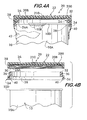
- the holding device 20 basically comprises a cap which is arranged to be secured to the container 10 over its lid or top wall 10B.
- the cap could just as easily be secured over the base or bottom wall 10C.
- the cap basically comprises a disk-like member 22 and an ring-like insert 24, each of which is preferably made of plastic or some other non-metal.
- the member 22 is in the form of a generally planar wall 26 of circular profile having a downwardly depending annular flange 28.
- the inner surface of the flange 28 includes an internal helical thread 30.
- the insert 24 is in the form of a ring having an upper annular portion 32 and a lower annular portion 34
- the upper annular portion 32 has an outside diameter that is approximately equal to the inside diameter of the annular flange 28 and includes an external helical thread 36 for engagement with the internal helical thread 30.
- the engagement of the threads 30 and 36 releasably secures the disk-like member 22 to the ring-like insert 24.
- the lower annular portion 34 depends downward from the upper portion 32 and is of larger outside diameter than the outside diameter of the upper portion 32.
- the inner surface of the lower annular portion 34 includes an annular recess 38 whose inside diameter is just slightly larger than the outside diameter of the upper or lower beads 10D and 10E, respectively, of the can 10.
- the recess 38 is provided to enable the upper or lower bead of the can to be snap-fit therein to mount the assembled cap 22 on the can 10.
- the bottom end of the lower annular portion 34 of the ring-like insert includes a projection or lip having a cam surface 40 extending inward radially. This projection is arranged to flex slightly to enable the bead of the can to slide over the cam surface 40 and into the contiguous recess 38, thereby releasably locking the holding device (cap) 20 in place on the can.
- the undersurface 26A of the holding device 20 When so mounted the undersurface 26A of the holding device 20 will be spaced from the metallic lid of the can 10.
- the undersurface 26A thus can serve as the location for mounting the security tag, e.g., tag 200, to space the tag from the metal of the lid 10B (or the base 10C, if the cap 20 is mounted over the base).
- the security tag e.g., tag 200
- the signal compromising effect of that metal is overcome.
- the spacing of the tag from the metal lid overcomes the signal amplitude attenuating effect of the metal of the lid.
- the amount of spacing between the tag and the metal lid or base can be determined empirically or otherwise to enable the tag when mounted on the can to provide a discernable return signal of a desired amplitude and within a desired frequency range to be readily read by the receiver of the security system.
- the manner of calibrating the tag for such operation will be described later.
- the tag 20 can be held onto the undersurface 26A of the holding device or cap 20 in various manners.
- an adhesive is used. That adhesive may be in the form of a coating 210 on the substrate 208 of the tag 200.
- the holding device (cap) 20 is snap-fit on the container 10, it may be readily removed by the user (purchaser) of the product to provide the user with access to the lid (or base, as the case may be) of the container. In particular, all that is required to provide such access is for the user to pull the cap 20 upward with respect to the can 10, whereupon the bead 10D will exit from the annular recess 38, thereby freeing the cap from the can. The user can then open the can's lid 10B by merely pulling on the pull tab 12.
- a seal or wrap can be provided about the holding device and the container to hold the two together.
- a wrap 42 in the form of a heat shrinkable band, may be provided about the entire holding device/can combination or only about the holding device and a contiguous portion of the can.
- the wrap need not be heat shrinkable.
- Other mechanisms for sealing the cap 20 onto the container are envisioned, such as using an adhesive seal, a paper seal, or using a cap integrally formed on the container. The last option is similar to the way milk containers are sealed.
- a holding device or cap 120 constructed for use with this invention.
- the cap 120 is similar in most respects to the holding device 20, except that it is a unitary structure that is not made up of a disk-like member and ring-like insert.
- the holding device 120 makes use of a spacer, to be described later, that is located between the metal portion of the can 10 and the portion of the holding device 120 at which the security tag 200 is located.
- the common components of the holding devices 20 and 120 will be given the same reference numbers.
- the holding device 120 basically comprises a integral member, preferably formed of plastic or some other suitable non-metal, and having a generally planar wall 126 of circular profile and a downwardly depending annular flange 128.
- the inner surface of the annular flange 128 includes an annular recess 38 whose inside diameter is just slightly larger than the outside diameter of the upper or lower beads 10D and 10E, respectively, of the can 10.
- the recess 38 is provided to enable the upper or lower bead of the can to be snap-fit therein to mount the assembled cap 120 on the can 10.
- the bottom end of the lower annular portion 34 of the ring-like insert includes a projection having a cam surface 40 extending inward radially. This projection is arranged to flex slightly to enable the bead of the can to slide over its outer surface and into the contiguous recess, thereby releasably locking the holding device 120 in place on the can 10.
- the planar wall 126 includes an undersurface 126A, which like the embodiment 20 serves as the location for mounting the security tag 200, whereupon the tag of the holding device will be spaced from the metallic lid of the can 10.
- a physical spacer element 102 is provided in the holding device 120 to sandwich the tag 200 between it and the undersurface 126A of the cap 120.
- the spacer 102 basically comprises a disk-like member formed of plastic or some other suitable non-metal.
- the outside diameter of the spacer is approximately equal to the inside diameter of the annular flange 128, and the thickness of the spacer is such that its lower surface is flush with the upper edge of the annular recess 28 when the tag is sandwiched therebetween, as clearly shown in Fig. 7A .
- the tag 200 can be held in place by an adhesive layer 210 as described earlier. Since the tag will be sandwiched between the spacer 102 and the undersurface 126 of the cap member the adhesive 210 may be omitted.
- the holding device 120 may make use of a wrap 42 to hold it in place on the container to deter its removal from the container.
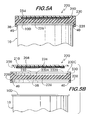
- FIGs. 5A and 5B there is shown another exemplary embodiment of a holding device 220 for use with this invention.
- the holding device 220 is perhaps the most preferred of the various embodiments since it is constructed to have a portion serving as a label for the container 10 to which the device 220 is secured.
- the device 220 includes various features common to the holding devices 20 and 120. In the interest of brevity the common components of those devices will be given the same reference numbers.
- the holding device or cap 220 basically comprises an integral member, preferably formed of plastic or some other suitable non-metal, and having a generally planar central wall 226 of circular profile, a downwardly depending annular flange 228 and an upwardly depending annular flange 230.
- the inner surface of the downwardly depending annular flange 128 includes an annular recess 38 whose inside diameter is just slightly larger than the outside diameter of the upper or lower beads 10D and 10E, respectively, of the can 10.
- the recess 38 is provided to enable the upper or lower bead of the can to be snap-fit therein to mount the assembled cap 220 on the can 10.
- the bottom end of the lower annular portion 34 of the ring-like insert includes a projection having a cam surface 40 extending inward radially. This projection is arranged to flex slightly to enable the bead of the can to slide over its outer surface and into the contiguous recess, thereby releasably locking the holding device 220 in place on the can 10.
- the planar wall 226 includes a stepped circular shaped recess 232 in its top surface.
- the recess 232 includes a lower section 232A and an upper section 232B,
- the inside diameter of the upper section is larger than the inside diameter of the lower section to form an annular ledge 232C.
- This surface serves to receive an annular disk-like member 234, which can be used to form a label for the device/article to be tagged.
- the label 234 basically comprises a sheet of plastic, cardboard, paper or some other material which can bear indicia, e..g, text, graphics, etc., thereon.
- the outside diameter of the label 234 is slightly less than the inside diameter of the recess section 232A so that its peripheral edge can rest on and be secured by means, e.g., an adhesive (not shown) to the top surface of the ledge 232C.
- the undersurface of the label 234 serves as the location on which the tag 200 is mounted. To that end, the tag is secured to the undersurface of the label 234 by the adhesive 210.
- the height of the recess section 232B is selected to be at least equal to the thickness of the label 232.
- the height of the recess section 232A is selected to be at least equal to the combined thickness of the tag 200 and the adhesive layer 210.
- the label fits flush within the cap as shown in Fig. 5A , with the thickness of the planar wall 226 spacing the tag from the metal lid 10B of the container.
- the adhesive securement of the label to the cap device 220 prevents the surreptitious removal of the tag.
- the holding device 220 may make use of a wrap 42 to hold the device in place on the container to deter removal of the device.
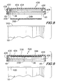
- FIGs. 6A and 6B there is shown another exemplary embodiment of a holding device or cap 320 constructed for use with this invention.
- the holding device 320 is similar in many respects to the holding device 220 in that it makes use of a label to serve as the means for holding the tag in place.
- the holding device 320 basically comprises an integral member, preferably formed of plastic or some other suitable non-metal, and having a generally planar central wall 326 of circular profile, a downwardly depending annular flange 328 and an upwardly depending annular flange 330.
- the inner surface of the downwardly depending annular flange 128 includes an annular recess 38 whose inside diameter is just slightly larger than the outside diameter of the upper or lower beads 10D and 10E, respectively, of the can 10.
- the recess 38 is provided to enable the upper or lower bead of the can to be snap-fit therein to mount the assembled cap 320 on the can 10.
- the bottom end of the lower annular portion 328 includes a projection having a cam surface 40 extending inward radially. This projection is arranged to flex slightly to enable the bead of the can to slide over its outer surface and into the contiguous recess, thereby releasably locking the holding device 220 in place on the can 10.
- the upper annular flange 330 includes a top surface 332 in which an annular recess 334 is located.
- a pair of opposed annular lips 336 extend towards each other on opposite sides of the recess 334 contiguous with the top surface 332.
- the lips 336 are angled slightly downward to create a tapering entryway to the recess 334. This entryway and recess serves as the means for securing a label to the cap device 320, as will be described hereinafter.
- the label basically comprises a disk-like member 338 of circular profile and which can bear indicia, e..g, text, graphics, etc., thereon.
- the undersurface of the label serves as the location for mounting the security tag 200 in the same manner as described earlier, e.g., via the use of the adhesive 210.
- the label is arranged to be secured to the cap device 320 via the recess 334.
- an annular ridge 340 projects downward from the undersurface of the label member 338 closely adjacent the periphery thereof. The ridge in cross-section resembles an arrowhead.
- the label 338 with the tag secured to its bottom surface as described above when placed over the cap device 320 it can be pressed downward to secure it to the cap device.
- the downward push causes the arrowhead portion of the label's ridge 338 to pass through the tapering entryway to the recess 334, thereby causing the lips 336 to flex to enable the arrowhead portion of the ridge to pass therethrough into the recess.
- the lips flex back to lock the arrowhead portion of the ridge within the recess. This action effectively secures the label 338 onto the cap device 320, thereby preventing surreptitious removal of the tag 200.
- the holding device 320 may make use of a wrap 42 to hold the device in place on the container to deter removal of the device.
- FIG. 8 there is shown another exemplary embodiment of a holding device 420 constructed for use with this invention.
- the holding device 420 is similar in many respects to the holding device 120 in that it makes use of a unitary construction, but does not include a spacer element and includes alternative means for securing the tag 200 in place.
- the holding device or cap 420 basically comprises an integral member, preferably formed of plastic or some other suitable non-metal, and having a generally planar central wall 426 of circular profile, a downwardly depending annular flange 428, and an intermediate annular flange 430.
- the intermediate flange extends radially inward from the inner surface of the downwardly depending annular flange 428.
- the inner surface of the downwardly depending annular flange 428 includes an annular recess 38 located immediately below the intermediate flange 430.
- the annular recess 28 has an inside diameter just slightly larger than the outside diameter of the upper or lower beads 10D and 10E, respectively, of the container 10 to enable it to receive either the top or bottom beads of the container to secure the holding device 420 on the container in the same manner as described earlier.
- the tag 200 is arranged to be secured to the undersurface of the generally planar central wall 426 without the use of any adhesive.
- an annular wall or ridge 432 projects downward from the undersurface of the central wall 426.
- An annular recess 434 is located in the ridge 432 to enable the circular tag 200 to be snap-fit therein.
- the bottom end of the annular ridge 432 includes a projection having a cam surface 40 extending inward radially. This projection is arranged to flex slightly to enable the periphery of the circular tag 200 to slide over its cam surface and into the contiguous recess 434, thereby locking the tag 200 in place in that recess under the central wall 426 of the cap 420.
- the tag 200 When the tag is so mounted and the holding device or cap 420 is mounted on the container 10 the tag 200 will be spaced from the metallic lid of the can 10.
- the holding device 420 may make use of a wrap 42 to hold the device in place on the container to deter removal of the device.
- FIG. 9 there is shown another exemplary embodiment of a holding device 520 constructed for use with this invention.
- the holding device 520 is similar in many respects to the holding device 420 except that it makes use of the adhesive securement of the tag to the device.
- the holding device or cap 520 basically comprises an integral member, preferably formed of plastic or some other suitable non-metal, and having a generally planar central wall 426 of circular profile, a downwardly depending annular flange 428, and an intermediate annular flange 430.
- the intermediate flange extends radially inward from the inner surface of the downwardly depending annular flange 428.
- the inner surface of the downwardly depending annular flange 428 includes an annular recess 38 located immediately below the intermediate flange 430.
- the annular recess 28 has an inside diameter just slightly larger than the outside diameter of the upper or lower beads 10D and 10E, respectively, of the container 10 to enable it to receive either the top or bottom beads to secure the holding device 420 on the container in the same manner as described earlier.
- the tag 200 is arranged to be secured to the undersurface of the generally planar central wall 426 of the holding device 520 by use of an adhesive.
- the adhesive is preferably in the form of a coating 210 on the substrate 208 of the tag 200.
- the holding device 520 may make use of a wrap 42 to hold the device in place on the container to deter removal of the holding device.
- a holding device or cap for use with this invention may not include the annular recess for securing it to a container.
- securing mechanisms could be used, such as grooves, adhesives, fasteners, or other devices.
- some embodiments merely space the tag from the metal portion of the container by air, other embodiments make use of a physical spacer element, essentially sandwiching the tag between the top of the cap and the spacer element.
- the spacer like the cap itself, is preferably made of plastic for economic & magnetic purposes as it is readily available and a dielectric. However, other materials may be substituted for plastic, as known in the art.
- Calibration according to this invention of the tag/holding device for use on a particular container is accomplished in the following general manner.
- the following utlines the general method steps for determining the necessary frequency that the tag needs to be designed at so that transceivers can receive the desired signal.
- transceivers of EAS tags listen for a return signal at 8,2 MHz. Though the frequency of the tag will be different for each type of container, most of the tags have a return frequency set to 7,0 MHz.
- the inductance is 0,9 ⁇ H and the capacitance is 521 pF. These ranges are exemplary and other values can be used to achieve the desired frequency. Also, other frequencies can be used such 13,56 MHz.
- tags return frequency All frequencies that are commonly received by receivers are envisioned as possible modifications to the tags return frequency. While other transceivers can easily be designed to receive drastically different frequencies, it is desirable to design this tag to work at this specific frequency so that it will be compatible with existing transceivers. While it is contemplated to have the transceiver emit a signal so that tag returns a signal at 8,2 MHz, or simply have the transceiver listen at a different frequency, it is desirable to enable the tag to be compatible with other tags and security systems.
- the tag used with the current invention returns a signal with a strength of 2,5-6,0 units.
- Higher strengths are envisioned as technological limitations allow.
- the signal strength needs to be greater, because the metallic container has a shielding effect on the return signal.
- the tag's return signal is made stronger so the receiver can receive an intelligible signal from the tag.
- Every canister, jar, can, or container has a different disruptive capacity on the magnet field generated by the tag.
- the container disturbs the frequency the tag resonates at, and reduces the magnitude of the signal.
- the container can be modified by varying the capacitance or inductance of the tag to raise or lower the signal at which the tag resonates.
- the tag is spaced away from the container. While the unique properties of the container will determine how far the tag will need to be spaced, the tag will generally be spaced at least 1 cm from the top of the container. The further away the container is, the greater the signal strength. Combining the two steps yields the distance the tag should be spaced and the limitations of the structure of the tag.
- This new tag is designed so that when it is placed onto a metallic container a standard transceiver for security tags can detect the signal.
- the tag is structured to be able to return a signal when attached to a metallic container means that it is required that the signal is strong enough so that a standard pedestal-style transceiver, the standard distance away (1,2 - 1,8 m or 4-6 feet), can detect the signal.
- a standard pedestal-style transceiver is the Checkpoint Liberty PX pedestal.
- the finished product i.e., the container with the holding device supporting a security tag thereon spaced from the container
- the finished product is made by placing the tag into the cap, placing the spacer under the tag (if the holding device makes use of a spacer element), placing the cap on the container's lid, and optionally placing a safety seal or wrap over the cap and container.
- the cap could place the cap on the bottom of the container and place a standard cap on the top of the device.
- one aspect of the subject invention entails use of a special cap or tag holder that has a spacer inside of it which effectively brings the tag a given distance away from the metal top, lid, or cap of a container to be tagged. This drastically reduces the effect the metal structure of the container has on shielding the resonance signal of the tag. Without the spacer, the container blocks or at least substantially degrades the tag's return signal.
- the above aspects include, e.g., a holding device that optionally has a spacer inside of it to allow a security tag to be spaced far enough away from a metallic portion of a container to provide an intelligible signal to be received by the receiver, a security tag that is powerful enough and is calibrated correctly to send a discernable signal back to the transceiver amidst the distortion and shielding caused by the metallic portion of the container, and a method of designing and calibrating security tags for appropriate operation on containers having at least one metallic portion using the holding devices constructed for use with this invention. It should also be pointed out at this juncture, that while use of the tag shown in Fig. 3 is a preferred way to effectively tag a container having a metallic portion, conventionally constructed and shaped security tags may, in some cases, be used, depending upon the construction of the container/can and the size of the tag.
Landscapes
- Engineering & Computer Science (AREA)
- Physics & Mathematics (AREA)
- General Physics & Mathematics (AREA)
- Electromagnetism (AREA)
- Mechanical Engineering (AREA)
- Automation & Control Theory (AREA)
- Computer Security & Cryptography (AREA)
- Computer Hardware Design (AREA)
- Microelectronics & Electronic Packaging (AREA)
- Theoretical Computer Science (AREA)
- Burglar Alarm Systems (AREA)
- Details Of Rigid Or Semi-Rigid Containers (AREA)
Applications Claiming Priority (3)
| Application Number | Priority Date | Filing Date | Title |
|---|---|---|---|
| US61407204P | 2004-09-29 | 2004-09-29 | |
| US11/119,857 US7583194B2 (en) | 2004-09-29 | 2005-05-02 | Method and system for tracking containers having metallic portions, covers for containers having metallic portions, tags for use with container having metallic portions and methods of calibrating such tags |
| EP05801771A EP1794058A2 (de) | 2004-09-29 | 2005-09-28 | Verfahren und system zum verfolgen von behältern mit metallteilen, deckel für behälter mit metallteilen, etiketten zur verwendung bei behältern mit metallteilen und verfahren zum kalibrieren solcher etiketten |
Related Parent Applications (1)
| Application Number | Title | Priority Date | Filing Date |
|---|---|---|---|
| EP05801771A Division EP1794058A2 (de) | 2004-09-29 | 2005-09-28 | Verfahren und system zum verfolgen von behältern mit metallteilen, deckel für behälter mit metallteilen, etiketten zur verwendung bei behältern mit metallteilen und verfahren zum kalibrieren solcher etiketten |
Publications (1)
| Publication Number | Publication Date |
|---|---|
| EP2045190A1 true EP2045190A1 (de) | 2009-04-08 |
Family
ID=35672449
Family Applications (2)
| Application Number | Title | Priority Date | Filing Date |
|---|---|---|---|
| EP09151369A Withdrawn EP2045190A1 (de) | 2004-09-29 | 2005-09-28 | Sicherheitsvorrichtung zum Verfolgen von Behältern mit metallteilen und Verfahren zur Kennzeichnung von einem Behälter |
| EP05801771A Withdrawn EP1794058A2 (de) | 2004-09-29 | 2005-09-28 | Verfahren und system zum verfolgen von behältern mit metallteilen, deckel für behälter mit metallteilen, etiketten zur verwendung bei behältern mit metallteilen und verfahren zum kalibrieren solcher etiketten |
Family Applications After (1)
| Application Number | Title | Priority Date | Filing Date |
|---|---|---|---|
| EP05801771A Withdrawn EP1794058A2 (de) | 2004-09-29 | 2005-09-28 | Verfahren und system zum verfolgen von behältern mit metallteilen, deckel für behälter mit metallteilen, etiketten zur verwendung bei behältern mit metallteilen und verfahren zum kalibrieren solcher etiketten |
Country Status (8)
| Country | Link |
|---|---|
| US (2) | US7583194B2 (de) |
| EP (2) | EP2045190A1 (de) |
| JP (1) | JP2008515109A (de) |
| KR (1) | KR20070083827A (de) |
| AU (1) | AU2005291987B2 (de) |
| CA (1) | CA2582145A1 (de) |
| TW (1) | TWI282320B (de) |
| WO (1) | WO2006039461A2 (de) |
Families Citing this family (50)
| Publication number | Priority date | Publication date | Assignee | Title |
|---|---|---|---|---|
| WO2006009140A1 (ja) * | 2004-07-20 | 2006-01-26 | Dai Nippon Printing Co., Ltd. | 無線icタグ付き包装体 |
| EP1803086B1 (de) * | 2004-10-22 | 2013-07-24 | Kabushiki Kaisha Sato | Vorrichtung zum aufbringen eines rfid-etikettenträgerlabels auf einem objekt |
| JP4427063B2 (ja) * | 2004-11-16 | 2010-03-03 | 株式会社ハネックス | データキャリア装着体及びその製造方法 |
| GB2438571A (en) * | 2005-04-01 | 2007-11-28 | Inter Basic Resources Inc | Automatic product expiration alert device |
| WO2007000578A2 (en) | 2005-06-25 | 2007-01-04 | Omni-Id Limited | Electromagnetic radiation decoupler |
| JP4569442B2 (ja) * | 2005-10-26 | 2010-10-27 | 株式会社デンソーウェーブ | コンテナボックス |
| US7342501B2 (en) | 2006-02-07 | 2008-03-11 | Owens-Illinois Healthcare Packaging Inc. | Closure and package with induction seal and RFID tag |
| US8807438B2 (en) * | 2006-02-22 | 2014-08-19 | Toyo Seikan Kaisha, Ltd. | RFID tag substrate for metal component |
| GB0611983D0 (en) | 2006-06-16 | 2006-07-26 | Qinetiq Ltd | Electromagnetic radiation decoupler |
| JP4840917B2 (ja) * | 2006-07-12 | 2011-12-21 | 日本クラウンコルク株式会社 | Icタグ付蓋体 |
| JP4840918B2 (ja) * | 2006-07-12 | 2011-12-21 | 日本クラウンコルク株式会社 | Icタグ付蓋体 |
| US8547230B1 (en) * | 2006-07-17 | 2013-10-01 | Lockheed Martin Corporation | Unobtrusive proprioceptive monitor for shipping containers and vehicles |
| US7583195B2 (en) * | 2006-08-22 | 2009-09-01 | Checkpoint Systems, Inc. | Security tag adapter for containers |
| JP4820726B2 (ja) * | 2006-09-27 | 2011-11-24 | 株式会社日立情報システムズ | 金属製加圧容器用rfidタグシステム |
| US7760099B2 (en) * | 2006-11-03 | 2010-07-20 | Codan Us Corporation | Radio frequency verification system and device |
| US7586417B2 (en) * | 2006-11-10 | 2009-09-08 | Rexam Healthcare Packaging Inc. | RFID insert with disable feature and container that includes such an insert |
| US7875227B2 (en) * | 2006-12-01 | 2011-01-25 | Rexam Healthcare Packaging Inc. | Molded plastic container and preform having insert-molded RFID tag |
| US7850893B2 (en) | 2006-12-01 | 2010-12-14 | Rexam Healthcare Packaging Inc. | Molded plastic container and preform having insert-molded RFID tag |
| GB0624915D0 (en) * | 2006-12-14 | 2007-01-24 | Qinetiq Ltd | Switchable radiation decoupling |
| GB0625342D0 (en) * | 2006-12-20 | 2007-01-24 | Qinetiq Ltd | Radiation decoupling |
| US7609166B2 (en) * | 2007-01-04 | 2009-10-27 | Avery Dennison Corporation | RFID tag housing |
| US8421632B2 (en) * | 2007-03-22 | 2013-04-16 | Toyo Seikan Kaisha, Ltd. | Plastic cap with IC tag and method of attaching IC tag to the cap |
| JP5105931B2 (ja) * | 2007-03-29 | 2012-12-26 | 東洋製罐株式会社 | Icタグ付プラスチックキャップ |
| US20080314900A1 (en) * | 2007-06-14 | 2008-12-25 | Drug Plastics & Glass Company, Inc. | Enclosure having an automatic identification device |
| US20080308518A1 (en) * | 2007-06-14 | 2008-12-18 | Drug Plastics & Glass Company, Inc. | Container having an automatic identification device for identifying the contents therein |
| US8120484B2 (en) | 2007-06-14 | 2012-02-21 | Rexam Healthcare Packaging Inc. | Closure and package with RFID kernel tag and boost antenna |
| US8800860B2 (en) * | 2007-12-04 | 2014-08-12 | E. Van Zanten Holding B.V. | Plurality of plant pots for use in cultivating plants, assembly comprising such a plurality of plant pots, as well as a method for cultivating plants |
| US9174791B2 (en) | 2007-12-11 | 2015-11-03 | Tokitae Llc | Temperature-stabilized storage systems |
| US8485387B2 (en) * | 2008-05-13 | 2013-07-16 | Tokitae Llc | Storage container including multi-layer insulation composite material having bandgap material |
| US7999672B1 (en) * | 2008-04-22 | 2011-08-16 | Display Technologies, Inc. | Anti-theft box and method of making same |
| US20090266736A1 (en) * | 2008-04-25 | 2009-10-29 | Drug Plastics & Glass Company, Inc. | Container having an identification device molded therein and method of making same |
| WO2009154292A1 (ja) * | 2008-06-20 | 2009-12-23 | 東洋製罐株式会社 | Icタグ付樹脂製オーバーキャップ |
| US20100102968A1 (en) * | 2008-06-23 | 2010-04-29 | Tag (Bvi) Ltd. | Electronic article surveillance device and related assembly and method |
| US8794533B2 (en) * | 2008-08-20 | 2014-08-05 | Omni-Id Cayman Limited | One and two-part printable EM tags |
| KR100899901B1 (ko) * | 2008-10-27 | 2009-05-29 | 대한민국 | 무선인식태그가 내장된 용기 뚜껑 |
| FR2953620B1 (fr) * | 2009-12-07 | 2013-11-22 | Areva Nc | Dispositif d'identification d'un support metallique present dans un environnement poussiereux et metallique, a encombrement reduit et application a l'identification de conteneur contenant des elements de combustible nucleaire dans leur usine de fabrication |
| US9372016B2 (en) | 2013-05-31 | 2016-06-21 | Tokitae Llc | Temperature-stabilized storage systems with regulated cooling |
| US9447995B2 (en) | 2010-02-08 | 2016-09-20 | Tokitac LLC | Temperature-stabilized storage systems with integral regulated cooling |
| US8963720B2 (en) * | 2010-05-11 | 2015-02-24 | The Boeing Company | RFID tag container |
| US8851389B2 (en) * | 2011-08-08 | 2014-10-07 | William Frick & Company | RFID aerospace industry tag and method of use |
| GB2493996B (en) * | 2011-11-18 | 2013-12-04 | David Bernard Mapleston | Long Range UHF RFID Tag for bottles |
| US9227019B2 (en) * | 2012-08-29 | 2016-01-05 | Amgen Inc. | Pre-filled syringe identification tag |
| US9505529B2 (en) * | 2014-01-14 | 2016-11-29 | B&G Plastics, Inc. | Overcap for supporting an electronic tag to a bottle cap |
| US9605448B2 (en) | 2015-07-07 | 2017-03-28 | Se-Kure Controls, Inc. | Security system for candles |
| RU2754986C1 (ru) * | 2017-10-16 | 2021-09-08 | Гкл Энтернасьональ Сарл | Закрывающий элемент |
| IT201800004619A1 (it) * | 2018-04-17 | 2019-10-17 | Contenitore di un prodotto cosmetico o medicale | |
| SE542229C2 (en) * | 2018-07-02 | 2020-03-17 | Stora Enso Oyj | A metal container comprising a uhf rfid tag |
| US20200051463A1 (en) * | 2018-08-10 | 2020-02-13 | Avery Dennison Retail Information Services, Llc | Intelligent advertising insert method, system, and apparatus |
| JP7251305B2 (ja) * | 2019-05-16 | 2023-04-04 | 凸版印刷株式会社 | Icタグラベルおよび開封検知機能付イージーピール容器 |
| US20210147118A1 (en) * | 2019-11-20 | 2021-05-20 | ARK Operations, Inc. | Systems and methods for tracking chain of custody of a container and its contents |
Citations (4)
| Publication number | Priority date | Publication date | Assignee | Title |
|---|---|---|---|---|
| US5081445A (en) | 1991-03-22 | 1992-01-14 | Checkpoint Systems, Inc. | Method for tagging articles used in conjunction with an electronic article surveillance system, and tags or labels useful in connection therewith |
| EP1083519A2 (de) | 1999-09-09 | 2001-03-14 | Supersensor (Proprietary) Limited | Verfahren zur Befestigungen HF transpondern auf Kontainern |
| US20030089513A1 (en) | 2000-05-05 | 2003-05-15 | Checkpoint Systems International Gmbh | Radio frequency (RF) security element, coil and capacitor for an RF-security element and method for production thereof |
| US20040050724A1 (en) * | 2000-07-13 | 2004-03-18 | Grul Derek John | Promotional system |
Family Cites Families (21)
| Publication number | Priority date | Publication date | Assignee | Title |
|---|---|---|---|---|
| US3369538A (en) * | 1966-03-21 | 1968-02-20 | Frey | Canned food container |
| US4721217A (en) * | 1986-08-07 | 1988-01-26 | Optical Coating Laboratory, Inc. | Tamper evident optically variable device and article utilizing the same |
| US4813564A (en) * | 1988-02-25 | 1989-03-21 | Westinghouse Electric Corp. | Package |
| US5139163A (en) * | 1991-11-29 | 1992-08-18 | Diaz Eusebio M | Hygienic seal and cover for food and drink containers |
| FR2740109B1 (fr) | 1995-10-20 | 1997-12-05 | Sensormatic France Sa | Couvercle ou manchon, pour bouteille ou recipient, muni d'un marqueur integre pour la surveillance electronique, et leurs procedes de fabrication |
| JPH09292837A (ja) * | 1996-04-25 | 1997-11-11 | Kobayashi Kk | 共震タグ付き食器及び共振タグブロック |
| US5996832A (en) * | 1996-06-26 | 1999-12-07 | Henbase 3172 (Proprietary) Limited | Cover for beverage can |
| US6329915B1 (en) * | 1997-12-31 | 2001-12-11 | Intermec Ip Corp | RF Tag having high dielectric constant material |
| JP4340929B2 (ja) * | 1998-10-02 | 2009-10-07 | ソニー株式会社 | メモリicタグ装置 |
| US6137413A (en) | 1998-10-29 | 2000-10-24 | Sensormatic Electronics Corporation | Cap with integrated eas marker |
| US6271753B1 (en) * | 2000-03-21 | 2001-08-07 | Kavita M Shukla | Smart lid |
| CN1251131C (zh) * | 2000-07-19 | 2006-04-12 | 株式会社哈尼克斯 | 射频识别标签的收容结构,安装结构及使用该标签的通信 |
| US6342838B1 (en) | 2000-08-29 | 2002-01-29 | B&G Plastics, Inc. | Electronic article surveillance marker and container therewith |
| US6486783B1 (en) * | 2000-09-19 | 2002-11-26 | Moore North America, Inc. | RFID composite for mounting on or adjacent metal objects |
| US20030235027A1 (en) | 2002-01-09 | 2003-12-25 | Larry Smeyak | Method of making interactive information closure and package |
| US6696955B2 (en) | 2002-03-05 | 2004-02-24 | B&G Plastics, Inc. | Electronic article surveillance marker and container therewith |
| US7336243B2 (en) * | 2003-05-29 | 2008-02-26 | Sky Cross, Inc. | Radio frequency identification tag |
| US7126479B2 (en) * | 2004-08-17 | 2006-10-24 | Francis M. Claessens | Metal container closure having integral RFID tag |
| US7049966B2 (en) * | 2003-10-30 | 2006-05-23 | Battelle Memorial Institute Kl-53 | Flat antenna architecture for use in radio frequency monitoring systems |
| JP2005170389A (ja) * | 2003-12-08 | 2005-06-30 | Mitsubishi Materials Corp | Rfidタグ付き金属製容器 |
| US7158033B2 (en) * | 2004-09-01 | 2007-01-02 | Avery Dennison Corporation | RFID device with combined reactive coupler |
-
2005
- 2005-05-02 US US11/119,857 patent/US7583194B2/en not_active Expired - Fee Related
- 2005-09-28 EP EP09151369A patent/EP2045190A1/de not_active Withdrawn
- 2005-09-28 AU AU2005291987A patent/AU2005291987B2/en not_active Ceased
- 2005-09-28 JP JP2007534788A patent/JP2008515109A/ja not_active Ceased
- 2005-09-28 EP EP05801771A patent/EP1794058A2/de not_active Withdrawn
- 2005-09-28 KR KR1020077009571A patent/KR20070083827A/ko not_active Ceased
- 2005-09-28 CA CA002582145A patent/CA2582145A1/en not_active Abandoned
- 2005-09-28 TW TW094133741A patent/TWI282320B/zh not_active IP Right Cessation
- 2005-09-28 WO PCT/US2005/035140 patent/WO2006039461A2/en not_active Ceased
-
2009
- 2009-07-31 US US12/533,421 patent/US20090289769A1/en not_active Abandoned
Patent Citations (4)
| Publication number | Priority date | Publication date | Assignee | Title |
|---|---|---|---|---|
| US5081445A (en) | 1991-03-22 | 1992-01-14 | Checkpoint Systems, Inc. | Method for tagging articles used in conjunction with an electronic article surveillance system, and tags or labels useful in connection therewith |
| EP1083519A2 (de) | 1999-09-09 | 2001-03-14 | Supersensor (Proprietary) Limited | Verfahren zur Befestigungen HF transpondern auf Kontainern |
| US20030089513A1 (en) | 2000-05-05 | 2003-05-15 | Checkpoint Systems International Gmbh | Radio frequency (RF) security element, coil and capacitor for an RF-security element and method for production thereof |
| US20040050724A1 (en) * | 2000-07-13 | 2004-03-18 | Grul Derek John | Promotional system |
Also Published As
| Publication number | Publication date |
|---|---|
| WO2006039461A2 (en) | 2006-04-13 |
| KR20070083827A (ko) | 2007-08-24 |
| WO2006039461A3 (en) | 2006-07-06 |
| AU2005291987B2 (en) | 2009-10-08 |
| EP1794058A2 (de) | 2007-06-13 |
| JP2008515109A (ja) | 2008-05-08 |
| TWI282320B (en) | 2007-06-11 |
| US7583194B2 (en) | 2009-09-01 |
| TW200616846A (en) | 2006-06-01 |
| US20060086808A1 (en) | 2006-04-27 |
| US20090289769A1 (en) | 2009-11-26 |
| CA2582145A1 (en) | 2006-04-13 |
| AU2005291987A1 (en) | 2006-04-13 |
Similar Documents
| Publication | Publication Date | Title |
|---|---|---|
| AU2005291987B2 (en) | Method and system for tracking containers having metallic portions, covers for containers having metallic portions, tags for use with container having metallic portions and methods of calibrating such tags | |
| EP1675216B1 (de) | Verfahren zum Anbringen drahtloser Kommunikationsbauteile | |
| US6137413A (en) | Cap with integrated eas marker | |
| US7528727B2 (en) | Tracking device for polymeric packaging | |
| US7724139B2 (en) | Universal tracking assembly | |
| US20080174437A1 (en) | Universal tracking assembly | |
| US8081078B2 (en) | Universal tracking assembly | |
| US20090201155A1 (en) | Universal tracking assembly | |
| EP3642815B1 (de) | Detektierbare gefaltete spule | |
| US11544518B2 (en) | Deactivatable metal tag | |
| MX2007003768A (es) | Metodo y sistemas para rastrear contenedores que tienen porciones metalicas, cubiertas para contenedores que tienen porciones metalicas, etiquetas para uso son contenedores que tienen prociones metalicas y metodos para calibrar tales. | |
| CN101068722A (zh) | 追踪具有金属部分的容器和容器盖的方法和系统、与具有金属部分的容器一起使用的标签及标定这种标签的方法 | |
| EP1808835B1 (de) | Schöpfvorrichtung für einen Behälter mit elektromagnetischer Überwachungsvorrichtung | |
| US20260015148A1 (en) | Rfid inlay assembly and closure containing same | |
| CA2710927A1 (en) | Method of shipping and tracking inventory | |
| KR200197266Y1 (ko) | 도난방지용 감지수단이 구비된 기록매체 |
Legal Events
| Date | Code | Title | Description |
|---|---|---|---|
| PUAI | Public reference made under article 153(3) epc to a published international application that has entered the european phase |
Free format text: ORIGINAL CODE: 0009012 |
|
| 17P | Request for examination filed |
Effective date: 20090126 |
|
| AC | Divisional application: reference to earlier application |
Ref document number: 1794058 Country of ref document: EP Kind code of ref document: P |
|
| AK | Designated contracting states |
Kind code of ref document: A1 Designated state(s): AT BE BG CH CY CZ DE DK EE ES FI FR GB GR HU IE IS IT LI LT LU LV MC NL PL PT RO SE SI SK TR |
|
| RIN1 | Information on inventor provided before grant (corrected) |
Inventor name: APPALUCCI, LAWRENCE Inventor name: MCGOLDRICK, DAVE Inventor name: WEST, GEORGE Inventor name: ROBERTS, PAUL |
|
| 17Q | First examination report despatched |
Effective date: 20090619 |
|
| AKX | Designation fees paid |
Designated state(s): AT BE BG CH CY CZ DE DK EE ES FI FR GB GR HU IE IS IT LI LT LU LV MC NL PL PT RO SE SI SK TR |
|
| R17C | First examination report despatched (corrected) |
Effective date: 20091216 |
|
| STAA | Information on the status of an ep patent application or granted ep patent |
Free format text: STATUS: THE APPLICATION IS DEEMED TO BE WITHDRAWN |
|
| 18D | Application deemed to be withdrawn |
Effective date: 20100427 |