EP2045399A2 - Baumaschine mit Werkzeugkastenöffnung zur Vorderseite der Maschine - Google Patents
Baumaschine mit Werkzeugkastenöffnung zur Vorderseite der Maschine Download PDFInfo
- Publication number
- EP2045399A2 EP2045399A2 EP08016936A EP08016936A EP2045399A2 EP 2045399 A2 EP2045399 A2 EP 2045399A2 EP 08016936 A EP08016936 A EP 08016936A EP 08016936 A EP08016936 A EP 08016936A EP 2045399 A2 EP2045399 A2 EP 2045399A2
- Authority
- EP
- European Patent Office
- Prior art keywords
- tool box
- box door
- upper frame
- equipment
- heavy equipment
- Prior art date
- Legal status (The legal status is an assumption and is not a legal conclusion. Google has not performed a legal analysis and makes no representation as to the accuracy of the status listed.)
- Granted
Links
Images


Classifications
-
- E—FIXED CONSTRUCTIONS
- E02—HYDRAULIC ENGINEERING; FOUNDATIONS; SOIL SHIFTING
- E02F—DREDGING; SOIL-SHIFTING
- E02F9/00—Component parts of dredgers or soil-shifting machines, not restricted to one of the kinds covered by groups E02F3/00 - E02F7/00
- E02F9/08—Superstructures; Supports for superstructures
- E02F9/0858—Arrangement of component parts installed on superstructures not otherwise provided for, e.g. electric components, fenders, air-conditioning units
- E02F9/0891—Lids or bonnets or doors or details thereof
-
- E—FIXED CONSTRUCTIONS
- E02—HYDRAULIC ENGINEERING; FOUNDATIONS; SOIL SHIFTING
- E02F—DREDGING; SOIL-SHIFTING
- E02F9/00—Component parts of dredgers or soil-shifting machines, not restricted to one of the kinds covered by groups E02F3/00 - E02F7/00
- E02F9/08—Superstructures; Supports for superstructures
-
- E—FIXED CONSTRUCTIONS
- E02—HYDRAULIC ENGINEERING; FOUNDATIONS; SOIL SHIFTING
- E02F—DREDGING; SOIL-SHIFTING
- E02F9/00—Component parts of dredgers or soil-shifting machines, not restricted to one of the kinds covered by groups E02F3/00 - E02F7/00
-
- E—FIXED CONSTRUCTIONS
- E02—HYDRAULIC ENGINEERING; FOUNDATIONS; SOIL SHIFTING
- E02F—DREDGING; SOIL-SHIFTING
- E02F9/00—Component parts of dredgers or soil-shifting machines, not restricted to one of the kinds covered by groups E02F3/00 - E02F7/00
- E02F9/08—Superstructures; Supports for superstructures
- E02F9/0833—Improving access, e.g. for maintenance, steps for improving driver's access, handrails
Definitions
- the present invention relates to heavy equipment having a tool box opening in forward direction of the equipment, in which a toll box door mounted on an upper frame can be easily opened and closed, and an auxiliary structure, such as a handrail that is used when an operator ascent toward an engine room, is not required to reduce the manufacturing cost.
- the present invention relates to heavy equipment having a tool box opening in forward direction of the equipment, in which a tool box door can be simply opened and closed through pressing of a button, and the shape of the tool box door can be freely designed to sufficiently secure storage space.
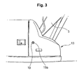
- a caterpillar excavator includes a lower driving structure 1; an upper frame 2 mounted on the lower driving structure 1 to be swiveled; a cap 3 and an engine room 4 mounted in front and in the rear of the upper frame 2; working devices 11 including a boom 5 fixed to the upper frame 2, an arm 6, a bucket 7, and hydraulic cylinders 8, 9, and 10 for driving the boom, the arm, and the bucket, respectively; and a counter weight 12 mounted in the rear of the upper frame 2 to keep the balance of the equipment during working.
- a tool box door 13 is mounted on the upper frame 2 to open from the front to the rear side of the equipment, and a hand rail 16 and an anti-slip plate 17 are installed so that an operator can safely ascend and descend by stepping on the tool box door 13.
- unexplained reference numeral "14" denotes a catch for detachably fixing the tool box door 13 to a tool box body 15 so as to prevent the movement and vibration of the tool box door 13 during traveling or working of the equipment.
- the tool box door 13 is used as a movement path, and thus an upper surface of the tool box door 13, on which an operator steps, is kept as a plane while a section of the tool box is in the form of steps. Accordingly, the tool box door 13 is mounted on the upper frame 2 with limited size and shape.
- the tool box door 13 opens from the front to the rear of the equipment (i.e. it opens from the bottom to the upside of the equipment), the tool box door 13 is restricted by structure when it is mounted on the upper frame 2.
- the tool box door 13 may be simply opened at any time, contrary to the operator's intention, and this may cause the damage of the tool box door.
- an object of the present invention is to provide heavy equipment having a tool box opening in forward direction of the equipment, in which a tool box door mounted on an upper frame can be opened and closed using a button and a gas spring, and the shape of the tool box door can be freely designed to sufficiently secure storage space, so that convenience can be provided to a user.
- Another object of the present invention is to provide heavy equipment having a tool box opening in forward direction of the equipment, in which an operator can ascend toward an engine room without stepping on a tool box door to prevent the damage and deformation of the tool box door, and an auxiliary structure, such as a handrail, an anti-slip plate, and the like, is unnecessary to reduce the manufacturing cost.
- heavy equipment having a tool box opening in forward direction of the equipment, according to an embodiment of the present invention, which includes a lower driving structure; an upper frame mounted on the lower driving structure to be swiveled; a cap and an engine room mounted in front and in the rear of the upper frame; working devices including a boom fixed to the upper frame, an arm, a bucket, and hydraulic cylinders for driving the boom, the arm, and the bucket, respectively; a counter weight mounted in the rear of the upper frame to keep the balance of the equipment during working; a tool box door mounted on the upper frame to open from the rear to the front side of the equipment, and forming storage space; and a gas spring for opening the tool box door when a button mounted on an external surface of the tool box door is pressed.
- the equipment according to an embodiment of the present invention may further include a damping elastic member for preventing an abrupt opening of the tool box door when the tool box door is opened by the gas spring.
- the equipment according to an embodiment of the present invention may further include a protection member mounted on the upper frame to prevent the gas spring and the damping elastic member from being damaged by an external impact.
- the equipment according to an embodiment of the present invention may further include a foothold for ascending and descending formed on the upper frame so that an operator can ascend to the engine room through stepping on the foothold when the tool box door is opened.
- the equipment according to an embodiment of the present invention may further include a handle for ascending and descending formed on one side of the foothold.
- the equipment according to an embodiment of the present invention may further include an embossing part formed to project from an upper surface of the foothold to prevent slipping during ascending or descending.
- Through holes may be formed on the embossing part.
- heavy equipment having a tool box opening in forward direction of the equipment includes a lower driving structure 1; an upper frame 2 mounted on the lower driving structure 1 to be swiveled; a cap 3 and an engine room 4 mounted in front and in the rear of the upper frame 2; working devices 11 including a boom 5 fixed to the upper frame 2, an arm 6, a bucket 7, and hydraulic cylinders 8, 9, and 10 for driving the boom, the arm, and the bucket, respectively; a counter weight 12 mounted in the rear of the upper frame 2 to keep the balance of the equipment during working; a tool box door 13 mounted on the upper frame 2 to open from the rear to the front side of the equipment, and forming storage space 18; and a gas spring 20 for opening the tool box door 13 when a button 19 mounted on an external surface of the tool box door 13 is pressed.
- the equipment according to an embodiment of the present invention further includes a damping elastic member 21 (e.g. a tension spring) for preventing an abrupt opening of the tool box door 13 when the tool box door 13 is opened by the gas spring 20.
- a damping elastic member 21 e.g. a tension spring
- the equipment according to an embodiment of the present invention further includes a protection member and an auxiliary handle 22 mounted on the upper frame 2 to prevent the gas spring 20 and the damping elastic member 21 from being damaged by an external impact.
- the equipment according to an embodiment of the present invention further includes a foothold 23 for ascending and descending formed on the upper frame 2 so that an operator can ascend to the engine room 4 through stepping on the foothold 23 when the tool box door 13 is opened.
- the equipment according to an embodiment of the present invention further includes an embossing part 24 formed to project from an upper surface of the foothold 23 to prevent slipping during ascending or descending.
- Through holes 25 are formed on the embossing part 24.
- the equipment according to an embodiment of the present invention further includes a handle 26 for ascending and descending formed on one side of the foothold 23 (or fixed to a side surface of a hydraulic fluid tank).
- the gas spring 20 is extended during the pressing of the button 19 installed on the outer surface of the tool box door 13, and thus the tool box door 13 is rotated (clockwise) around a hinge part (e.g. a hinge) fixed to the upper frame 2, and thus the tool box door 13 is opened from the rear to the front side of the equipment.
- a hinge part e.g. a hinge
- the tool box door 13 which is opened by the gas spring 20, is prevented from being abruptly opened by a tension force of the elastic member (e.g. tension spring) 21.
- the elastic member e.g. tension spring
- the operator can ascend to an upper part of the engine room 4 by stepping on the lower driving structure 1 and the foothold 23 installed on the upper frame 2 in order.
- the operator can hold on to the handle 26 installed on one side of the foothold 23, the protection member, and the auxiliary handle 22 to keep safely in ascending.
- the operator In the case of ascending the engine room 4 in the winter season or in the rainy season, the operator is prevented from slipping on the foothold 23 by the embossing part 24 projected from the upper surface of the foothold 23 and the through holes 25 formed in the center of the embossing part 24.
- the foothold 23 and the handle 26 for ascending and descending are accommodated and concealed in the storage space 18 of the tool box door 13. Accordingly, it is restricted for the operator to ascend to the upper part of the engine room 4 by stepping on the tool box contrary to the operator's intention.
- the " ⁇ " -shaped protection member and the auxiliary handle 22 are installed on the outside of the elastic member 21 and the gas spring 20, the elastic member 21 and the gas spring 20 are prevented from being damaged by an external impact. Also, in the case of ascending toward the engine room 4 by stepping on the lower driving structure 1, the operator can hold on to the protection member and the auxiliary handle 22 to keep safety in ascending.
- the tool box door 13 Since it is possible for the operator to ascend to the upper part of the engine room 4 without stepping on the tool box door 13 (i.e. the tool box door 13 does not serve as a foothold), the tool box door 13 can be prevented from being damaged or deformed.
- the size and shape of the tool box door 13 mounted on the upper frame 2 can be freely changed, and thus the external appearance of the whole equipment can be improved.
- the tool box door 13 can be locked. Accordingly, even in the case of pressing the button 19, the gas spring 20 is prevented from being extended, and thus the tool box door 13 cannot be opened.
- the heavy equipment having a tool box opening in forward direction of the equipment has the following advantages.
- the tool box door mounted on the upper frame can be opened and closed by the button and the gas spring, and the shape of the tool box door can be freely designed to sufficiently secure storage space, so that convenience can be provided to a user.
- the operator can ascend toward the engine room without directly stepping on the tool box door to prevent the damage and deformation of the tool box door and to lengthen the life span of the tool box door, and an auxiliary structure for safety, such as a handrail, an anti-slip plate, and the like, is unnecessary to reduce the manufacturing cost.
Landscapes
- Engineering & Computer Science (AREA)
- Mining & Mineral Resources (AREA)
- Civil Engineering (AREA)
- General Engineering & Computer Science (AREA)
- Structural Engineering (AREA)
- Component Parts Of Construction Machinery (AREA)
- Fittings On The Vehicle Exterior For Carrying Loads, And Devices For Holding Or Mounting Articles (AREA)
- Superstructure Of Vehicle (AREA)
Applications Claiming Priority (1)
| Application Number | Priority Date | Filing Date | Title |
|---|---|---|---|
| KR1020070099269A KR100945190B1 (ko) | 2007-10-02 | 2007-10-02 | 장비의 앞쪽 방향으로 개방되는 툴박스를 갖는 중장비 |
Publications (3)
| Publication Number | Publication Date |
|---|---|
| EP2045399A2 true EP2045399A2 (de) | 2009-04-08 |
| EP2045399A3 EP2045399A3 (de) | 2017-03-01 |
| EP2045399B1 EP2045399B1 (de) | 2023-07-26 |
Family
ID=40262038
Family Applications (1)
| Application Number | Title | Priority Date | Filing Date |
|---|---|---|---|
| EP08016936.0A Ceased EP2045399B1 (de) | 2007-10-02 | 2008-09-26 | Baumaschine mit Werkzeugkastenöffnung zur Vorderseite der Maschine |
Country Status (5)
| Country | Link |
|---|---|
| US (1) | US7780213B2 (de) |
| EP (1) | EP2045399B1 (de) |
| JP (1) | JP5192959B2 (de) |
| KR (1) | KR100945190B1 (de) |
| CN (1) | CN101403219B (de) |
Cited By (2)
| Publication number | Priority date | Publication date | Assignee | Title |
|---|---|---|---|---|
| EP2474672A4 (de) * | 2009-09-02 | 2017-01-18 | Hitachi Construction Machinery Co., Ltd. | Nutzfahrzeug mit rädern |
| WO2019038347A1 (en) * | 2017-08-24 | 2019-02-28 | Caterpillar Sarl | EXCAVATOR |
Families Citing this family (21)
| Publication number | Priority date | Publication date | Assignee | Title |
|---|---|---|---|---|
| JP5152027B2 (ja) * | 2009-02-13 | 2013-02-27 | コベルコ建機株式会社 | ツールボックス構造 |
| JP5178923B2 (ja) * | 2010-01-26 | 2013-04-10 | 株式会社小松製作所 | 建設機械のエンジンフード |
| KR101037948B1 (ko) * | 2010-08-13 | 2011-05-30 | 김석곤 | 차량용 크레인 운전석 케빈 |
| JP5600050B2 (ja) * | 2010-11-29 | 2014-10-01 | 日立建機株式会社 | 建設機械のサイドカメラ取付構造 |
| CN104169502B (zh) * | 2012-03-16 | 2016-08-10 | 日立建机株式会社 | 工程机械 |
| RU2601634C1 (ru) * | 2012-11-05 | 2016-11-10 | Дир Энд Компани | Интегрированная система управления дверцей и способ ее управления |
| CN103534416B (zh) * | 2012-11-13 | 2015-05-13 | 株式会社小松制作所 | 液压挖掘机 |
| WO2014076760A1 (ja) * | 2012-11-13 | 2014-05-22 | 株式会社小松製作所 | 油圧ショベル |
| US9016419B2 (en) * | 2012-11-13 | 2015-04-28 | Komatsu Ltd. | Hydraulic excavator |
| JP5949793B2 (ja) * | 2014-01-17 | 2016-07-13 | コベルコ建機株式会社 | 建設機械 |
| US9404238B1 (en) * | 2015-01-10 | 2016-08-02 | Bauer Maschinen Gmbh | Construction machine |
| JP6339948B2 (ja) * | 2015-02-18 | 2018-06-06 | 住友建機株式会社 | ショベル |
| US9677249B2 (en) * | 2015-02-19 | 2017-06-13 | Komatsu Ltd. | Work vehicle with stowable user support member |
| JP6495082B2 (ja) * | 2015-04-17 | 2019-04-03 | 日立建機株式会社 | 建設機械 |
| WO2018122951A1 (ja) * | 2016-12-27 | 2018-07-05 | 株式会社小松製作所 | 作業車両 |
| CN106968286A (zh) * | 2017-03-29 | 2017-07-21 | 湖南高福星智能科技有限公司 | 一种具有高效攀爬功能的挖掘工程机械 |
| DE202017104124U1 (de) | 2017-07-11 | 2017-10-13 | Rheinmetall Landsysteme Gmbh | Staukasten für ein gepanzertes Fahrzeug |
| KR20190002885U (ko) | 2018-05-14 | 2019-11-22 | 주식회사구보 | 중장비용 툴박스 조립체 |
| CN110656673A (zh) * | 2019-11-12 | 2020-01-07 | 徐州菲诺特德机械设备有限公司 | 一种挖掘机工具箱安装机构 |
| US11525240B2 (en) * | 2020-07-23 | 2022-12-13 | Caterpillar Underground Mining Pty. Ltd. | Storage assembly for battery energizing switches of electric machines |
| JP7622921B2 (ja) * | 2021-03-31 | 2025-01-28 | 住友建機株式会社 | ショベル |
Family Cites Families (22)
| Publication number | Priority date | Publication date | Assignee | Title |
|---|---|---|---|---|
| JP2895284B2 (ja) * | 1991-10-31 | 1999-05-24 | ヤンマーディーゼル株式会社 | 旋回作業車 |
| JP2591064Y2 (ja) * | 1993-03-30 | 1999-02-24 | 油谷重工株式会社 | 建設機械のタンク装置 |
| US5439150A (en) * | 1993-10-21 | 1995-08-08 | Trahms; Kurt R. | Rear window accessible pick up truck storage box |
| JP3107984B2 (ja) * | 1994-11-14 | 2000-11-13 | 日立建機株式会社 | 建設機械 |
| JP3288912B2 (ja) * | 1995-12-22 | 2002-06-04 | 日立建機株式会社 | 建設機械用収納ボックス |
| JPH10266264A (ja) * | 1997-03-24 | 1998-10-06 | Shin Caterpillar Mitsubishi Ltd | 建設機械における収納ボックス |
| JPH1193215A (ja) * | 1997-09-18 | 1999-04-06 | Yutani Heavy Ind Ltd | 建設機械のステップ構造 |
| JP4032106B2 (ja) * | 1998-08-31 | 2008-01-16 | ヤンマー株式会社 | 超小旋回作業機 |
| CA2261907A1 (en) * | 1999-02-05 | 2000-08-05 | Joseph Brady | Truck storage box |
| JP3673683B2 (ja) * | 1999-09-24 | 2005-07-20 | 株式会社クボタ | 旋回作業機 |
| JP2002266377A (ja) * | 2001-03-09 | 2002-09-18 | Komatsu Ltd | 建設機械における燃料供給装置 |
| JP2004052360A (ja) * | 2002-07-19 | 2004-02-19 | Sumitomo (Shi) Construction Machinery Manufacturing Co Ltd | 油圧ショベルの工具箱取付構造 |
| JP2004116102A (ja) * | 2002-09-25 | 2004-04-15 | Komatsu Ltd | 油圧ショベルの工具収納装置 |
| JP3809954B2 (ja) * | 2002-10-23 | 2006-08-16 | 株式会社小松製作所 | チルトフロアを備えた作業車両 |
| US6929303B1 (en) * | 2002-11-21 | 2005-08-16 | Thomas M. Sharples | Truck bed storage apparatus and tonneau cover |
| JP2004190276A (ja) * | 2002-12-10 | 2004-07-08 | Shin Caterpillar Mitsubishi Ltd | 建設機械における手摺り |
| JP2005112146A (ja) * | 2003-10-07 | 2005-04-28 | Ishikawajima Constr Mach Co | 作業機の燃料タンクの開閉カバー |
| KR100541568B1 (ko) * | 2003-11-13 | 2006-01-11 | 호봉식 | 크레인용 작업의자 안전덮개 |
| JP2006001597A (ja) * | 2004-06-17 | 2006-01-05 | Sumitomo (Shi) Construction Machinery Manufacturing Co Ltd | 収納箱 |
| US7237636B2 (en) * | 2004-07-01 | 2007-07-03 | Cnh America Llc | Vehicle drive access and storage device |
| US20070158154A1 (en) * | 2006-01-12 | 2007-07-12 | Avm, Inc. | Piston assembly with reduced shuttle |
| JP2007186170A (ja) * | 2006-01-16 | 2007-07-26 | Shin Caterpillar Mitsubishi Ltd | フードの開閉補助装置 |
-
2007
- 2007-10-02 KR KR1020070099269A patent/KR100945190B1/ko not_active Expired - Fee Related
-
2008
- 2008-09-24 US US12/236,713 patent/US7780213B2/en active Active
- 2008-09-24 JP JP2008244788A patent/JP5192959B2/ja not_active Expired - Fee Related
- 2008-09-26 EP EP08016936.0A patent/EP2045399B1/de not_active Ceased
- 2008-09-27 CN CN2008101671031A patent/CN101403219B/zh not_active Expired - Fee Related
Non-Patent Citations (1)
| Title |
|---|
| None * |
Cited By (5)
| Publication number | Priority date | Publication date | Assignee | Title |
|---|---|---|---|---|
| EP2474672A4 (de) * | 2009-09-02 | 2017-01-18 | Hitachi Construction Machinery Co., Ltd. | Nutzfahrzeug mit rädern |
| WO2019038347A1 (en) * | 2017-08-24 | 2019-02-28 | Caterpillar Sarl | EXCAVATOR |
| CN111032965A (zh) * | 2017-08-24 | 2020-04-17 | 卡特彼勒Sarl | 液压挖掘机 |
| CN111032965B (zh) * | 2017-08-24 | 2022-03-22 | 卡特彼勒Sarl | 液压挖掘机 |
| US11525241B2 (en) | 2017-08-24 | 2022-12-13 | Caterpillar Sarl | Hydraulic shovel |
Also Published As
| Publication number | Publication date |
|---|---|
| CN101403219B (zh) | 2012-06-20 |
| KR100945190B1 (ko) | 2010-03-03 |
| EP2045399A3 (de) | 2017-03-01 |
| JP2009084999A (ja) | 2009-04-23 |
| KR20090034103A (ko) | 2009-04-07 |
| EP2045399B1 (de) | 2023-07-26 |
| JP5192959B2 (ja) | 2013-05-08 |
| US7780213B2 (en) | 2010-08-24 |
| CN101403219A (zh) | 2009-04-08 |
| US20090084004A1 (en) | 2009-04-02 |
Similar Documents
| Publication | Publication Date | Title |
|---|---|---|
| EP2045399B1 (de) | Baumaschine mit Werkzeugkastenöffnung zur Vorderseite der Maschine | |
| EP1982864A2 (de) | Sitz für Baumaschinen mit Puffervorrichtungen in Vorwärts- und Rückwärtsrichtung | |
| CN1898447B (zh) | 工程机械 | |
| EP3719215B1 (de) | Arbeitsmaschinenkabine und arbeitsmaschine | |
| EP1635016A3 (de) | Kraftwagentürgriffanordnung mit Wiederstand gegen Öffnen unter Tragheitskräfte | |
| US20110018308A1 (en) | Dressing cover structure in construction machine | |
| KR101831479B1 (ko) | 건설 기계의 사이드 카메라 설치 구조 | |
| US20150211208A1 (en) | Emergency egress system for a construction machine | |
| JP7049920B2 (ja) | 作業機械用キャブ、および作業機械 | |
| EP1980690A2 (de) | Motorhaubentür mit verstellbarem Türgriff | |
| KR101778827B1 (ko) | 건설 기계 | |
| EP2821567B1 (de) | Führerhaus für eine baumaschine und baumaschine | |
| WO2002070827A1 (fr) | Structure de marche de levage/d'abaissement pour machines de construction | |
| KR20070037673A (ko) | 작업 기계 | |
| JP2010236307A (ja) | 取付機具及び取付装置 | |
| JP4875643B2 (ja) | 建設機械 | |
| KR20090034102A (ko) | 운전실캡 후방에 설치되는 승강장치를 갖는 굴삭기 | |
| JP2007030602A (ja) | 開閉式フードのロック解除装置 | |
| JPH08142785A (ja) | 作業機用ヘッドガード | |
| JPH10292429A (ja) | 建設機械の手摺 | |
| KR100934946B1 (ko) | 운전실캡 라이저가 장착되는 굴삭기 | |
| JP2004238916A (ja) | 土木・建設機械の工具箱兼用ステップ装置 | |
| KR200371342Y1 (ko) | 중장비의 전면유리창용 록킹장치 | |
| KR20090080353A (ko) | 운전실캡의 외부에 수납함이 형성되는 건설중장비 | |
| JP4703369B2 (ja) | 作業機械 |
Legal Events
| Date | Code | Title | Description |
|---|---|---|---|
| PUAI | Public reference made under article 153(3) epc to a published international application that has entered the european phase |
Free format text: ORIGINAL CODE: 0009012 |
|
| AK | Designated contracting states |
Kind code of ref document: A2 Designated state(s): AT BE BG CH CY CZ DE DK EE ES FI FR GB GR HR HU IE IS IT LI LT LU LV MC MT NL NO PL PT RO SE SI SK TR |
|
| AX | Request for extension of the european patent |
Extension state: AL BA MK RS |
|
| PUAL | Search report despatched |
Free format text: ORIGINAL CODE: 0009013 |
|
| AK | Designated contracting states |
Kind code of ref document: A3 Designated state(s): AT BE BG CH CY CZ DE DK EE ES FI FR GB GR HR HU IE IS IT LI LT LU LV MC MT NL NO PL PT RO SE SI SK TR |
|
| AX | Request for extension of the european patent |
Extension state: AL BA MK RS |
|
| RIC1 | Information provided on ipc code assigned before grant |
Ipc: E02F 9/08 20060101AFI20170126BHEP |
|
| STAA | Information on the status of an ep patent application or granted ep patent |
Free format text: STATUS: REQUEST FOR EXAMINATION WAS MADE |
|
| 17P | Request for examination filed |
Effective date: 20170818 |
|
| RBV | Designated contracting states (corrected) |
Designated state(s): AT BE BG CH CY CZ DE DK EE ES FI FR GB GR HR HU IE IS IT LI LT LU LV MC MT NL NO PL PT RO SE SI SK TR |
|
| AKX | Designation fees paid |
Designated state(s): DE FR GB IT |
|
| AXX | Extension fees paid |
Extension state: AL Extension state: BA Extension state: MK Extension state: RS |
|
| STAA | Information on the status of an ep patent application or granted ep patent |
Free format text: STATUS: EXAMINATION IS IN PROGRESS |
|
| 17Q | First examination report despatched |
Effective date: 20201119 |
|
| GRAP | Despatch of communication of intention to grant a patent |
Free format text: ORIGINAL CODE: EPIDOSNIGR1 |
|
| STAA | Information on the status of an ep patent application or granted ep patent |
Free format text: STATUS: GRANT OF PATENT IS INTENDED |
|
| INTG | Intention to grant announced |
Effective date: 20230214 |
|
| GRAS | Grant fee paid |
Free format text: ORIGINAL CODE: EPIDOSNIGR3 |
|
| GRAA | (expected) grant |
Free format text: ORIGINAL CODE: 0009210 |
|
| STAA | Information on the status of an ep patent application or granted ep patent |
Free format text: STATUS: THE PATENT HAS BEEN GRANTED |
|
| AK | Designated contracting states |
Kind code of ref document: B1 Designated state(s): DE FR GB IT |
|
| REG | Reference to a national code |
Ref country code: DE Ref legal event code: R096 Ref document number: 602008064821 Country of ref document: DE |
|
| U01 | Request for unitary effect filed |
Effective date: 20230824 |
|
| RAP4 | Party data changed (patent owner data changed or rights of a patent transferred) |
Owner name: VOLVO CONSTRUCTION EQUIPMENT AB |
|
| U04 | Request for unitary effect rejected |
Effective date: 20231019 |
|
| REG | Reference to a national code |
Ref country code: DE Ref legal event code: R097 Ref document number: 602008064821 Country of ref document: DE |
|
| PGFP | Annual fee paid to national office [announced via postgrant information from national office to epo] |
Ref country code: DE Payment date: 20231002 Year of fee payment: 16 |
|
| PG25 | Lapsed in a contracting state [announced via postgrant information from national office to epo] |
Ref country code: IT Free format text: LAPSE BECAUSE OF FAILURE TO SUBMIT A TRANSLATION OF THE DESCRIPTION OR TO PAY THE FEE WITHIN THE PRESCRIBED TIME-LIMIT Effective date: 20230726 |
|
| PLBE | No opposition filed within time limit |
Free format text: ORIGINAL CODE: 0009261 |
|
| STAA | Information on the status of an ep patent application or granted ep patent |
Free format text: STATUS: NO OPPOSITION FILED WITHIN TIME LIMIT |
|
| GBPC | Gb: european patent ceased through non-payment of renewal fee |
Effective date: 20231026 |
|
| 26N | No opposition filed |
Effective date: 20240429 |
|
| PG25 | Lapsed in a contracting state [announced via postgrant information from national office to epo] |
Ref country code: GB Free format text: LAPSE BECAUSE OF NON-PAYMENT OF DUE FEES Effective date: 20231026 |
|
| PG25 | Lapsed in a contracting state [announced via postgrant information from national office to epo] |
Ref country code: GB Free format text: LAPSE BECAUSE OF NON-PAYMENT OF DUE FEES Effective date: 20231026 |
|
| PG25 | Lapsed in a contracting state [announced via postgrant information from national office to epo] |
Ref country code: FR Free format text: LAPSE BECAUSE OF NON-PAYMENT OF DUE FEES Effective date: 20230926 |
|
| PG25 | Lapsed in a contracting state [announced via postgrant information from national office to epo] |
Ref country code: FR Free format text: LAPSE BECAUSE OF NON-PAYMENT OF DUE FEES Effective date: 20230926 |
|
| REG | Reference to a national code |
Ref country code: DE Ref legal event code: R119 Ref document number: 602008064821 Country of ref document: DE |
|
| PG25 | Lapsed in a contracting state [announced via postgrant information from national office to epo] |
Ref country code: DE Free format text: LAPSE BECAUSE OF NON-PAYMENT OF DUE FEES Effective date: 20250401 |