EP2045908A2 - Dispositif destiné au réglage d'un moteur électrique - Google Patents
Dispositif destiné au réglage d'un moteur électrique Download PDFInfo
- Publication number
- EP2045908A2 EP2045908A2 EP08017233A EP08017233A EP2045908A2 EP 2045908 A2 EP2045908 A2 EP 2045908A2 EP 08017233 A EP08017233 A EP 08017233A EP 08017233 A EP08017233 A EP 08017233A EP 2045908 A2 EP2045908 A2 EP 2045908A2
- Authority
- EP
- European Patent Office
- Prior art keywords
- motor
- pulse
- electric motor
- rotor
- designed
- Prior art date
- Legal status (The legal status is an assumption and is not a legal conclusion. Google has not performed a legal analysis and makes no representation as to the accuracy of the status listed.)
- Withdrawn
Links
- 230000001105 regulatory effect Effects 0.000 title 1
- 230000005347 demagnetization Effects 0.000 claims abstract description 15
- 238000001514 detection method Methods 0.000 claims abstract description 11
- 238000004804 winding Methods 0.000 claims description 7
- 238000001816 cooling Methods 0.000 claims description 3
- 238000007710 freezing Methods 0.000 claims 3
- 230000008014 freezing Effects 0.000 claims 3
- 230000007613 environmental effect Effects 0.000 description 2
- 238000011156 evaluation Methods 0.000 description 2
- 238000005259 measurement Methods 0.000 description 2
- 230000000903 blocking effect Effects 0.000 description 1
Images


Classifications
-
- H—ELECTRICITY
- H02—GENERATION; CONVERSION OR DISTRIBUTION OF ELECTRIC POWER
- H02P—CONTROL OR REGULATION OF ELECTRIC MOTORS, ELECTRIC GENERATORS OR DYNAMO-ELECTRIC CONVERTERS; CONTROLLING TRANSFORMERS, REACTORS OR CHOKE COILS
- H02P6/00—Arrangements for controlling synchronous motors or other dynamo-electric motors using electronic commutation dependent on the rotor position; Electronic commutators therefor
- H02P6/14—Electronic commutators
- H02P6/16—Circuit arrangements for detecting position
- H02P6/18—Circuit arrangements for detecting position without separate position detecting elements
- H02P6/182—Circuit arrangements for detecting position without separate position detecting elements using back-emf in windings
-
- H—ELECTRICITY
- H02—GENERATION; CONVERSION OR DISTRIBUTION OF ELECTRIC POWER
- H02P—CONTROL OR REGULATION OF ELECTRIC MOTORS, ELECTRIC GENERATORS OR DYNAMO-ELECTRIC CONVERTERS; CONTROLLING TRANSFORMERS, REACTORS OR CHOKE COILS
- H02P6/00—Arrangements for controlling synchronous motors or other dynamo-electric motors using electronic commutation dependent on the rotor position; Electronic commutators therefor
- H02P6/14—Electronic commutators
- H02P6/15—Controlling commutation time
-
- H—ELECTRICITY
- H02—GENERATION; CONVERSION OR DISTRIBUTION OF ELECTRIC POWER
- H02P—CONTROL OR REGULATION OF ELECTRIC MOTORS, ELECTRIC GENERATORS OR DYNAMO-ELECTRIC CONVERTERS; CONTROLLING TRANSFORMERS, REACTORS OR CHOKE COILS
- H02P2203/00—Indexing scheme relating to controlling arrangements characterised by the means for detecting the position of the rotor
- H02P2203/09—Motor speed determination based on the current and/or voltage without using a tachogenerator or a physical encoder
Definitions
- the present invention relates to a device for controlling an electric motor, in particular for controlling a brushless DC motor.
- Cooling and / or freezers with a fan are known from the prior art, which usually serves to cause an air circulation within the compartment or of the device to a uniform temperature distribution in the refrigerator or freezer or temperature differences between different To achieve or maintain compartments of the device.
- the known fans are known both as DC versions as well as versions that can be connected directly to mains voltage.
- the position detection of the rotor which is generally designed as a permanent magnet, is often carried out in solutions known from the prior art via a located on the control electronics Hall sensor, which detects the magnetic field of the rotor and emits appropriate signals or causes their return. According to the position of the rotor, the control of the coils via the electronics of the fan takes place.
- shaded pole motors In addition to DC versions are known designs based on a shaded pole motor and which are usually AC versions, d. H. operated with alternating current fans. Regardless of whether it is an AC or DC supply voltage, the control of such fans always takes place from a DC voltage, which means that the AC versions are preceded by an appropriate power supply unit.
- shaded pole motors also have a permanent magnet rotor, a laminated core, a coil and electronics for motor control.
- the position detection for detecting the position of the rotor is usually also via a Hall sensor. As a rule, only one bobbin is present, i. the spatially offset by 90 ° arrangement of the coils to each other is generally not present in a gap pole.
- Previously known embodiments have the disadvantage that the sensitive electronic components are at least partially arranged in areas in which relatively difficult conditions prevail.
- An example is a fan arranged in a no-frost refrigerator. If you want to ensure a reliable operation of the device, thus the use of particularly reliable and robust electronic components is required, which can be associated with cost disadvantages.
- the invention relates to a device for controlling an electric motor, in particular a brushless DC motor and in particular for controlling a Fan motor of a refrigerator and / or freezer.
- the device comprises drive means for generating a drive pulse, demagnetizing means for generating a degaussing pulse, detecting means for detecting the induced motor return voltage, measuring means for measuring the time between the end of demagnetization and reaching the dead center position of the rotor of the electric motor and a controller, by means of which on the basis the measured time period or an actual speed determined on the basis thereof as well as a setpoint speed, the duration of the next drive pulse is determined.
- the time interval between the end of the demagnetization pulse and the time at which the rotor is at the dead center is measured. On this basis, then the calculation of the pulse length of the next drive pulse is made.
- the actual speed is determined from the duration of the drive pulse, the duration of the demagnetizing pulse in the opposite direction and the said period between the end of the demagnetization and reaching the dead center. This is then compared with a desired speed and based on the pulse length of the next drive pulse determined.
- the device has an H-bridge, by means of which it is possible to switch from the drive pulse to the demagnetization pulse in the opposite direction.
- the detection means for detecting the induced motor return voltage can be designed as a comparator, in particular as an analog comparator.
- the demagnetization of the motor winding is terminated.
- the device can thus be designed such that the demagnetization pulse is switched off when detected by the detecting means that the induced motor voltage has a zero crossing.
- the device is designed such that the dead center position is detected by the fact that the induced motor voltage reaches a limit, preferably falls below a limit. Upon detection of the zero crossing of a second edge of the induced motor voltage can thus be concluded that the dead center position of the rotor.
- the device is designed such that after the time has elapsed until reaching the dead center position of the rotor of the electric motor, a commutation of the motor winding takes place, with the result that the drive of the motor takes place at intervals in the opposite direction ,
- the first drive pulse which preferably has a duration of ⁇ 180 °
- the control mode in which the determination of the duration of the respective drive pulses is determined by means of the controller.
- the controller may be a PI controller.
- the device does not comprise a sensor for detecting the position of the rotor and / or a rotational speed sensor.
- the engine speed or the determination of the rotor position can also take place without a sensor, as is known from the prior art. This makes it possible, for example, to operate a fan of a refrigerator and / or freezer, without the arrangement of critical electronic components in difficult environmental conditions is imperative, although their arrangement in these areas according to the invention is not excluded.
- the invention further relates to a device with at least one device according to one of claims 1 to 11 and at least one associated with this electric motor.
- the electric motor can be used for example by an electric motor for driving a fan, preferably for driving a fan. It is conceivable that the fan is a fan of a no-frost evaporator.
- the invention further relates to a refrigerator and / or freezer with one or more devices according to one of claims 1 to 11 or with at least one device according to one of claims 12 to 14.
- the device or the device is arranged on the same board as the device control of the device or is formed by the device control.
- FIG. 1 shows the H-bridge driver 10 as part of an electronic circuit for driving the motor 20.
- the motor is according to the illustrated embodiment, a sensorless 1-phase motor.
- the motor 20 is designed as a brushless DC motor.
- the H-bridge driver 10 has ports A and B, by means of which, depending on the drive pulses, a commutation of the motor winding of the motor 20 takes place.
- Reference numerals 32, 34 designate the ports of the motor 20 which are in each case connected to the ports A, B and which, in the example shown here, is designed as a 12 V DC motor.
- the reference numeral 40 denotes an analog comparator which is connected to the motor 20 or to its connecting lines.
- the comparator 40 detects the induced motor voltage or its zero crossing.
- the motor winding is first energized in one direction, as is the case FIG. 2 evident.
- This figure shows the drive pulse of length ⁇ 180 °.
- the drive pulse is represented by the reference symbol tp 1 .
- the drive pulse is applied to port A.
- the motor 20 or its winding is thus energized in one direction.
- the value 180 ° is determined from the known setpoint speed of the motor 20.
- the length of the first drive pulse is chosen for example on the basis of empirical data.
- FIG. 2 shows follows on the drive pulse a demagnetizing pulse in the opposite direction.
- the period of time in which the demagnetizing pulse is maintained is in FIG. 2 represented by the reference numeral td. 1
- the demagnetization pulse is maintained until a change in the current direction or a zero crossing of the induced voltage is determined by the comparator 40.
- FIG. 3 shows the course of the induced motor voltage and the voltage applied to port A or port B voltage value.
- FIG. 3 illustrates that the induced motor voltage undergoes a zero crossing in FIG. 4 designated by the reference numeral 50. This is detected by the comparator 40 and serves as a signal to terminate the Entmagnetleiterspulses. If the zero crossing is detected, the demagnetization pulse is switched off by appropriate switching of the H-bridge driver 10, ie the demagnetization interval td 1 ends.
- the measurement of the subsequent interval tx 1 begins. During the interval tx 1 no current flows and the time measurement takes place in this no-load phase until the rotor is at the dead center.
- the actual speed of the motor is determined and can be subjected to an evaluation.
- the drive pulse length of the coming interval is calculated by means of a PI algorithm or by means of a PI controller.
- FIG. 5 shows by the reference numeral 60 an initialization pulse applied to port B for aligning the rotor in the basic position and the adjoining motor control according to the present invention.
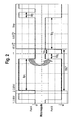
- FIG. 6 is also indicated by the reference numeral 60 of the initialization.
- FIG. 6 shows further that after the first start-up pulse 70 is transferred to the control mode with evaluation of the counter-voltage.
- the starting pulse 70 is followed by the demagnetizing pulse 80 in the opposite direction, followed by the time interval tx 1 , which is identified by the reference numeral 90. Due to the subsequent commutation, in the following interval Port A is energized, the demagnetization is carried out by means of Port B, and then again the time period tx n between the times 50 and 52 according to FIG FIG. 4 performed.
- the engine control according to the invention makes it possible to omit a sensor, for example a Hall sensor on the engine. Furthermore, it is possible according to the invention to dispense with additional electronics for fan control and to integrate these in the device control with.
- a blocking and / or a speed change can be detected and evaluated. Also, an adjustment of the speed is possible. In a further embodiment of the invention can be provided that the direction of rotation is adjustable.
Landscapes
- Engineering & Computer Science (AREA)
- Power Engineering (AREA)
- Control Of Motors That Do Not Use Commutators (AREA)
Applications Claiming Priority (1)
| Application Number | Priority Date | Filing Date | Title |
|---|---|---|---|
| DE202007013726U DE202007013726U1 (de) | 2007-10-01 | 2007-10-01 | Einrichtung zur Regelung eines Elektromotors |
Publications (2)
| Publication Number | Publication Date |
|---|---|
| EP2045908A2 true EP2045908A2 (fr) | 2009-04-08 |
| EP2045908A3 EP2045908A3 (fr) | 2013-12-04 |
Family
ID=40365600
Family Applications (1)
| Application Number | Title | Priority Date | Filing Date |
|---|---|---|---|
| EP08017233.1A Withdrawn EP2045908A3 (fr) | 2007-10-01 | 2008-09-30 | Dispositif destiné au réglage d'un moteur électrique |
Country Status (2)
| Country | Link |
|---|---|
| EP (1) | EP2045908A3 (fr) |
| DE (1) | DE202007013726U1 (fr) |
Cited By (2)
| Publication number | Priority date | Publication date | Assignee | Title |
|---|---|---|---|---|
| EP3282575A1 (fr) * | 2016-08-11 | 2018-02-14 | Melexis Bulgaria Ltd. | Circuit d'entraînement de moteur à phase unique et procédé d'entraînement d'un moteur à phase unique |
| IT201700018513A1 (it) * | 2017-02-20 | 2018-08-20 | Elica Spa | Metodo per controllare a sei passi di commutazione un inverter trifase configurato per azionare un motore elettrico brushless |
Families Citing this family (1)
| Publication number | Priority date | Publication date | Assignee | Title |
|---|---|---|---|---|
| US9166507B2 (en) * | 2013-12-26 | 2015-10-20 | Silicon Laboratories Inc. | Sensing a back electromotive force of a motor |
Family Cites Families (4)
| Publication number | Priority date | Publication date | Assignee | Title |
|---|---|---|---|---|
| US5845045A (en) * | 1993-11-28 | 1998-12-01 | Papst-Motoren Gmbh & Co. Kg | Method and apparatus for DC motor speed control |
| DE10308859A1 (de) * | 2003-02-27 | 2004-09-16 | Melexis Gmbh | Verfahren zur leistungsoptimalen Ansteuerung von BLDC-Motoren |
| DE10314426B4 (de) * | 2003-03-31 | 2006-09-14 | Junghans Uhren Gmbh | Verfahren zur Dreherkennung eines wenigstens einen Zeiger einer Uhr antreibenden Schrittmotors |
| US20080157707A1 (en) * | 2005-03-04 | 2008-07-03 | Ebm-Papst St. Georgen Gmbh & Co. Kg | Electric Motor And Method Of Controllling Said Motor |
-
2007
- 2007-10-01 DE DE202007013726U patent/DE202007013726U1/de not_active Expired - Lifetime
-
2008
- 2008-09-30 EP EP08017233.1A patent/EP2045908A3/fr not_active Withdrawn
Cited By (4)
| Publication number | Priority date | Publication date | Assignee | Title |
|---|---|---|---|---|
| EP3282575A1 (fr) * | 2016-08-11 | 2018-02-14 | Melexis Bulgaria Ltd. | Circuit d'entraînement de moteur à phase unique et procédé d'entraînement d'un moteur à phase unique |
| US10461673B2 (en) | 2016-08-11 | 2019-10-29 | Melexis Bulgaria Ltd. | Single phase motor drive circuit and a method of driving a single phase motor |
| IT201700018513A1 (it) * | 2017-02-20 | 2018-08-20 | Elica Spa | Metodo per controllare a sei passi di commutazione un inverter trifase configurato per azionare un motore elettrico brushless |
| EP3364537A1 (fr) * | 2017-02-20 | 2018-08-22 | ELICA S.p.A. | Procédé de commande d'un inverseur triphasé avec six-step commutation, conçu pour entraîner un moteur électrique sans balais |
Also Published As
| Publication number | Publication date |
|---|---|
| EP2045908A3 (fr) | 2013-12-04 |
| DE202007013726U1 (de) | 2009-02-19 |
Similar Documents
| Publication | Publication Date | Title |
|---|---|---|
| EP0993108B1 (fr) | Procédé et dispositif pour déterminer la position du rotor d'un moteur synchrone | |
| DE112007001630B4 (de) | Verfahren und Vorrichtung zur Bestimmung der Rotorposition bei einem bürstenlosen und sensorlosen Elektromotor | |
| DE10326606A1 (de) | Verfahren zur Kommutierung eines bürstenlosen Gleichstrommotors | |
| EP1727268A2 (fr) | Procédé pour faire fonctionner un moteur à commutation électronique et moteur pour la mise en oeuvre dudit procédé | |
| DE19860446A1 (de) | Verfahren zur Regelung eines spannungs-/frequenzumrichtergesteuerten Mehrphasen-Permanentmagnetmotors | |
| EP2158673A1 (fr) | Procédé d'exploitation d'un moteur à commutation électronique monophasé sur une source de tension continue et moteur pour mettre un tel procédé en oeuvre | |
| DE102008025706A1 (de) | Antriebsvorrichtung für einen bürstenlosen Motor | |
| DE19936755A1 (de) | Verfahren zum Starten von Brushless DC-Motoren | |
| DE102013218041A1 (de) | Verfahren zum Betreiben eines Elektromotors | |
| EP2278339B1 (fr) | Système avec un moteur à commutation électronique monophasé et avec une unité de calcul electronique | |
| EP2045908A2 (fr) | Dispositif destiné au réglage d'un moteur électrique | |
| EP2567456B1 (fr) | Procédé et dispositif de commande pour faire fonctionner un moteur à courant continu triphasé sans balai | |
| DE102014107949A1 (de) | Verfahren und Vorrichtung zur Erkennung eines Nulldurchgangs eines Stroms durch einen Strang eines bürstenlosen Gleichstrom- motors | |
| EP2343797A2 (fr) | Moteur monophasé commuté de manière électronique | |
| DE102009013374B4 (de) | Rotor für Elektromotoren, Permanentmagnet für einen solchen Rotor sowie elektrische Maschine mit einem Rotor | |
| EP1443635B1 (fr) | Procédé de contrôle d'un angle d'allumage et moteur électrique alimenté en courant monophasé | |
| DE4438569A1 (de) | Verfahren und Schaltungsanordnung zum Anfahren eines elektronisch kommutierten, einständigen Gleichstrommotors | |
| DE102006004313A1 (de) | Verfahren zur Steuerung eines Gleichspannungs-Elektromotors | |
| DE102013014481A1 (de) | Verfahren zum Betreiben eines Elektromotors | |
| DE102017127410A1 (de) | Verfahren und Schaltungsanordnung zur Ermittlung der Stellung eines Rotors eines Elektromotors | |
| EP1136828B1 (fr) | Procédé de mesure de courant | |
| EP1903289B1 (fr) | Appareil de réfrigération et/ou de congélation | |
| EP1576721A1 (fr) | Ensemble circuit et procede pour faire fonctionner un moteur electrique sur un reseau a tension continue | |
| DE102018119723A1 (de) | Verfahren zum Ansteuern eines Elektromotors und Elektromotor | |
| DE102019120888A1 (de) | EC-Motor mit reduziertem Energieverbrauch im Stillstand-Modus |
Legal Events
| Date | Code | Title | Description |
|---|---|---|---|
| PUAI | Public reference made under article 153(3) epc to a published international application that has entered the european phase |
Free format text: ORIGINAL CODE: 0009012 |
|
| AK | Designated contracting states |
Kind code of ref document: A2 Designated state(s): AT BE BG CH CY CZ DE DK EE ES FI FR GB GR HR HU IE IS IT LI LT LU LV MC MT NL NO PL PT RO SE SI SK TR |
|
| AX | Request for extension of the european patent |
Extension state: AL BA MK RS |
|
| PUAL | Search report despatched |
Free format text: ORIGINAL CODE: 0009013 |
|
| AK | Designated contracting states |
Kind code of ref document: A3 Designated state(s): AT BE BG CH CY CZ DE DK EE ES FI FR GB GR HR HU IE IS IT LI LT LU LV MC MT NL NO PL PT RO SE SI SK TR |
|
| AX | Request for extension of the european patent |
Extension state: AL BA MK RS |
|
| RIC1 | Information provided on ipc code assigned before grant |
Ipc: H02P 6/18 20060101AFI20131025BHEP Ipc: H02P 6/14 20060101ALI20131025BHEP |
|
| 17P | Request for examination filed |
Effective date: 20140604 |
|
| AKX | Designation fees paid |
Designated state(s): DE ES FR IT |
|
| STAA | Information on the status of an ep patent application or granted ep patent |
Free format text: STATUS: THE APPLICATION IS DEEMED TO BE WITHDRAWN |
|
| 18D | Application deemed to be withdrawn |
Effective date: 20160401 |