EP2046623B1 - Systemé comprenant un compresseur et une charge dans un véhicule automobile - Google Patents
Systemé comprenant un compresseur et une charge dans un véhicule automobile Download PDFInfo
- Publication number
- EP2046623B1 EP2046623B1 EP07786191A EP07786191A EP2046623B1 EP 2046623 B1 EP2046623 B1 EP 2046623B1 EP 07786191 A EP07786191 A EP 07786191A EP 07786191 A EP07786191 A EP 07786191A EP 2046623 B1 EP2046623 B1 EP 2046623B1
- Authority
- EP
- European Patent Office
- Prior art keywords
- power
- compressor
- pump
- pumping
- consumer
- Prior art date
- Legal status (The legal status is an assumption and is not a legal conclusion. Google has not performed a legal analysis and makes no representation as to the accuracy of the status listed.)
- Not-in-force
Links
- 238000005086 pumping Methods 0.000 claims abstract description 56
- 238000010521 absorption reaction Methods 0.000 claims abstract description 9
- 238000002485 combustion reaction Methods 0.000 claims description 30
- 238000007906 compression Methods 0.000 claims description 27
- 230000006835 compression Effects 0.000 claims description 18
- 238000006073 displacement reaction Methods 0.000 claims description 3
- 239000012530 fluid Substances 0.000 description 7
- 230000008878 coupling Effects 0.000 description 6
- 238000010168 coupling process Methods 0.000 description 6
- 238000005859 coupling reaction Methods 0.000 description 6
- 230000001419 dependent effect Effects 0.000 description 3
- 230000009467 reduction Effects 0.000 description 3
- 230000005540 biological transmission Effects 0.000 description 1
- 238000007599 discharging Methods 0.000 description 1
- 230000000694 effects Effects 0.000 description 1
- 210000003746 feather Anatomy 0.000 description 1
- 239000000463 material Substances 0.000 description 1
- 238000000034 method Methods 0.000 description 1
- 238000012986 modification Methods 0.000 description 1
- 230000004048 modification Effects 0.000 description 1
- 230000008569 process Effects 0.000 description 1
- 230000003319 supportive effect Effects 0.000 description 1
- 239000000725 suspension Substances 0.000 description 1
- 230000001360 synchronised effect Effects 0.000 description 1
Images

Classifications
-
- B—PERFORMING OPERATIONS; TRANSPORTING
- B62—LAND VEHICLES FOR TRAVELLING OTHERWISE THAN ON RAILS
- B62D—MOTOR VEHICLES; TRAILERS
- B62D5/00—Power-assisted or power-driven steering
- B62D5/06—Power-assisted or power-driven steering fluid, i.e. using a pressurised fluid for most or all the force required for steering a vehicle
- B62D5/062—Details, component parts
- B62D5/063—Pump driven by vehicle engine
-
- B—PERFORMING OPERATIONS; TRANSPORTING
- B60—VEHICLES IN GENERAL
- B60K—ARRANGEMENT OR MOUNTING OF PROPULSION UNITS OR OF TRANSMISSIONS IN VEHICLES; ARRANGEMENT OR MOUNTING OF PLURAL DIVERSE PRIME-MOVERS IN VEHICLES; AUXILIARY DRIVES FOR VEHICLES; INSTRUMENTATION OR DASHBOARDS FOR VEHICLES; ARRANGEMENTS IN CONNECTION WITH COOLING, AIR INTAKE, GAS EXHAUST OR FUEL SUPPLY OF PROPULSION UNITS IN VEHICLES
- B60K25/00—Auxiliary drives
-
- F—MECHANICAL ENGINEERING; LIGHTING; HEATING; WEAPONS; BLASTING
- F04—POSITIVE - DISPLACEMENT MACHINES FOR LIQUIDS; PUMPS FOR LIQUIDS OR ELASTIC FLUIDS
- F04C—ROTARY-PISTON, OR OSCILLATING-PISTON, POSITIVE-DISPLACEMENT MACHINES FOR LIQUIDS; ROTARY-PISTON, OR OSCILLATING-PISTON, POSITIVE-DISPLACEMENT PUMPS
- F04C11/00—Combinations of two or more machines or pumps, each being of rotary-piston or oscillating-piston type; Pumping installations
- F04C11/005—Combinations of two or more machines or pumps, each being of rotary-piston or oscillating-piston type; Pumping installations of dissimilar working principle
-
- F—MECHANICAL ENGINEERING; LIGHTING; HEATING; WEAPONS; BLASTING
- F04—POSITIVE - DISPLACEMENT MACHINES FOR LIQUIDS; PUMPS FOR LIQUIDS OR ELASTIC FLUIDS
- F04C—ROTARY-PISTON, OR OSCILLATING-PISTON, POSITIVE-DISPLACEMENT MACHINES FOR LIQUIDS; ROTARY-PISTON, OR OSCILLATING-PISTON, POSITIVE-DISPLACEMENT PUMPS
- F04C2/00—Rotary-piston machines or pumps
- F04C2/30—Rotary-piston machines or pumps having the characteristics covered by two or more groups F04C2/02, F04C2/08, F04C2/22, F04C2/24 or having the characteristics covered by one of these groups together with some other type of movement between co-operating members
- F04C2/34—Rotary-piston machines or pumps having the characteristics covered by two or more groups F04C2/02, F04C2/08, F04C2/22, F04C2/24 or having the characteristics covered by one of these groups together with some other type of movement between co-operating members having the movement defined in groups F04C2/08 or F04C2/22 and relative reciprocation between the co-operating members
- F04C2/344—Rotary-piston machines or pumps having the characteristics covered by two or more groups F04C2/02, F04C2/08, F04C2/22, F04C2/24 or having the characteristics covered by one of these groups together with some other type of movement between co-operating members having the movement defined in groups F04C2/08 or F04C2/22 and relative reciprocation between the co-operating members with vanes reciprocating with respect to the inner member
- F04C2/3441—Rotary-piston machines or pumps having the characteristics covered by two or more groups F04C2/02, F04C2/08, F04C2/22, F04C2/24 or having the characteristics covered by one of these groups together with some other type of movement between co-operating members having the movement defined in groups F04C2/08 or F04C2/22 and relative reciprocation between the co-operating members with vanes reciprocating with respect to the inner member the inner and outer member being in contact along one line or continuous surface substantially parallel to the axis of rotation
- F04C2/3442—Rotary-piston machines or pumps having the characteristics covered by two or more groups F04C2/02, F04C2/08, F04C2/22, F04C2/24 or having the characteristics covered by one of these groups together with some other type of movement between co-operating members having the movement defined in groups F04C2/08 or F04C2/22 and relative reciprocation between the co-operating members with vanes reciprocating with respect to the inner member the inner and outer member being in contact along one line or continuous surface substantially parallel to the axis of rotation the surfaces of the inner and outer member, forming the working space, being surfaces of revolution
-
- F—MECHANICAL ENGINEERING; LIGHTING; HEATING; WEAPONS; BLASTING
- F04—POSITIVE - DISPLACEMENT MACHINES FOR LIQUIDS; PUMPS FOR LIQUIDS OR ELASTIC FLUIDS
- F04C—ROTARY-PISTON, OR OSCILLATING-PISTON, POSITIVE-DISPLACEMENT MACHINES FOR LIQUIDS; ROTARY-PISTON, OR OSCILLATING-PISTON, POSITIVE-DISPLACEMENT PUMPS
- F04C23/00—Combinations of two or more pumps, each being of rotary-piston or oscillating-piston type, specially adapted for elastic fluids; Pumping installations specially adapted for elastic fluids; Multi-stage pumps specially adapted for elastic fluids
- F04C23/005—Combinations of two or more pumps, each being of rotary-piston or oscillating-piston type, specially adapted for elastic fluids; Pumping installations specially adapted for elastic fluids; Multi-stage pumps specially adapted for elastic fluids of dissimilar working principle
-
- F—MECHANICAL ENGINEERING; LIGHTING; HEATING; WEAPONS; BLASTING
- F04—POSITIVE - DISPLACEMENT MACHINES FOR LIQUIDS; PUMPS FOR LIQUIDS OR ELASTIC FLUIDS
- F04C—ROTARY-PISTON, OR OSCILLATING-PISTON, POSITIVE-DISPLACEMENT MACHINES FOR LIQUIDS; ROTARY-PISTON, OR OSCILLATING-PISTON, POSITIVE-DISPLACEMENT PUMPS
- F04C2270/00—Control; Monitoring or safety arrangements
- F04C2270/02—Power
Definitions
- the invention relates to a system having a compressor and a consumer coupled to and drawing power from a power train, the compressor performing an expansion stroke and a compression stroke during operation. Furthermore, the invention relates to a pump having at least one pumping performance during a pumping pump chamber, wherein the pump further comprises at least one pump chamber, which provides no pumping power during pump operation, and wherein the pump disposed inside the pump rotor and a Exhaust port and a suction port comprising stator.
- compressors are used to procure compressed air for brakes, air suspension, transmissions, etc.
- the compressor is driven by an internal combustion engine of the motor vehicle via a drive train, which can be interrupted by means of a coupling device to relieve the internal combustion engine, if the boundary conditions allow.
- a power steering device also called power steering, equipped, which consists essentially of a power steering pump or hydraulic pump, such as an oil pump, and a hydraulic circuit through which the hydraulic pump coupled to a hydraulic linkage of a steering linkage Lenkhiltevorricntung supplies.
- a power steering pump or hydraulic pump such as an oil pump
- a hydraulic circuit through which the hydraulic pump coupled to a hydraulic linkage of a steering linkage Lenkhiltevorricntung supplies.
- an auxiliary power is generated, which is applied by means of suitable mechanical means on the steering wheel supportive.
- the hydraulic pump is often driven indirectly, ie indirectly, by the drive train of the internal combustion engine.
- the compressor is arranged in the drive train between the internal combustion engine and the hydraulic pump, wherein the compressor in turn drives the hydraulic pump as a consumer.
- compressors show an uneven course of the drive torque required for the compressor operation or the drive power required for the compressor operation, the drive torque or the drive power being provided by the internal combustion engine.
- the drive torque required for the compressor operation is particularly high compared to an expansion operation or expansion stroke. This is especially noticeable in piston compressors with at least one cylinder.
- the driving torque required for the compression operation for the compressor operation increases with the advance of the piston in the direction of top dead center in the cylinder and finally reaches a peak value in a region near top dead center, hereinafter referred to as torque peak or peak power.
- the torque peak causes repercussions on the internal combustion engine, for example on the gear train of the internal combustion engine.
- disturbances of the precise running of the camshaft can be caused. Therefore, a constant or uniform course of the torque or the power is sought, which provides or the internal combustion engine.
- an increased drive torque or an increased drive power of the internal combustion engine is required if in addition to the compressor, a power steering pump or hydraulic pump must be driven, which is located in the same drive train of the compressor.
- the coupling device provided in the drive train of the internal combustion engine must be designed according to the maximum transmitted drive torque or the maximum supplied drive power of the internal combustion engine.
- the WO 2005/042976 A which shows a pump according to the preamble of claim 7, discloses a pump with two pump chambers, wherein a first pumping chamber provides a pumping power, while a second pumping chamber via a valve means is switchably connectable to a suction slot. In particular, this makes it possible to selectively connect and disconnect the volume flow of the second pump chamber.
- the system according to the invention builds on the generic state of the art in that the consumer comprises means which are provided for receiving a power provided by the drive train as a function of a required for a compressor operation, fed from the drive train to the compressor Decrease power in the compression stroke when the required for the compressor operation power in the compression stroke exceeds a threshold or reaches a peak power, so that a course of the total power from the power required for the compressor operation and by the consumer absorbed power during a compression stroke of the compressor is substantially constant.
- the compressor basically has a very non-uniform course of the drive power required for the compressor operation or the drive torque required for the compressor operation in compressor operation.
- the system according to the invention can be further developed in that the consumer is suitable for recording the power provided to him reduce when a curve of the power required for the compressor operation increases above a predetermined threshold or reaches a range of a maximum power.
- the threshold value By setting the threshold value, the overall torque curve or the overall power curve in the drive train is prevented from exceeding a maximum permissible value, at the same time avoiding a power peak or a torque peak in the drive train.
- the height of the threshold value is determined in such a way that advantageously effects on the drive train, for example on an internal combustion engine located in the drive train, are largely prevented.
- the system according to the invention can be developed such that the power required for the compressor operation in a compression process or a compression stroke exceeds the threshold value or reaches its maximum performance.
- a very high torque or a very high drive power for driving the compressor may be required.
- the high drive torque which is a very high torque peak just before
- the system according to the invention can also be designed such that the consumer comprises a pump, in particular a power steering pump or a hydraulic pump, which is suitable for performing a pumping operation in which the power provided is provided, and a no or in Dependent on operating characteristics of the compressor reduced pumping yielding operation in which no or a reduced absorption of the power provided takes place to perform.
- the pump located in the drive train which usually has a uniform torque curve or power curve, is adapted to the course of the required for the compressor operation, supplied power to achieve the above-mentioned constant course of the overall performance.
- the system according to the invention is designed in such a way that the pump comprises a displacement pump, in particular a vane pump or a piston pump, in which at least one is not or depending on operating characteristics of the compressor reduced pump power performing pump chamber is formed, with no or a reduced absorption of the power provided in a pump operation takes place, wherein the pump further comprises at least one pumping performance pump chamber, with which takes place in a pump operation recording the power provided.
- a displacement pump in particular a vane pump or a piston pump
- the pump further comprises at least one pumping performance pump chamber, with which takes place in a pump operation recording the power provided.
- the vane pump has more than 6 pump chambers, of which a part of the chambers can be placed in a state of "no pumping" in order to reduce the power consumption during the operation of this pump chamber and thus to achieve the abovementioned compensation of the peak torque ,
- This can be done, for example, by an increased chamber volume in a vane pump, which can be increased, for example in the case of the vane pump by reshaping the rotor, ie on the one side flattened rotor with respect to the rotor axis, on the flattened side of the pumping pumping pump chamber in part formed.
- the system according to the invention can also be further developed in that the compressor is driven by a drive train of an internal combustion engine and the load by a drive train of the compressor, wherein optionally a clutch device is arranged in the drive train of the internal combustion engine.
- This development proves to be particularly advantageous because the engine provides the compressor with a constant course of the drive torque or a constant course of the drive power without driving torque increases due to the compression process occur, causing problems in the gear train of the engine and disturbances of the precise running of the camshaft due the compensation of the torque peak can be avoided.
- the system according to the invention makes it possible to use a coupling device, such as a shut-down clutch, to reduce its size and thus to reduce the costs incurred because the coupling device is designed for the maximum drive torque of the compressor or the torque peak.
- a coupling device such as a shut-down clutch
- the arrangement mentioned here corresponds to a series arrangement of motor, compressor and consumer.
- a parallel arrangement of compressor and consumer or other arrangements are also conceivable, as long as they are coupled to the same drive train.
- the pump according to the invention builds on the state of the art in that during the pumping operation no Pumping performance pumping chamber is limited on the rotor side of the rotor having a flattened portion in this area that the rotor does not make contact with the stator between the discharge port and the suction port when the flattened portion of the rotor faces the discharge port and the suction port. Analogously, this applies to the advantages mentioned in connection with the power steering pump or hydraulic pump.
- FIG. 1 shows a schematic representation of the system according to the invention.
- An internal combustion engine 10 of a motor vehicle is coupled to a compressor or compressor 16 via a drive train 14.
- the compressor 16 is provided for example for compressed air procurement for different, unspecified components in the motor vehicle.
- a shut-off clutch or a clutch device 12 is arranged in the drive train 14 between the internal combustion engine 10 and the compressor 16.
- the coupling device 12 is used to couple the compressor 16 to the engine 10 and to decouple from this.
- the compressor 16 is decoupled from the drive train 14 of the internal combustion engine 10 when operation of the compressor 16 is no longer required and the vehicle conditions bsw. Boundary conditions allow this.
- the compressor 16 may be a reciprocating compressor with one or more cylinders in particular embodiments; but there are also other types conceivable.
- the compressor 16 is coupled to a load 20 via a drive train 18.
- the consumer 20 is in this embodiment, a power steering pump or a hydraulic pump, which is associated with a power steering or a power steering device.
- the hydraulic pump may be a positive displacement pump, such as a vane pump or a piston pump.
- the hydraulic pump has two in FIG. 1 schematically illustrated pump chambers 22 and 24.
- the pumping chamber 24 is a pumping chamber providing a pumping power, with which a fluid in a hydraulic circuit (not shown) of the power steering device is conveyed. If this pump chamber 24 is in operation, the pump receives a drive power from the compressor 16 via the drive train 18.
- the pump chamber 22, however, is designed in this embodiment such that it provides no pumping power. If this pump chamber 22 is in operation, the pump does not receive any drive power from the compressor 16 via the drive train 18.
- the pumping power of this pumping chamber 22 may also be reduced and need not be set to near zero.
- the extent of the reduction of the pumping power can be used, for example, depending on the In the drive train of the internal combustion engine 10 located compressor 16 or other components arranged there are set.
- the extent of the reduction in the pumping capacity of the pump chamber 22 depends on various factors such as the operating characteristics (torque curve, etc.) of the compressor 16 and the other components.
- FIG. 1 only two different pumping chambers are shown, however, a plurality of different pumping chambers of the aforementioned type may be provided.
- compressor 16 and consumer 20 are not mandatory. Essential is the fact that the compressor 16 and the consumer are coupled to the same drive train. Thus, it is conceivable that the consumer instead of the drive train 18 is directly coupled to the drive train 14 of the engine 10.
- the internal combustion engine 10 drives the compressor 16 via the drive train 14.
- the clutch device 12 is engaged, so that the drive torque of the engine 10 is transmitted to the compressor 16 and the drive power of the internal combustion engine 10 is delivered to the compressor.
- the internal combustion engine 10 provides a drive power that is required both for the operation of the compressor 16 and for the operation of the consumer 20, since the consumer 20, as in FIG. 1 shown coupled to the compressor 16.
- the clutch device 12 can also be disengaged if the operating conditions of the motor vehicle or the boundary conditions allow this and the compressor is not to be driven. In the following, however, it is assumed that a clutch device 12, which transmits in engagement and thus a drive torque.
- the compressor 16 performs an expansion operation and a compression operation during operation.
- this carries out a stroke movement of a piston (not shown) through which, for example, compressed air for a compressed air system, which will not be described in greater detail, is procured.
- a piston not shown
- the compression operation that is, as the piston progresses from a bottom dead center toward a top dead center, the progression of the torque / power required for compressor operation in the powertrain 14 behaves as discussed below.
- a reciprocating compressor with only one piston / cylinder is assumed below.
- the consumer 20 is provided on the drive train 18 of the compressor 16 so that it lowers its power consumption, such as the course of the torque required for the compressor operation in the Compression process exceeds a threshold or reaches a peak torque.
- the motor drive torque in the powertrain 14, which is a superposition of the torque required for compressor operation and the torque of the load 20 is maintained substantially constant, or the aforementioned power or torque peak is compensated due to the reduced power consumption of the load , Consequently, a virtually uniform or constant course of the torque transmitted by the internal combustion engine 10 or the output drive power of the internal combustion engine 10 is provided.
- the consumer 20 which is in the particular embodiment, the power steering pump or hydraulic pump, thus operates during the compression process and from exceeding the threshold exactly the pump chamber, which provides no pump power, causing the Power consumption of the hydraulic pump is reduced. Consequently, the course of the torque or the drive power of the internal combustion engine 10 kept constant or the torque peak is compensated. If the compressor 16 is no longer in the compression process, but, for example, in the expansion process in which the course of the power required for the compressor operation falls below the predetermined threshold or passes through no peak power, the pump operates the pump chamber 22, which provides and promotes a pumping power Accordingly, the fluid, whereby the power consumption of the consumer 20 is increased.
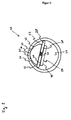
- FIG. 2 shows a particular embodiment of the consumer 20 according to FIG. 1
- the hydraulic pump or power steering pump forming the consumer 20 is a vane pump according to the invention, which is modified in such a way that it can carry out the above-mentioned different operations, ie an operation providing a pumping power and an operation providing no pumping power.
- the vane pump is shown with 3 pumping chambers, however, modified vane pumps with only 2 or more than 3 pumping chambers of the above mentioned type can be used.
- the vane pump has a rotor 26 and a stator 30.
- the rotor 26 is formed substantially cylindrical and rotatably supported about its longitudinal axis in the stator 30.
- On a first side 40 of the rotor 26 is flattened, that is, that on the first side 40, seen in the axial direction or in the direction of the axis of rotation, a circular segment or circle segment of the Rotor 26 is removed, wherein the rotor 26 forms a flattened portion on this side.
- the rotor 26 contacts with a contact portion 44, the stator 30, which is located on a second side 42 of the rotor 26, which faces away from the side 40 of the rotor 26.
- a guide 38 is formed, which is perpendicular to the axis of rotation and through the rotor 26.
- this guide 38 extends through the axis of rotation, so that the first side 40 with respect to the guide 38 has the flattened portion of the rotor 26 and the second side 42 with respect to the guide 38, the contact portion 44 of the rotor 26.
- two rotary valves 28 are arranged, which are held by means of a spring 36 and biased against the stator 30. The spring is firmly fixed in the rotor 26. Therefore, the rotor 26, together with the stator 30, the contact portion 44 of the stator 30 and the rotor 26 and the rotary valves 28 forms different pump chambers 22 and 24.
- FIG. 2 the space within the stator 30 is divided by the rotor 26, in particular the contact portion 44 of the rotor 26 with the stator 30, and the rotary valve into different pump chambers 22 and 24.
- the pump chamber 24 is a pump chamber providing no pumping power
- the pump chambers 22 are pumping pump chambers. This is due to the enlarged Chamber space due to the material removal or flattening or the flattened portion of the rotor 26 causes.
- the rotor 26 rotates about its axis of rotation, for example in the right-hand direction, that is counterclockwise. Characterized in that the rotary valves 28 are continuously in contact with the stator 30 due to the bias of the spring 36 and seal a gap therebetween, the fluid contained in the pump chamber 22 is conveyed to the discharge port 32. Furthermore, the other pump chamber 22 sucks the fluid via the suction opening 34 due to the rotational movement of the rotor 26.
- the pump chamber 24, however, is formed by the particular configuration of the rotor 26 such that it can provide no pump power. This is because the rotor 26 is in a corresponding position, i.
- the rotor 26 in the situation in which the flattened portion of the rotor 26 faces the discharge port 32 and suction port 34, can not make contact with the stator 30 between the discharge port 32 and the suction port 34, i. the rotor 26 has no contact section 44 on the side forming the pump chamber 24.
- the ejection opening 32 and the suction opening 34 in the pump chamber 24 are permanently connected in a corresponding position of the rotor 26, whereby no fluid is conveyed and therefore no pumping power is provided. Accordingly, the power consumption of the pump is greatly reduced.
- this pump chamber 24 is now time with the compression process of the compressor 16 is matched or synchronized from above the above threshold.
- the pump does not provide pump power while the history of the drive power required for compressor operation has exceeded the threshold.
- the uniform torque curve of the vane pump over a certain crank angle of the rotor 26 is significantly reduced.
- the reduction takes place at the location of the transmitted to the compressor 16 maximum torque, with a uniform overall torque curve or a uniform overall drive power curve in the drive train 14 of the engine 10 is ensured or kept constant, as explained above.
Landscapes
- Engineering & Computer Science (AREA)
- Mechanical Engineering (AREA)
- General Engineering & Computer Science (AREA)
- Chemical & Material Sciences (AREA)
- Combustion & Propulsion (AREA)
- Transportation (AREA)
- Rotary Pumps (AREA)
- Compressors, Vaccum Pumps And Other Relevant Systems (AREA)
- Compressor (AREA)
- Reciprocating Pumps (AREA)
Claims (7)
- Système comprenant un compresseur (16) et un dispositif (20) consommateur, qui sont couplés à une chaîne (14, 18) d'entraînement et en tire de l'énergie, caractérisé en ce que le compresseur (16) effectue en fonctionnement une phase de détente et une phase de compression, dans lequel le compresseur (20) comprend des moyens qui sont prévus pour diminuer dans la phase de compression une absorption d'une puissance, qui est mise à sa disposition par la chaîne (14, 18) d'entraînement, en fonction d'une puissance apportée au compresseur (16) par la chaîne (14, 18) d'entraînement et qui est nécessaire pour un fonctionnement du compresseur, lorsque la puissance nécessaire pour le fonctionnement du compresseur dépasse une valeur de seuil dans la phase de compression ou atteint une pointe de puissance, de sorte qu'une courbe de la puissance totale, composée de la puissance nécessaire pour le fonctionnement du compresseur et de la puissance absorbée par le dispositif (20) consommateur, soit sensiblement constante pendant une phase de compression du compresseur (16).
- Système suivant la revendication 1, caractérisé en ce que le dispositif (20) consommateur est propre à diminuer son absorption de la puissance qui est mise à sa disposition, lorsqu'une courbe de la puissance nécessaire pour le fonctionnement du compresseur dépasse une valeur de seuil déterminée à l'avance ou atteint une plage d'un maximum de puissance.
- Système suivant la revendication 2, caractérisé en ce que la puissance nécessaire pour le fonctionnement du compresseur dépasse la valeur de seuil ou atteint sa valeur maximum dans une opération de compression ou dans une phase de compression.
- Système suivant l'une des revendications précédentes, caractérisé en ce que le dispositif (20) consommateur comprend une pompe, notamment une pompe d'assistance à la direction ou une pompe hydraulique, qui est propre à effectuer un fonctionnement apportant une puissance de pompage, pour laquelle s'effectue l'absorption de la puissance mise à disposition, et un fonctionnement n'apportant pas de la puissance de pompage ou apportant une puissance de pompage diminuée en fonction des propriétés de fonctionnement du compresseur (16), fonctionnement dans lequel une absorption de la puissance mise à disposition n'a pas lieu ou une absorption de la puissance mise à disposition a lieu d'une manière diminuée.
- Système suivant la revendication 4, caractérisé en ce que la pompe est une pompe volumétrique, notamment une pompe à palette ou une pompe à piston, dans laquelle est constituée une chambre (22) de pompe n'apportant pas de puissance de pompage ou apportant une puissance de pompage diminuée en fonction des propriétés du fonctionnement du compresseur (16), chambre par laquelle il ne se produit pas en fonctionnement de pompage une absorption de la puissance mise à disposition ou il se produit une absorption diminuée de la puissance mise à disposition, la pompe ayant en outre au moins une chambre (24) de pompe apportant une puissance de pompage, par laquelle dans un fonctionnement en pompage l'absorption de la puissance mise à disposition a lieu.
- Système suivant l'une des revendications précédentes, caractérisé en ce que le compresseur (16) est entraîné par une chaîne (14) d'entraînement d'un moteur (10) à combustion et le dispositif (10) consommateur est entraîné par une chaîne (18) d'entraînement du compresseur (16), un dispositif (12)
- Pompe qui a au moins une chambre (22) de pompe apportant une puissance de pompage pendant un fonctionnement de la pompe, la pompe ayant au moins une chambre (24) de pompe qui n'apporte pas de puissance de pompage pendant le fonctionnement de la pompe et dans laquelle la pompe comprend un rotor (26) disposé à l'intérieur de la pompe et un stator (30) ayant une ouverture (32) de refoulement et une ouverture (34) d'aspiration, caractérisée en ce que la chambre (24) de pompe n'apportant pas de puissance de pompage pendant que la pompe fonctionne, est délimitée du côté du rotor par le rotor (26) qui a dans cette zone un segment aplati, en ce que le rotor (26) ne ménage pas de contact avec le stator (30) entre l'ouverture (32) de refoulement et l'ouverture (34) d'aspiration, lorsque le segment aplati du rotor (26) est tourné vers l'ouverture (32) de refoulement et vers l'ouverture (34) d'aspiration.
Applications Claiming Priority (2)
| Application Number | Priority Date | Filing Date | Title |
|---|---|---|---|
| DE102006033428A DE102006033428A1 (de) | 2006-07-19 | 2006-07-19 | System mit einem Verdichter und einem Verbraucher in einem Kraftfahrzeug |
| PCT/EP2007/006421 WO2008009446A1 (fr) | 2006-07-19 | 2007-07-19 | Système comprenant un compresseur et une charge dans un véhicule automobile |
Publications (2)
| Publication Number | Publication Date |
|---|---|
| EP2046623A1 EP2046623A1 (fr) | 2009-04-15 |
| EP2046623B1 true EP2046623B1 (fr) | 2011-11-23 |
Family
ID=38657139
Family Applications (1)
| Application Number | Title | Priority Date | Filing Date |
|---|---|---|---|
| EP07786191A Not-in-force EP2046623B1 (fr) | 2006-07-19 | 2007-07-19 | Systemé comprenant un compresseur et une charge dans un véhicule automobile |
Country Status (8)
| Country | Link |
|---|---|
| US (1) | US8337169B2 (fr) |
| EP (1) | EP2046623B1 (fr) |
| JP (1) | JP2009543973A (fr) |
| CN (1) | CN101506026B (fr) |
| AT (1) | ATE534569T1 (fr) |
| BR (1) | BRPI0714715A2 (fr) |
| DE (1) | DE102006033428A1 (fr) |
| WO (1) | WO2008009446A1 (fr) |
Families Citing this family (5)
| Publication number | Priority date | Publication date | Assignee | Title |
|---|---|---|---|---|
| US8260494B2 (en) * | 2008-04-02 | 2012-09-04 | International Truck Intellectual Property Company, Llc | Method and apparatus to optimize energy efficiency of air compressor in vehicle air brake application |
| CA2723203C (fr) | 2008-06-04 | 2016-10-11 | Knorr-Bremse Systeme Fuer Nutzfahrzeuge Gmbh | Systeme de compresseur servant a l'alimentation en air comprime d'un vehicule utilitaire, et procede permettant de faire fonctionner un systeme de compresseur |
| EP3199809B1 (fr) * | 2016-01-28 | 2021-06-09 | ABB Schweiz AG | Procédé de commande pour un système de compresseur |
| CN111197541B (zh) * | 2019-12-31 | 2022-08-05 | 潍柴动力股份有限公司 | 车辆及其控制方法 |
| US20240191707A1 (en) * | 2022-12-13 | 2024-06-13 | Nott Company | Electric Pump And Compressor Assembly, Systems Comprising Same, And Methods Of Using Same |
Citations (1)
| Publication number | Priority date | Publication date | Assignee | Title |
|---|---|---|---|---|
| WO2005042976A1 (fr) * | 2003-10-29 | 2005-05-12 | Gkn Sinter Metals Holding Gmbh | Pompe a deux cylindres ou a plusieurs cylindres |
Family Cites Families (19)
| Publication number | Priority date | Publication date | Assignee | Title |
|---|---|---|---|---|
| US1341915A (en) * | 1919-06-27 | 1920-06-01 | John W B Ladd | Combined water and air pump for automobiles |
| US2655110A (en) * | 1951-01-11 | 1953-10-13 | William L Sanborn | Multiple pump |
| US3037455A (en) * | 1957-09-04 | 1962-06-05 | Ford Motor Co | Pumps |
| FR2493241A1 (fr) | 1980-11-04 | 1982-05-07 | Valeo | Dispositif d'equipement entraine par le moteur d'un vehicule automobile |
| US4634887A (en) * | 1985-06-24 | 1987-01-06 | General Electric Company | Load rate limiting means for a locomotive engine |
| JPH0455266Y2 (fr) * | 1988-04-28 | 1992-12-25 | ||
| US5195479A (en) * | 1991-03-01 | 1993-03-23 | Mazda Motor Corporation | Drive apparatus for one or more supplemental apparatuses driven by an internal combustion engine |
| FR2724881B1 (fr) | 1994-09-23 | 1997-01-03 | Renault | Dispositif d'entrainement des accessoires d'un moteur a combustion de vehicule automobile |
| DE19515895A1 (de) * | 1995-04-29 | 1996-10-31 | Bosch Gmbh Robert | Druckluft-Versorgungseinrichtung für Fahrzeug-Druckluftanlagen sowie Verfahren zum Steuern der Druckluft-Versorgungseinrichtung |
| JPH09144651A (ja) * | 1995-11-20 | 1997-06-03 | Toyota Autom Loom Works Ltd | 往復動型圧縮機 |
| NL1001855C2 (nl) | 1995-12-08 | 1997-06-10 | Doornes Transmissie Bv | Rotatiepomp. |
| US5918573A (en) * | 1997-05-02 | 1999-07-06 | Killion; David L. | Energy efficient fluid pump |
| JP3451951B2 (ja) * | 1998-07-24 | 2003-09-29 | 日産自動車株式会社 | パラレル・ハイブリッド車両の空調制御装置 |
| US6289878B1 (en) * | 1999-07-15 | 2001-09-18 | Caterpillar Inc. | Engine having multiple pumps driven by a single shaft |
| GB2356681A (en) * | 1999-11-29 | 2001-05-30 | Knorr Bremse Systeme | Anti-backlash, noise reducing gear wheel |
| JP2003254233A (ja) * | 2002-03-06 | 2003-09-10 | Toyota Industries Corp | 圧縮機 |
| ATE475538T1 (de) * | 2003-03-05 | 2010-08-15 | Brother Ind Ltd | Pumpe und tintenstrahldrucker |
| JP4090382B2 (ja) * | 2003-04-21 | 2008-05-28 | 株式会社日立製作所 | 筒内噴射式内燃機関の燃料供給装置 |
| DE102005013027A1 (de) * | 2005-03-22 | 2006-10-26 | Knorr-Bremse Systeme für Nutzfahrzeuge GmbH | Antriebsstrang für einen Kompressor und eine Hydraulikpumpe |
-
2006
- 2006-07-19 DE DE102006033428A patent/DE102006033428A1/de not_active Ceased
-
2007
- 2007-07-19 WO PCT/EP2007/006421 patent/WO2008009446A1/fr not_active Ceased
- 2007-07-19 CN CN200780031638XA patent/CN101506026B/zh not_active Expired - Fee Related
- 2007-07-19 AT AT07786191T patent/ATE534569T1/de active
- 2007-07-19 BR BRPI0714715-5A patent/BRPI0714715A2/pt not_active IP Right Cessation
- 2007-07-19 JP JP2009519872A patent/JP2009543973A/ja active Pending
- 2007-07-19 EP EP07786191A patent/EP2046623B1/fr not_active Not-in-force
-
2009
- 2009-01-16 US US12/355,575 patent/US8337169B2/en not_active Expired - Fee Related
Patent Citations (1)
| Publication number | Priority date | Publication date | Assignee | Title |
|---|---|---|---|---|
| WO2005042976A1 (fr) * | 2003-10-29 | 2005-05-12 | Gkn Sinter Metals Holding Gmbh | Pompe a deux cylindres ou a plusieurs cylindres |
Also Published As
| Publication number | Publication date |
|---|---|
| JP2009543973A (ja) | 2009-12-10 |
| EP2046623A1 (fr) | 2009-04-15 |
| CN101506026A (zh) | 2009-08-12 |
| ATE534569T1 (de) | 2011-12-15 |
| DE102006033428A1 (de) | 2008-01-31 |
| BRPI0714715A2 (pt) | 2013-04-09 |
| CN101506026B (zh) | 2011-08-17 |
| US20090120405A1 (en) | 2009-05-14 |
| WO2008009446A1 (fr) | 2008-01-24 |
| US8337169B2 (en) | 2012-12-25 |
Similar Documents
| Publication | Publication Date | Title |
|---|---|---|
| EP3421802B1 (fr) | Pompe à gaz avec limiteur de pression pour la réduction du couple de démarrage | |
| DE102008016499A1 (de) | Hydraulikfluid-Versorgungssystem mit einer Druckverzweigungs-Doppelpumpe für ein Mehrganggetriebe und Verfahren | |
| DE4229069A1 (de) | Taumelscheiben-kaeltemittelkompressor fuer ein kuehlsystem | |
| EP3504435B1 (fr) | Système hydrostatique et station de pompage pour un oléoduc ou un gazoduc | |
| EP2324245B1 (fr) | Machine à piston hydrostatique équipée d'un dispositif de réduction de pulsations | |
| EP3601797B1 (fr) | Compresseur à piston avec une zone de reglage étendu | |
| DE102016107447A1 (de) | Rotationspumpe mit Schmiernut im Dichtsteg | |
| EP3014103B1 (fr) | Pompe haute pression et système d'injection de carburant pourvu d'une pompe haute pression | |
| EP2046623A1 (fr) | Systemé comprenant un compresseur et une charge dans un véhicule automobile | |
| DE102010020690B4 (de) | Hydraulisches Antriebssystem | |
| WO2019101361A1 (fr) | Procédé pour faire fonctionner un compresseur à piston et compresseur à piston | |
| DE102015119263A1 (de) | Pumpe-Motor-Einheit | |
| WO2025119994A1 (fr) | Pompe à palettes à course unique réglable, procédé de fonctionnement de pompe à palettes et système de direction | |
| DE4135904A1 (de) | Kolbenpumpe, insbesondere radialkolbenpumpe | |
| DE102016221332A1 (de) | Hydrauliksystem | |
| DE102013007668B4 (de) | Hydraulisches Antriebssystem für zwei in etwa parallel angeordnete Zylinder | |
| DE102010009839A1 (de) | Regelbare Pumpe mit dreistufigem Stator | |
| EP3091230B1 (fr) | Machine a piston hydrostatique | |
| DE102009036021A1 (de) | Ventilgesteuerte Verdrängermaschine | |
| EP2409015A1 (fr) | Pompe haute pression | |
| DE19612598C2 (de) | Verstellbare, hydraulische Arbeitsmaschine | |
| DE102013200715A1 (de) | Schrägscheibenmaschine | |
| DE102020105172A1 (de) | Drehschieberpumpe | |
| DE102011115665A1 (de) | Ventilgesteuerte Hydromaschine | |
| DE102005061165A1 (de) | Antrieb für ein Nebenaggregat oder Hilfsaggregat eines Kraftfahrzeugs |
Legal Events
| Date | Code | Title | Description |
|---|---|---|---|
| PUAI | Public reference made under article 153(3) epc to a published international application that has entered the european phase |
Free format text: ORIGINAL CODE: 0009012 |
|
| 17P | Request for examination filed |
Effective date: 20090219 |
|
| AK | Designated contracting states |
Kind code of ref document: A1 Designated state(s): AT BE BG CH CY CZ DE DK EE ES FI FR GB GR HU IE IS IT LI LT LU LV MC MT NL PL PT RO SE SI SK TR |
|
| AX | Request for extension of the european patent |
Extension state: AL BA HR MK RS |
|
| 17Q | First examination report despatched |
Effective date: 20100707 |
|
| R17C | First examination report despatched (corrected) |
Effective date: 20100707 |
|
| GRAP | Despatch of communication of intention to grant a patent |
Free format text: ORIGINAL CODE: EPIDOSNIGR1 |
|
| GRAS | Grant fee paid |
Free format text: ORIGINAL CODE: EPIDOSNIGR3 |
|
| GRAA | (expected) grant |
Free format text: ORIGINAL CODE: 0009210 |
|
| DAX | Request for extension of the european patent (deleted) | ||
| AK | Designated contracting states |
Kind code of ref document: B1 Designated state(s): AT BE BG CH CY CZ DE DK EE ES FI FR GB GR HU IE IS IT LI LT LU LV MC MT NL PL PT RO SE SI SK TR |
|
| REG | Reference to a national code |
Ref country code: GB Ref legal event code: FG4D Free format text: NOT ENGLISH |
|
| REG | Reference to a national code |
Ref country code: CH Ref legal event code: EP |
|
| REG | Reference to a national code |
Ref country code: IE Ref legal event code: FG4D Free format text: LANGUAGE OF EP DOCUMENT: GERMAN |
|
| REG | Reference to a national code |
Ref country code: DE Ref legal event code: R096 Ref document number: 502007008727 Country of ref document: DE Effective date: 20120126 |
|
| REG | Reference to a national code |
Ref country code: NL Ref legal event code: VDEP Effective date: 20111123 |
|
| REG | Reference to a national code |
Ref country code: SE Ref legal event code: TRGR |
|
| LTIE | Lt: invalidation of european patent or patent extension |
Effective date: 20111123 |
|
| PG25 | Lapsed in a contracting state [announced via postgrant information from national office to epo] |
Ref country code: IS Free format text: LAPSE BECAUSE OF FAILURE TO SUBMIT A TRANSLATION OF THE DESCRIPTION OR TO PAY THE FEE WITHIN THE PRESCRIBED TIME-LIMIT Effective date: 20120323 Ref country code: LT Free format text: LAPSE BECAUSE OF FAILURE TO SUBMIT A TRANSLATION OF THE DESCRIPTION OR TO PAY THE FEE WITHIN THE PRESCRIBED TIME-LIMIT Effective date: 20111123 |
|
| PG25 | Lapsed in a contracting state [announced via postgrant information from national office to epo] |
Ref country code: GR Free format text: LAPSE BECAUSE OF FAILURE TO SUBMIT A TRANSLATION OF THE DESCRIPTION OR TO PAY THE FEE WITHIN THE PRESCRIBED TIME-LIMIT Effective date: 20120224 Ref country code: PT Free format text: LAPSE BECAUSE OF FAILURE TO SUBMIT A TRANSLATION OF THE DESCRIPTION OR TO PAY THE FEE WITHIN THE PRESCRIBED TIME-LIMIT Effective date: 20120323 Ref country code: SI Free format text: LAPSE BECAUSE OF FAILURE TO SUBMIT A TRANSLATION OF THE DESCRIPTION OR TO PAY THE FEE WITHIN THE PRESCRIBED TIME-LIMIT Effective date: 20111123 Ref country code: LV Free format text: LAPSE BECAUSE OF FAILURE TO SUBMIT A TRANSLATION OF THE DESCRIPTION OR TO PAY THE FEE WITHIN THE PRESCRIBED TIME-LIMIT Effective date: 20111123 Ref country code: NL Free format text: LAPSE BECAUSE OF FAILURE TO SUBMIT A TRANSLATION OF THE DESCRIPTION OR TO PAY THE FEE WITHIN THE PRESCRIBED TIME-LIMIT Effective date: 20111123 |
|
| REG | Reference to a national code |
Ref country code: IE Ref legal event code: FD4D |
|
| PG25 | Lapsed in a contracting state [announced via postgrant information from national office to epo] |
Ref country code: CY Free format text: LAPSE BECAUSE OF FAILURE TO SUBMIT A TRANSLATION OF THE DESCRIPTION OR TO PAY THE FEE WITHIN THE PRESCRIBED TIME-LIMIT Effective date: 20111123 |
|
| PG25 | Lapsed in a contracting state [announced via postgrant information from national office to epo] |
Ref country code: EE Free format text: LAPSE BECAUSE OF FAILURE TO SUBMIT A TRANSLATION OF THE DESCRIPTION OR TO PAY THE FEE WITHIN THE PRESCRIBED TIME-LIMIT Effective date: 20111123 Ref country code: CZ Free format text: LAPSE BECAUSE OF FAILURE TO SUBMIT A TRANSLATION OF THE DESCRIPTION OR TO PAY THE FEE WITHIN THE PRESCRIBED TIME-LIMIT Effective date: 20111123 Ref country code: SK Free format text: LAPSE BECAUSE OF FAILURE TO SUBMIT A TRANSLATION OF THE DESCRIPTION OR TO PAY THE FEE WITHIN THE PRESCRIBED TIME-LIMIT Effective date: 20111123 Ref country code: DK Free format text: LAPSE BECAUSE OF FAILURE TO SUBMIT A TRANSLATION OF THE DESCRIPTION OR TO PAY THE FEE WITHIN THE PRESCRIBED TIME-LIMIT Effective date: 20111123 Ref country code: BG Free format text: LAPSE BECAUSE OF FAILURE TO SUBMIT A TRANSLATION OF THE DESCRIPTION OR TO PAY THE FEE WITHIN THE PRESCRIBED TIME-LIMIT Effective date: 20120223 Ref country code: IE Free format text: LAPSE BECAUSE OF FAILURE TO SUBMIT A TRANSLATION OF THE DESCRIPTION OR TO PAY THE FEE WITHIN THE PRESCRIBED TIME-LIMIT Effective date: 20111123 |
|
| PG25 | Lapsed in a contracting state [announced via postgrant information from national office to epo] |
Ref country code: PL Free format text: LAPSE BECAUSE OF FAILURE TO SUBMIT A TRANSLATION OF THE DESCRIPTION OR TO PAY THE FEE WITHIN THE PRESCRIBED TIME-LIMIT Effective date: 20111123 Ref country code: RO Free format text: LAPSE BECAUSE OF FAILURE TO SUBMIT A TRANSLATION OF THE DESCRIPTION OR TO PAY THE FEE WITHIN THE PRESCRIBED TIME-LIMIT Effective date: 20111123 |
|
| PLBE | No opposition filed within time limit |
Free format text: ORIGINAL CODE: 0009261 |
|
| STAA | Information on the status of an ep patent application or granted ep patent |
Free format text: STATUS: NO OPPOSITION FILED WITHIN TIME LIMIT |
|
| 26N | No opposition filed |
Effective date: 20120824 |
|
| REG | Reference to a national code |
Ref country code: DE Ref legal event code: R097 Ref document number: 502007008727 Country of ref document: DE Effective date: 20120824 |
|
| BERE | Be: lapsed |
Owner name: KNORR-BREMSE SYSTEME FUR NUTZFAHRZEUGE G.M.B.H. Effective date: 20120731 |
|
| PG25 | Lapsed in a contracting state [announced via postgrant information from national office to epo] |
Ref country code: MC Free format text: LAPSE BECAUSE OF NON-PAYMENT OF DUE FEES Effective date: 20120731 |
|
| REG | Reference to a national code |
Ref country code: CH Ref legal event code: PL |
|
| GBPC | Gb: european patent ceased through non-payment of renewal fee |
Effective date: 20120719 |
|
| PG25 | Lapsed in a contracting state [announced via postgrant information from national office to epo] |
Ref country code: LI Free format text: LAPSE BECAUSE OF NON-PAYMENT OF DUE FEES Effective date: 20120731 Ref country code: CH Free format text: LAPSE BECAUSE OF NON-PAYMENT OF DUE FEES Effective date: 20120731 Ref country code: GB Free format text: LAPSE BECAUSE OF NON-PAYMENT OF DUE FEES Effective date: 20120719 Ref country code: ES Free format text: LAPSE BECAUSE OF FAILURE TO SUBMIT A TRANSLATION OF THE DESCRIPTION OR TO PAY THE FEE WITHIN THE PRESCRIBED TIME-LIMIT Effective date: 20120305 |
|
| PG25 | Lapsed in a contracting state [announced via postgrant information from national office to epo] |
Ref country code: BE Free format text: LAPSE BECAUSE OF NON-PAYMENT OF DUE FEES Effective date: 20120731 |
|
| PG25 | Lapsed in a contracting state [announced via postgrant information from national office to epo] |
Ref country code: FI Free format text: LAPSE BECAUSE OF FAILURE TO SUBMIT A TRANSLATION OF THE DESCRIPTION OR TO PAY THE FEE WITHIN THE PRESCRIBED TIME-LIMIT Effective date: 20111123 |
|
| PG25 | Lapsed in a contracting state [announced via postgrant information from national office to epo] |
Ref country code: MT Free format text: LAPSE BECAUSE OF FAILURE TO SUBMIT A TRANSLATION OF THE DESCRIPTION OR TO PAY THE FEE WITHIN THE PRESCRIBED TIME-LIMIT Effective date: 20111123 |
|
| REG | Reference to a national code |
Ref country code: AT Ref legal event code: MM01 Ref document number: 534569 Country of ref document: AT Kind code of ref document: T Effective date: 20120731 |
|
| PG25 | Lapsed in a contracting state [announced via postgrant information from national office to epo] |
Ref country code: AT Free format text: LAPSE BECAUSE OF NON-PAYMENT OF DUE FEES Effective date: 20120731 |
|
| PG25 | Lapsed in a contracting state [announced via postgrant information from national office to epo] |
Ref country code: TR Free format text: LAPSE BECAUSE OF FAILURE TO SUBMIT A TRANSLATION OF THE DESCRIPTION OR TO PAY THE FEE WITHIN THE PRESCRIBED TIME-LIMIT Effective date: 20111123 |
|
| PG25 | Lapsed in a contracting state [announced via postgrant information from national office to epo] |
Ref country code: LU Free format text: LAPSE BECAUSE OF NON-PAYMENT OF DUE FEES Effective date: 20120719 |
|
| PG25 | Lapsed in a contracting state [announced via postgrant information from national office to epo] |
Ref country code: HU Free format text: LAPSE BECAUSE OF FAILURE TO SUBMIT A TRANSLATION OF THE DESCRIPTION OR TO PAY THE FEE WITHIN THE PRESCRIBED TIME-LIMIT Effective date: 20070719 |
|
| REG | Reference to a national code |
Ref country code: FR Ref legal event code: PLFP Year of fee payment: 10 |
|
| PGFP | Annual fee paid to national office [announced via postgrant information from national office to epo] |
Ref country code: IT Payment date: 20160721 Year of fee payment: 10 Ref country code: DE Payment date: 20160721 Year of fee payment: 10 |
|
| PGFP | Annual fee paid to national office [announced via postgrant information from national office to epo] |
Ref country code: FR Payment date: 20160722 Year of fee payment: 10 Ref country code: SE Payment date: 20160721 Year of fee payment: 10 |
|
| REG | Reference to a national code |
Ref country code: DE Ref legal event code: R119 Ref document number: 502007008727 Country of ref document: DE |
|
| REG | Reference to a national code |
Ref country code: SE Ref legal event code: EUG |
|
| REG | Reference to a national code |
Ref country code: FR Ref legal event code: ST Effective date: 20180330 |
|
| PG25 | Lapsed in a contracting state [announced via postgrant information from national office to epo] |
Ref country code: SE Free format text: LAPSE BECAUSE OF NON-PAYMENT OF DUE FEES Effective date: 20170720 Ref country code: DE Free format text: LAPSE BECAUSE OF NON-PAYMENT OF DUE FEES Effective date: 20180201 |
|
| PG25 | Lapsed in a contracting state [announced via postgrant information from national office to epo] |
Ref country code: FR Free format text: LAPSE BECAUSE OF NON-PAYMENT OF DUE FEES Effective date: 20170731 |
|
| PG25 | Lapsed in a contracting state [announced via postgrant information from national office to epo] |
Ref country code: IT Free format text: LAPSE BECAUSE OF NON-PAYMENT OF DUE FEES Effective date: 20170719 |