EP3421802B1 - Pompe à gaz avec limiteur de pression pour la réduction du couple de démarrage - Google Patents
Pompe à gaz avec limiteur de pression pour la réduction du couple de démarrage Download PDFInfo
- Publication number
- EP3421802B1 EP3421802B1 EP18187866.1A EP18187866A EP3421802B1 EP 3421802 B1 EP3421802 B1 EP 3421802B1 EP 18187866 A EP18187866 A EP 18187866A EP 3421802 B1 EP3421802 B1 EP 3421802B1
- Authority
- EP
- European Patent Office
- Prior art keywords
- spring
- housing part
- gas pump
- sealing
- pump
- Prior art date
- Legal status (The legal status is an assumption and is not a legal conclusion. Google has not performed a legal analysis and makes no representation as to the accuracy of the status listed.)
- Active
Links
Images


Classifications
-
- F—MECHANICAL ENGINEERING; LIGHTING; HEATING; WEAPONS; BLASTING
- F04—POSITIVE - DISPLACEMENT MACHINES FOR LIQUIDS; PUMPS FOR LIQUIDS OR ELASTIC FLUIDS
- F04C—ROTARY-PISTON, OR OSCILLATING-PISTON, POSITIVE-DISPLACEMENT MACHINES FOR LIQUIDS; ROTARY-PISTON, OR OSCILLATING-PISTON, POSITIVE-DISPLACEMENT PUMPS
- F04C27/00—Sealing arrangements in rotary-piston pumps specially adapted for elastic fluids
- F04C27/02—Liquid sealing for high-vacuum pumps or for compressors
-
- F—MECHANICAL ENGINEERING; LIGHTING; HEATING; WEAPONS; BLASTING
- F04—POSITIVE - DISPLACEMENT MACHINES FOR LIQUIDS; PUMPS FOR LIQUIDS OR ELASTIC FLUIDS
- F04C—ROTARY-PISTON, OR OSCILLATING-PISTON, POSITIVE-DISPLACEMENT MACHINES FOR LIQUIDS; ROTARY-PISTON, OR OSCILLATING-PISTON, POSITIVE-DISPLACEMENT PUMPS
- F04C25/00—Adaptations of pumps for special use of pumps for elastic fluids
- F04C25/02—Adaptations of pumps for special use of pumps for elastic fluids for producing high vacuum
-
- F—MECHANICAL ENGINEERING; LIGHTING; HEATING; WEAPONS; BLASTING
- F04—POSITIVE - DISPLACEMENT MACHINES FOR LIQUIDS; PUMPS FOR LIQUIDS OR ELASTIC FLUIDS
- F04B—POSITIVE-DISPLACEMENT MACHINES FOR LIQUIDS; PUMPS
- F04B53/00—Component parts, details or accessories not provided for in, or of interest apart from, groups F04B1/00 - F04B23/00 or F04B39/00 - F04B47/00
- F04B53/16—Casings; Cylinders; Cylinder liners or heads; Fluid connections
-
- F—MECHANICAL ENGINEERING; LIGHTING; HEATING; WEAPONS; BLASTING
- F04—POSITIVE - DISPLACEMENT MACHINES FOR LIQUIDS; PUMPS FOR LIQUIDS OR ELASTIC FLUIDS
- F04C—ROTARY-PISTON, OR OSCILLATING-PISTON, POSITIVE-DISPLACEMENT MACHINES FOR LIQUIDS; ROTARY-PISTON, OR OSCILLATING-PISTON, POSITIVE-DISPLACEMENT PUMPS
- F04C15/00—Component parts, details or accessories of machines, pumps or pumping installations, not provided for in groups F04C2/00 - F04C14/00
- F04C15/0088—Lubrication
-
- F—MECHANICAL ENGINEERING; LIGHTING; HEATING; WEAPONS; BLASTING
- F04—POSITIVE - DISPLACEMENT MACHINES FOR LIQUIDS; PUMPS FOR LIQUIDS OR ELASTIC FLUIDS
- F04C—ROTARY-PISTON, OR OSCILLATING-PISTON, POSITIVE-DISPLACEMENT MACHINES FOR LIQUIDS; ROTARY-PISTON, OR OSCILLATING-PISTON, POSITIVE-DISPLACEMENT PUMPS
- F04C18/00—Rotary-piston pumps specially adapted for elastic fluids
- F04C18/30—Rotary-piston pumps specially adapted for elastic fluids having the characteristics covered by two or more of groups F04C18/02, F04C18/08, F04C18/22, F04C18/24, F04C18/48, or having the characteristics covered by one of these groups together with some other type of movement between co-operating members
- F04C18/34—Rotary-piston pumps specially adapted for elastic fluids having the characteristics covered by two or more of groups F04C18/02, F04C18/08, F04C18/22, F04C18/24, F04C18/48, or having the characteristics covered by one of these groups together with some other type of movement between co-operating members having the movement defined in group F04C18/08 or F04C18/22 and relative reciprocation between the co-operating members
-
- F—MECHANICAL ENGINEERING; LIGHTING; HEATING; WEAPONS; BLASTING
- F04—POSITIVE - DISPLACEMENT MACHINES FOR LIQUIDS; PUMPS FOR LIQUIDS OR ELASTIC FLUIDS
- F04C—ROTARY-PISTON, OR OSCILLATING-PISTON, POSITIVE-DISPLACEMENT MACHINES FOR LIQUIDS; ROTARY-PISTON, OR OSCILLATING-PISTON, POSITIVE-DISPLACEMENT PUMPS
- F04C18/00—Rotary-piston pumps specially adapted for elastic fluids
- F04C18/30—Rotary-piston pumps specially adapted for elastic fluids having the characteristics covered by two or more of groups F04C18/02, F04C18/08, F04C18/22, F04C18/24, F04C18/48, or having the characteristics covered by one of these groups together with some other type of movement between co-operating members
- F04C18/34—Rotary-piston pumps specially adapted for elastic fluids having the characteristics covered by two or more of groups F04C18/02, F04C18/08, F04C18/22, F04C18/24, F04C18/48, or having the characteristics covered by one of these groups together with some other type of movement between co-operating members having the movement defined in group F04C18/08 or F04C18/22 and relative reciprocation between the co-operating members
- F04C18/344—Rotary-piston pumps specially adapted for elastic fluids having the characteristics covered by two or more of groups F04C18/02, F04C18/08, F04C18/22, F04C18/24, F04C18/48, or having the characteristics covered by one of these groups together with some other type of movement between co-operating members having the movement defined in group F04C18/08 or F04C18/22 and relative reciprocation between the co-operating members with vanes reciprocating with respect to the inner member
- F04C18/3441—Rotary-piston pumps specially adapted for elastic fluids having the characteristics covered by two or more of groups F04C18/02, F04C18/08, F04C18/22, F04C18/24, F04C18/48, or having the characteristics covered by one of these groups together with some other type of movement between co-operating members having the movement defined in group F04C18/08 or F04C18/22 and relative reciprocation between the co-operating members with vanes reciprocating with respect to the inner member the inner and outer member being in contact along one line or continuous surface substantially parallel to the axis of rotation
- F04C18/3442—Rotary-piston pumps specially adapted for elastic fluids having the characteristics covered by two or more of groups F04C18/02, F04C18/08, F04C18/22, F04C18/24, F04C18/48, or having the characteristics covered by one of these groups together with some other type of movement between co-operating members having the movement defined in group F04C18/08 or F04C18/22 and relative reciprocation between the co-operating members with vanes reciprocating with respect to the inner member the inner and outer member being in contact along one line or continuous surface substantially parallel to the axis of rotation the surfaces of the inner and outer member, forming the inlet and outlet opening
-
- F—MECHANICAL ENGINEERING; LIGHTING; HEATING; WEAPONS; BLASTING
- F04—POSITIVE - DISPLACEMENT MACHINES FOR LIQUIDS; PUMPS FOR LIQUIDS OR ELASTIC FLUIDS
- F04C—ROTARY-PISTON, OR OSCILLATING-PISTON, POSITIVE-DISPLACEMENT MACHINES FOR LIQUIDS; ROTARY-PISTON, OR OSCILLATING-PISTON, POSITIVE-DISPLACEMENT PUMPS
- F04C28/00—Control of, monitoring of, or safety arrangements for, pumps or pumping installations specially adapted for elastic fluids
- F04C28/06—Control of, monitoring of, or safety arrangements for, pumps or pumping installations specially adapted for elastic fluids specially adapted for stopping, starting, idling or no-load operation
-
- F—MECHANICAL ENGINEERING; LIGHTING; HEATING; WEAPONS; BLASTING
- F04—POSITIVE - DISPLACEMENT MACHINES FOR LIQUIDS; PUMPS FOR LIQUIDS OR ELASTIC FLUIDS
- F04C—ROTARY-PISTON, OR OSCILLATING-PISTON, POSITIVE-DISPLACEMENT MACHINES FOR LIQUIDS; ROTARY-PISTON, OR OSCILLATING-PISTON, POSITIVE-DISPLACEMENT PUMPS
- F04C28/00—Control of, monitoring of, or safety arrangements for, pumps or pumping installations specially adapted for elastic fluids
- F04C28/24—Control of, monitoring of, or safety arrangements for, pumps or pumping installations specially adapted for elastic fluids characterised by using valves controlling pressure or flow rate, e.g. discharge valves or unloading valves
- F04C28/26—Control of, monitoring of, or safety arrangements for, pumps or pumping installations specially adapted for elastic fluids characterised by using valves controlling pressure or flow rate, e.g. discharge valves or unloading valves using bypass channels
- F04C28/265—Control of, monitoring of, or safety arrangements for, pumps or pumping installations specially adapted for elastic fluids characterised by using valves controlling pressure or flow rate, e.g. discharge valves or unloading valves using bypass channels being obtained by displacing a lateral sealing face
Definitions
- the invention relates to a pump for conveying a gas, which is also referred to below as a gas pump and can in particular be a vacuum pump.
- a gas pump which is also referred to below as a gas pump and can in particular be a vacuum pump.
- the invention aims to reduce forces or torques which act on the delivery device when the pump is started up.
- Vacuum pumps as the invention relates in particular, are used in vehicles, for example, to provide vacuum for a brake booster.
- the pump may be mounted on the side of the cylinder head of a vehicle engine and driven by a camshaft of the engine, as has long been the norm. Due to space restrictions and also to reduce the specific size, also with regard to pedestrian protection and costs, the vacuum pump has recently been arranged in tandem with a lubricating oil pump, which supplies the vehicle engine with lubricating oil, in the oil sump of the lubricating oil system.
- the lubricating oil pump and the vacuum pump are usually combined in a common housing, and the two pumps have a common shaft in most applications.
- tandem or duo pumps are usually driven from the crankshaft via a traction drive or spur gears.
- the vacuum pump is arranged in the oil sump, but in principle also with other arrangements of the vacuum pump, there is the problem that when the engine is started within about the first half revolution of the vacuum pump, the engine oil, which is particularly viscous at this point in time, has to be pumped out of the delivery chamber of the vacuum pump relatively quickly. This results in high drive torques of the vacuum pump, so that there is a risk that the conveying device, for example a vane of the vacuum pump, will be destroyed or otherwise damaged by overloading or that damage will be caused in the drive train of the vacuum pump.
- vacuum pumps are usually equipped with reverse rotary valves.
- the pump vane(s) in order to avoid impermissibly high drive torques of the vacuum pump in the vane type design, it is usual to provide the pump vane(s) with sufficiently large radial play relative to the pump housing inner contour, at least in the critical rotational angle ranges of the pump rotor. This measure allows some of the oil still in the pumping chamber when the engine is started to flow past the face of the vane during the first revolution of the vacuum pump.
- vacuum pumps arranged in the oil sump in particular are provided with oil retaining valves.
- a countermeasure for the problem mentioned consists in providing an inlet or outlet valve of the vacuum pump with a leak in a targeted manner and thereby causing a rapid reduction in the vacuum still existing in the delivery chamber after the vacuum pump has stopped. Solutions in this regard are given in the US 2012/0060683 A disclosed. From the U.S. 3,865,515 A a vane pump is known, with a first housing part and a second housing part, wherein a pressing device presses one of the housing parts against the other. The second housing part can be moved relative to the first housing part against the pressing force in order to be able to widen a sealing joint to form a relief gap.
- Similar pumps are from the GB 2 092 673 A , the EP 0 031 758 A2 , the U.S. 4,516,918 A and the U.S.A. 4,497,618 famous.
- the EP 2 743 506 A2 relates to a pump with a sealing recess in a contact surface of the housing for a cover, the sealing recess being able to be filled with a liquid in order to improve the seal between the housing and the housing cover.
- the invention is based on a gas pump which has a first housing part with a sealing surface and a second housing part also with a sealing surface, furthermore a delivery chamber with an inlet and an outlet for a gas and a delivery device movable in the delivery chamber for delivering the gas.
- the two housing parts alone together can form the delivery chamber, in particular completely enclosing the delivery chamber apart from one or more inlets and one or more outlets.
- the first housing part and the second housing part can first enclose the pumping chamber together with one or more other housing parts of the gas pump.
- One of the housing parts for example the second housing part, can in particular be a housing cover which closes off the delivery chamber at one end.
- the housing parts are joined together in such a way that they at least partially, preferably completely, surround the pumping chamber over a chamber circumference and with the mentioned Sealing surfaces lie against one another to form a sealing joint in order to seal the pumping chamber along the chamber circumference over the length of the sealing joint.
- the sealing surfaces are pressed against each other.
- the second housing part can be moved relative to the first housing part against a pressing force, with which these two housing parts are pressed against one another in the area of the sealing joint, in such a way that the sealing joint can be widened.
- a relief gap is formed through which liquid in the delivery chamber, such as in particular lubricating liquid, can escape.
- the pressing force is generated by means of a pressing device which presses the two housing parts against one another with the said sealing surfaces.
- the pressing device is set up in such a way that when a maximum pressure prevailing in the delivery chamber and acting on the second housing part is reached, the pressing force of the pressing device is reached and is exceeded as the chamber pressure continues to increase, so that the widening movement of the second housing part and the associated widening of the sealing joint begins.
- the maximum pressure is determined by the pressing device.
- the pressing device can be set up in such a way that this expansion movement takes place gradually as a function of an overpressure prevailing in the delivery chamber relative to the external environment of the housing parts or else abruptly when a predetermined maximum overpressure is exceeded. Accordingly, the relief gap formed in this way can be closed again gradually or abruptly when the pressure in the delivery chamber decreases, and the sealing joint can thus be restored by the pressing force of the pressing device.
- the second housing part can be flat on an underside, which delimits the delivery chamber at the end and has the second sealing surface.
- the second housing part can be shaped as a whole as a plate, preferably as a thin plate. In particular, it can have a wall thickness of at most a few millimeters, preferably in the range from 1 to 6 mm.
- the second housing part can be a sheet metal, preferably sheet steel, and in particular formed by stamping as a stamped part or by another separation method.
- the gas pump is preferably designed as a vacuum pump and is used to supply one or more units, preferably one or more units of a motor vehicle, with a vacuum or is intended for such a use.
- One application to which the invention is directed is that of a vacuum pump for supplying vacuum to a brake booster or other assembly of a motor vehicle.
- the gas pump can in principle also be used to supply a or several units with compressed gas.
- the gas can be air, but in principle it can also be another gas.
- the gas pump can be designed as a rotary pump.
- the conveying device viewed as a whole, can be rotatable about an axis of rotation in the conveying chamber or can comprise at least one conveying member which can be rotated about an axis of rotation in the conveying chamber.
- the conveying device can also comprise a plurality of conveying elements which can be rotated about axes of rotation which are spaced apart from one another.
- the gas pump can in particular be a vane pump and the conveying device can accordingly comprise one or more conveying rotors, each with a single vane or multiple vanes.
- the vacuum prevailing in the pumping chamber relative to the surroundings of the gas pump during pump operation advantageously supports the pressing force.
- the inlet of the pumping chamber is connected to a unit to be supplied with the vacuum.
- the outlet of the pumping chamber can be connected to the environment in order to eject the sucked gas into the environment. Instead, the outlet of the pumping chamber can also be connected to a further unit in order to supply it with the gas pumped by the gas pump.
- the invention is not limited to vacuum pumps.
- the pressing device must be designed to generate a correspondingly greater pressing force, so that the pressing force ensures the required tightness of the sealing joint.
- liquid such as in particular the lubricating fluid used to lubricate and seal the gas pump, penetrates into the pumping chamber and this excess liquid that has penetrated when the gas pump is started up must be conveyed away by means of the conveyor.
- the pressing device is advantageously designed for this load case with regard to the pressing force it generates.
- the relief gap connects the pumping chamber to the surroundings of the gas pump or a reservoir for the liquid, so to speak short-circuits the pumping chamber to the surroundings or the reservoir.
- the liquid is, as is preferred, a lubricating oil for an internal combustion engine, or engine oil in the case of an internal combustion engine
- the discharge gap connects the delivery chamber to the Lubricant sump or engine oil sump. Power losses are reduced due to the connection to the environment or a liquid reservoir into which the liquid can escape from the pumping chamber. The liquid is no longer pumped empty and uselessly, for example by circulating a gas pump designed as a rotary pump.
- the pressing device generates a spring force that forms at least part of the pressing force.
- the pressing device can generate the total pressing force as a spring force.
- designs can also be implemented in which the pressing device generates only part of the pressing force as a spring force and the remaining part in a different way, for example by means of an electric or hydraulic drive.
- the generation of the pressing force in the form of a spring force makes it possible to design the pressing device in a structurally simple, inexpensive and particularly functionally reliable manner.
- the pressing device does not generate the pressing force as a spring force, but only in some other way, such as electrically or hydraulically.
- the pressing device generates at least part of the pressing force as a spring force, it is advantageous if the pressing device is elastically yielding over a spring deflection that is at least as large as a maximum gap width of the relief gap. This applies both to designs in which the pressing force is generated exclusively as a spring force, as is preferred, and to designs in which the pressing device applies a spring force in combination with an additional force in order to keep the sealing joint closed.
- a stop can be provided against which the second housing part comes into contact in an end position corresponding to the maximum widening.
- the expansion movement of the second housing part can be limited by a spring force that counteracts the expansion and increases during expansion, with this spring force serving to limit the movement being in particular the pressing force or part of the pressing force. If the pressing device has one or more spring elements for generating said spring force, such a spring element or one of several spring elements or several spring elements can each generate not only a restoring spring force, but additional function also form a fixed stop limiting the movement of the second housing part.
- the pressing device for generating the pressing force can in principle be supported on a support device external to the gas pump, preference is given to embodiments in which the pressing device is only on the gas pump or on an assembly unit having the gas pump, such as one comprising the gas pump and a liquid pump pump unit, supports. Particularly expediently, the pressing device for generating the pressing force is supported on the first housing part on the one hand and on the second housing part on the other hand, so that the reaction forces occurring when the second housing part is pressed on are absorbed by these two housing parts.
- the pressing device comprises at least one spring element that generates the spring force alone or in combination with one or more optional further spring elements of the pressing device.
- the at least one spring element can in particular be a spring subjected to bending stress or a spring subjected to torsion stress.
- plate springs or membrane springs or, in particular, leaf springs and meander springs can be considered as springs subjected to bending stress, while helical compression springs are preferred among the springs subjected to torsion stress.
- the pressing device comprises two, three or even more spring members, what has been said applies to each of the several spring members.
- spring members can also be designed differently in terms of stress or shape, for example both a bending stressed spring and a torsion stressed spring or leaf springs of different types can be provided.
- a spring member subjected to bending stress can be produced very easily from a spring sheet by a separation process, in particular stamping, in combination with at least one forming process, and its shape can be adapted to the geometric conditions at the installation site.
- the one or more spring members each have a spring support area and a spring coupling area.
- the respective spring member is supported in the spring support area and is coupled to the second housing part in the spring coupling area. It preferably acts on the second housing part in the spring coupling area in the direction of the pressing force. In constructively simple and, last but not least, therefore preferred versions, it acts directly on the second housing part in the spring coupling area. For example, it can press directly against the second housing part, preferably in the direction of the pressing force. In principle, however, an indirect coupling can also be implemented.
- the spring element acts via one or more Transmission elements to the second housing part, preferably without a deflection element.
- the respective spring element can be externally supported in its spring support area in relation to the gas pump.
- the respective spring element can be supported in its spring support area on the first housing part, optionally on a third housing part of the gas pump, if such a part is present.
- the respective spring element is supported directly on the first housing part, so that the support does not require a transmission element, but only a corresponding supporting engagement and preferably also a holding engagement directly between the spring element and the first housing part.
- the respective spring element can be supported on the first housing part via an additional fastening element, such as a screw element or a press bolt element. Such statements are also useful.
- the one or more spring members of the pressing device can each be manufactured separately from the first housing part and the second housing part and coupled to at least the second housing part and supported on the first housing part to generate the pressing force or at least part of the pressing force.
- the spring member or several spring members of the pressing device can instead also be formed in one piece with the first housing part or preferably the second housing part, for example formed in a casting or sintering process, or to form a unit with the first housing part or preferably the second housing part to be firmly attached. Forming from sheet metal, in particular sheet steel, is particularly expedient.
- the housing part with one or more integrated spring members can be obtained, for example, by stamping as a stamped sheet metal part or by means of another separation process.
- the housing part which has the spring member integrated in this way or the plurality of spring members integrated in this way, preferably the second housing part, can comprise a housing part base structure and either only a single spring member or a plurality of spring members protruding from this housing part base structure, the or the together generates or generate at least part of the pressing force.
- the housing part base structure has the sealing surface of the relevant housing part and can in particular form that part of the relevant housing part which surrounds the pumping chamber.
- the housing part base structure from which one spring member or several spring members protrude is advantageously inherently rigid, at least significantly more rigid than the spring member(s), so that it is not deformed at least in the area of the sealing surface.
- the respective spring arm can protrude radially or advantageously in both a radial and tangential direction from the periphery of the housing part base structure in a plan view of the housing part base structure.
- the respective spring arm is bent, as seen in a plan view of the housing part base structure, preferably L-shaped or C-shaped, and has a first spring arm section protruding outwards from the periphery of the housing part base structure and, adjoining this, a second spring arm section which is at least essentially parallel to the periphery of the case part base structure.
- the second spring arm section is preferably longer than the first spring arm section.
- a spring support area, in which the integrated spring member is supported, preferably attached to the first housing structure, can form one end of the respective spring arm.
- the integrated spring element or elements can advantageously be shaped in such a way that when the pump is at a standstill it or they are or are under a spring preload and thereby press the housing part base structure and in particular the sealing surface of this housing part base structure against the other housing part, so that the sealing joint is closed will.
- a spring member is also preferably mounted with pretension, so that it is under spring pretension when the pump is at a standstill.
- the integrated spring element can in particular be designed as a spring element subjected to bending stress. In the case of several integrated spring members, this advantageously applies to each of these spring members.
- the respective integrated spring element is firmly connected to the housing part base structure either in the spring coupling area or in the spring support area.
- the fixed connection can be a joint connection or advantageously obtained in that the housing part base structure and the respective integrated spring member are molded in one piece, for example cast.
- the or the integrated spring members can be firmly joined to the other of the two housing parts, namely either the first or the second housing part, preferably by means of a detachable connection, such as a screw connection.
- the housing part which has the one or more integrated spring elements, can be shaped overall in the manner of a membrane spring or plate spring, with this spring assembly advantageously being subjected to tension when the sealing joint widens and the respective spring element being subjected to bending.
- a fastening element such as a screw element
- the one or more spring elements can also form their fastening element at the same time, so that a fastening element is not required in addition to the respective spring element.
- the one or more spring elements can each be shaped in particular as a spring clip, such as a spring sheet metal clip, and have one or two spring support areas with which they each encompass the adjacent housing parts and behind one of the housing parts, preferably the first housing part. With the spring coupling area, the respective spring element can press directly or indirectly against the other housing part, preferably the second housing part.
- the respective spring element can interact with the two housing parts, in particular in the manner of closing springs, as are known, for example, for closing preserving jars.
- the respective spring member can have a left and a right spring support area.
- the spring coupling area extends between these spring support areas and connects them to one another.
- the spring coupling area can in particular be convex in shape in relation to the second housing part and act between the spring support areas in the direction of the pressing force on the second housing part, preferably pressing in direct contact against the second housing part.
- the spring element is preferably offset or removed a little from the second housing part in order to allow the spring element to deflect, i.e. elastically yield, as required for the expansion movement of the second housing part.
- the respective spring support area can also form a guide at the same time, along which the second housing part can be guided during the expansion movement relative to the first housing part in one Leadership intervention is performed.
- the respective spring support area can engage in the guide engagement between lateral guide elements of the second housing part.
- the guide elements can be side walls of a recess on the peripheral edge of the second housing part or of outwardly protruding projections of the second housing part, in or between which the spring support area serving as a guide engages.
- the axial play of one or more conveying links of the conveying device is limited by special measures.
- the gas pump is designed as a rotary pump, for example with one or more rotating blades, and accordingly has a delivery rotor, its axial play can be limited by a suitable thrust bearing.
- the gas pump is of the vane cell type, the single vane or possibly several vanes can be secured axially on the delivery rotor.
- the housing cover typically limits end play.
- the second housing part of a rotary-type gas pump according to the invention is a housing cover, the feed rotor or a vane of a vane-type pump can move in the direction of the second housing part during an expansion stroke of the second housing part. During the closing movement of the second housing part, this can then press against the conveying rotor or the wing, which leads to wear. This can be countered by limiting the axial play.
- the invention also relates to a combination of the gas pump with a liquid pump, which is used to supply a unit with a liquid, for example a working liquid or a liquid lubricant, with this liquid also forming the sealing liquid for the gas pump in a further function.
- the liquid pump can in particular be a lubricant pump for supplying an internal combustion engine or another unit with liquid lubricant.
- the liquid pump has a delivery chamber and the delivery chamber has an inlet on a low-pressure side of the liquid pump and an outlet for the liquid on a high-pressure side of the liquid pump.
- the liquid pump also has a drivable conveying device which, when driven in the conveying chamber, can perform a conveying movement, by which the liquid is conveyed from the inlet to the outlet of the conveying chamber.
- the inlet can be an inlet of the liquid pump upstream of the delivery chamber or an inlet directly into the delivery chamber.
- the outlet can be an outlet directly of the delivery chamber or an outlet of the liquid pump downstream of the delivery chamber.
- a supply can advantageously be provided in order to connect a sealing depression formed in the first or the second sealing surface of the gas pump to the low-pressure side or the high-pressure side of the liquid pump and thereby to supply it with the liquid that is required in such designs serves as a sealing liquid to seal the sealing joint.
- the liquid pump has a housing part that forms one or more chamber walls of the delivery chamber of the liquid pump.
- One of the parts of the housing of the gas pump can simultaneously also form this housing part of the liquid pump.
- the housing part in question can in particular have the first sealing surface for sealing off the delivery chamber of the gas pump.
- the gas pump and the liquid pump are rotary pumps, so that the delivery device of the gas pump and also the delivery device of the liquid pump each have at least one delivery member that can rotate about an axis of rotation, it is also advantageous if these delivery members are mounted so that they can rotate about a common axis of rotation.
- the at least two rotatable conveying members can in principle surround one another, they are more preferably arranged coaxially next to one another.
- the at least one rotatable delivery member of the gas pump and the at least one rotatable delivery member of the liquid pump can be rotatable relative to one another, but in preferred embodiments they are connected to one another in a rotationally immovable manner. They are preferably driven together via a drive wheel.
- conveying members can be coupled by means of a gear.
- they can be arranged on a common shaft.
- these conveying members can each be joined to the common shaft in a torque-proof manner.
- One of the conveying members either a conveying rotor of the gas pump or a conveying rotor of the liquid pump, can also be formed in one piece with the shaft and only the other conveying rotor can be connected to the shaft in a rotationally immovable manner.
- the shaft forms both a delivery rotor of the gas pump and a delivery rotor of the liquid pump in one piece, but in many designs this can only be realized with a housing that is divided in the axial direction.
- the gas pump can be driven by its own drive motor, for example an electric motor
- the gas pump is driven by the internal combustion engine and is correspondingly connected to a shaft of the internal combustion engine in a torque-transmitting manner.
- the delivery device for example a rotatable delivery wheel of the gas pump, can be connected to a shaft of the internal combustion engine in a torsionally rigid manner, i.e. it can be rotationally immobile relative to the relevant shaft and can be driven in rotation at the speed of the relevant shaft if the gas pump is a rotary pump, as is preferred .
- a conveyor wheel of the conveyor device can be driven in rotation via a gear with the same or a different speed than the speed of the machine shaft, i.e. via a step-down or step-up gear.
- the driving machine shaft can be a crankshaft or a camshaft, for example.
- the internal combustion engine can in particular be an internal combustion engine.
- the invention relates not only to a gas pump with pressure relief according to the invention alone and a pump unit in which the gas pump with a liquid pump of the type described in one common housing is combined.
- the invention also relates to a combination of a gas pump with a liquid pump, in particular a lubricant pump, in which the two pumps, as is generally the case in motor vehicle construction, have separate pump housings and are generally also arranged at different locations on or near the internal combustion engine, with the gas pump being is connected to the liquid circuit of the liquid pump, ie the liquid that is to be able to escape from the delivery chamber of the gas pump according to the invention is the liquid delivered by the liquid pump.
- the invention also relates to an internal combustion engine with a mounted gas pump or pump unit of the type described and also a vehicle, preferably a motor vehicle, with an internal combustion engine with a mounted gas pump or pump arrangement of the type described.
- the internal combustion engine can in particular form a drive motor of the vehicle.
- the gas pump or the pump unit can be at least partially immersed in a lubricant reservoir, in particular in embodiments in which it is combined with a liquid pump for supplying the internal combustion engine with the lubricant in the pump unit described.
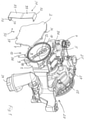
- FIG 1 shows a pump unit with a gas pump 10 of a first exemplary embodiment and a liquid pump 20 in an isometric view of the gas pump 10.
- the pump unit comprises a housing common to both pumps 10 and 20. Such arrangements of pumps are also referred to as tandem arrangements.
- the common housing comprises a housing part 1, which movably supports movable components of the pump unit, in particular a delivery device of gas pump 10 and a delivery device of liquid pump 20, and housing parts 2 and 27, of which housing part 2 is a cover of gas pump 10 and housing part 27 a cover of the liquid pump 20 forms.
- the housing part 1 is formed in one piece, expediently cast in one piece. In principle, however, it can also be composed of several pieces.
- the housing parts 2 and 27 are each formed in one piece from metal and joined to the housing part 1, for example, as shown, each by means of a screw connection.
- the gas pump 10 and the liquid pump 20 are designed as rotary pumps.
- the rotary pumps 10 and 20 are coaxially arranged axially one behind the other along a common axis of rotation.
- the housing part 1 is arranged axially centrally.
- the housing part 2 is arranged on one axial end face and the housing part 27 on the other axial end face of the housing part 1 .
- the delivery device of the gas pump 10 comprises a delivery rotor 11 which can rotate about the axis of rotation and a single vane 12 which is coupled to the delivery rotor 11 in a torque-transmitting manner.
- the conveyor is correspondingly single-leaf.
- the feed rotor 11 guides the wing 12 radially displaceable.
- the housing part 1 forms a housing pot which delimits a delivery chamber 3 on a chamber end face axially facing the liquid pump 20 and surrounds it over the chamber circumference.
- the vane 12 rotates in the delivery chamber 3 and divides the delivery chamber 3 into a delivery cell, which increases on a low-pressure side of the gas pump 10, and another delivery cell, which decreases on a high-pressure side of the gas pump 10. Due to the enlargement of the delivery cell, gas on the low-pressure side is sucked into the enlarging delivery cell through an inlet 4 and is then expelled through an outlet 5 on the high-pressure side when the delivery cell is reduced.
- the gas pump 10 can be operated in particular as a negative pressure or vacuum pump in order to supply a brake booster of a vehicle with negative pressure, for example.
- the brake booster or another unit of the vehicle to be supplied with vacuum is connected to the inlet 4, and the sucked-in gas, preferably air, is expelled via the outlet 5 into the environment, for example into a crankcase of an internal combustion engine.
- a lubricant serving to lubricate the conveyor device 10 is also ejected through the outlet 5 .
- FIG. 1 shows the housing part 2 prior to assembly in a position in which the housing part 2 is axially opposite the facing open end face of the housing part 1 and in order to close the pumping chamber 3 only has to be pressed axially against the housing part 1 and firmly connected to it.
- a sealing surface 6 of the housing part 1 axially facing the housing part 2 and a sealing surface 7 of the housing part 2 axially facing the housing part 1 lie axially against one another and form a sealing joint extending around the delivery chamber 3 in order to seal the delivery chamber 3 over its circumference.
- a groove-shaped sealing recess 9 is formed in the sealing surface 6 around the delivery chamber 3 all the way around.
- the sealing gap between the sealing surfaces 6 and 7 can also be ensured by a sealing liquid located in the sealing recess 9 .
- the sealing recess 9 is filled with the sealing liquid at least during pump operation. An elastic sealing ring or other sealing element is then not required to seal the sealing joint.
- FIG 2 12 shows the pump unit of the first exemplary embodiment in an isometric view of the liquid pump 20.
- the liquid pump 20, like the gas pump 10, is of the vane cell type.
- the liquid pump 20 comprises a multi-vane delivery device with a delivery rotor 21 and 21 rotatable about the axis of rotation common to the gas pump 10 a plurality of vanes 22 distributed over the circumference of the delivery rotor 21.
- the liquid pump 20 can be adjusted with respect to its specific delivery volume. It includes an adjusting ring 23 which is mounted pivotably relative to the housing part 1 in order to be able to adjust an eccentricity of the delivery device 21, 22 and thereby the specific delivery volume of the liquid pump 20.
- a restoring spring 26 exerts a restoring force on the adjusting ring 23 acting in the direction of the maximum delivery volume.
- the adjusting ring 23 is acted upon by the hydraulic fluid delivered by the fluid pump 20 in the direction of a reduction in the specific delivery volume, counteracting this restoring force.
- the vanes 22 divide a delivery chamber of the liquid pump 20 into delivery cells, which enlarge when the delivery device 21, 22 is driven in rotation and the adjusting ring 23 is in an eccentric position relative to the axis of rotation on a low-pressure side of the delivery chamber, whereby liquid is sucked into the delivery chamber, and on a high-pressure side of the pumping chamber decrease again, so that on the high-pressure side the liquid is ejected under increased pressure through an outlet 25 .
- the entire inlet area is denoted by 24 on the low-pressure side of the liquid pump 20 and the entire outlet area is denoted by 25 on the high-pressure side.
- the inlet area comprises an inlet 24 of the housing part 1, which in figure 1 can be seen, and an inlet section 24 located in the housing part 1 upstream of the delivery chamber, in which the return spring 26 is arranged, for example, and from which a chamber inlet leads directly into the delivery chamber.
- the outlet area comprises the chamber outlet leading directly out of the pumping chamber, furthermore an outlet section 25 formed in the housing part 1 and downstream of this an outlet 25 of the housing part 1.
- the liquid pump 20 can in particular be a lubricant pump for supplying a unit with a liquid lubricant.
- the liquid pump 20 is a lubricant pump for supplying liquid lubricant to an internal combustion engine, preferably a drive engine of a vehicle.
- the pump unit is driven in rotation via a drive wheel 13 .
- the pump unit can be driven, for example, by a crankshaft of the internal combustion engine via the drive wheel 13 .
- the drive wheel 13 can be part of a traction drive or a gear drive, in principle also a friction gear.
- the drive wheel 13 is mechanically coupled both to the conveying device 11, 12 and also to the conveying device 21, 22 and can in particular be connected to the two conveying rotors 11 and 21 in a rotationally immovable manner.
- the pump unit can be partially or completely immersed in a sump or other type of reservoir of a liquid, in particular in a reservoir of the liquid that is pumped by the liquid pump 20 .
- the pump unit can be arranged in a lower area, for example on an underside, of an internal combustion engine, partially or completely immersed in the lubricant sump of the internal combustion engine.
- the arrangement in a liquid reservoir, preferably a lubricant reservoir, is advantageous for sealing the gas pump. Due to the negative pressure prevailing in the pumping chamber 3 during pump operation, lubricant can and may be sucked to a certain extent from the environment, the reservoir, via the sealing joint 6, 7 into the sealing recess 9 and from there into the pumping chamber 3.
- the lubricant surrounding the gas pump on the outside which can optionally also serve as a sealing liquid at the same time, effectively prevents ambient air from being sucked in via the sealing gap 6, 7 in the area surrounded by the lubricant, which means that the tightness of the gas pump and thus its efficiency and delivery capacity can be improved .
- figure 3 shows the pump unit of the first embodiment in a longitudinal section.
- the Figures 3 to 5 show the pump unit of the first embodiment in a longitudinal section ( figure 3 ), in a detail ( figure 4 ) and in an axial view of the gas pump 10.
- the housing part 2 is joined to the housing part 1, so that the pumping chamber 3 is tightly closed and the sealing surfaces 6 and 7 together form the sealing joint 8, which surrounds the pumping chamber 3 over its chamber circumference, in that the sealing joint 8 extends around a central longitudinal axis of the delivery chamber 3 .
- the sealing joint 8 is located at an axial end of the pumping chamber 3; in the exemplary embodiment, the sealing surface 6 is an end face on the axial open end of the housing part 2.
- the housing part 2 is planar over its end face facing into the pumping chamber 3, including the sealing surface 7.
- the sealing joint 8 can also be formed, for example, at an axially recessed point, a shoulder surface, of the housing part 1 or, in principle, of the housing part 2 as well.
- the formation of the sealing surface 6 on the axial front end of the housing part 1 in combination with the housing part 2 which is planar at least on its side facing the housing part 1 simplifies production and thus reduces the costs.
- this runs completely, i.e. over 360°.
- the housing part 2 is pressed against the housing part 1 by means of a pressing device 30 so that the sealing surfaces 6 and 7 bear against one another in a sealing manner, forming the sealing joint 8 .
- the pressing device 30 is designed such that it allows a movement of the housing part 2 relative to the housing part 1 in a direction pointing axially away from the housing part 1 when an opening force acting on the housing part 2 in said direction is greater than the pressing force.
- the Opening force can be generated in particular by an overpressure prevailing in the delivery chamber 3 .
- the pressing device 30 can in particular be designed in such a way that the pressing force it exerts ensures adequate sealing via the sealing joint 8 when the pump is at a standstill and in normal pumping operation, but when the pump is started up in the pumping chamber 3 due to the lubricating liquid there due to the pumping movement the conveyor device 11, 12 resulting overpressure causes an expansion movement. Due to such an overpressure, the housing part 2 lifts off the housing part 1 in the area of the sealing joint 8 against the restoring pressing force of the pressing device 30, so that the sealing joint 8 widens to form a relief gap through which excess lubricating fluid in the pumping chamber 3 can escape from the pumping chamber 3 and thus can be displaced by the conveyor 11, 12.
- the inner peripheral contour of the delivery chamber 3 and the vane 11 can be better adapted to one another in order to allow a narrower gap between the inner peripheral contour and the ends of the vane 11 compared to the prior art.
- a reverse turning valve for relief when turning backwards can be dispensed with.
- no ventilation measures have to be taken that would reduce the effective delivery rate in normal pump operation.
- the pressing device 30 is formed as a whole as a spring device. It comprises only a single, uniform spring element 31, which is designed and arranged as a bending stressed spring to generate the pressing force.
- the spring member 31 is a leaf spring. It consists of left and right spring support portions 32 and a spring coupling portion 33 extending from left to right spring support portions 32 . All spring areas 32 and 33 are formed in one piece from spring steel, in the example spring sheet metal.
- the spring support areas 32 and the spring coupling area 33 together form a spring clasp, for example a spring sheet metal clasp, as is basically known for closing preserving jars.
- the spring member 31 spans the housing part 2. With the spring support areas 32, it encompasses an outer circumference of the housing part 2 and a shoulder of the housing part 1 that projects radially outwards. In a central area of the housing part 2, the spring member 31 is coupled to the housing part 2 in order exert the pressing force generated as a spring force on the housing part 2 in this central area.
- the spring member 31 can have several spring arms, for example three or four spring arms, which protrude outwards from a central spring member area in the direction of the sealing joint 8 and in the direction of the housing part 2 in order to distribute the spring force more evenly on the housing part 2 and closer to the sealing joint 8 to raise.
- the spring member 31 has a convex shape in the spring coupling area 33 with respect to the housing part 2 .
- it is a spring plate with a convex profile.
- the coupling portion 33 has the shape of a shallow trough.
- the spring coupling portion 33 may have, for example, an overall convex contour or a shallow "V" shape. In other words, it bulges between the spring support areas 32 in the direction of the housing part 2 . It presses against the housing part 2 with a front area in the direction of the pressing force.
- the spring element 31 is mounted with pretension.
- the spring member 31 bends in its two spring support areas 32 from the spring coupling area 33, each forming an included acute angle. At the free end of the respective spring support area 32, it bends again to form a holding element 34, as best shown in figure 4 is recognizable.
- the spring member 31 forms a flat "U" in each of its spring support regions 32, the short end leg of which forms the retaining element 34.
- With the holding element 34 the spring member 31 engages behind the housing part 1, which has a holding counter-element 35 for the purpose of additional security.
- the retaining elements 34 and counter-retaining elements 35 can each form a latching connection with one another in pairs.
- the kinks can be replaced with softer curves. Strongly curved transitions, however, reduce the installation space required for the pressing device 30, thus enabling a more compact design.
- the sealing element 19 can have a rhombic profile so that it can expand axially over a greater spring deflection during the expansion movement of the housing part 2, but nevertheless does not prevent the liquid to be displaced from escaping through the sealing joint 8.
- the profile of the sealing element 19 can also be circular or square, but it is preferably elongated orthogonally to the sealing surfaces 6 and 7 and can also be oval, for example. This applies to all versions of a gas pump according to the invention with an elastic sealing element such as the sealing element 19.
- the respective sealing element is preferably arranged with the majority of its length measured in the profile in the sealing recess or is secured there by another measure , in order to prevent the respective sealing element from being entrained when the sealing joint 8 is widened by liquid flowing out of the pumping chamber.
- the housing part 2 can move away from the housing part 1 against the restoring pressing force of the spring member 31 to an end position predetermined either by this pressing force or a mechanical stop.
- the spring member 31 can itself form such a mechanical stop for the housing part 2, should the housing part 2 not already increase due to the lifting be held restoring pressing force or moved back towards the housing part 1.
- the spring member 31 can form a mechanical stop, particularly in the area of the transition from the spring coupling area 33 to the respective spring support area 32 .
- the housing part 2 is guided relative to the housing part 1 during the expansion movement. This can be done by the pressing device 30, for example directly by the spring member 31 as in the exemplary embodiment.
- the spring member 31 fulfills the management function by means of its spring support areas 32. The leadership is particularly in the synopsis of Figures 4 and 5 recognizable.
- the housing parts 1 and 2 form lateral guide elements 36 and 37 for the spring support areas 32 by each having a flat recess.
- the spring support areas 32 each engage in a guide engagement in the associated recesses that are located in alignment with one another.
- the guides 36 and 37 sandwich the spring support portions 32 therebetween.
- the guide elements 36 of the housing part 1 hold the spring element 31 in position, and the second housing part 2 is guided axially by the spring element 31 in the area of the side walls of its guide elements 37 .
- the pressing device 30 fulfills the functions of pressing and guiding the housing part 2 and, in an advantageous development, also of a stop to limit the expansion movement of the housing part 2.
- the Figures 6 to 8 show a pump unit with a gas pump 10 of a second embodiment.
- the pump unit differs from the first exemplary embodiment by a modified pressing device 40. Otherwise, it corresponds to the first exemplary embodiment. Apart from the differences described below, reference is therefore made to the statements relating to the first exemplary embodiment.
- the pressing device 40 has only a single spring element 41, which is also shaped and arranged as a spring subjected to bending stress. In contrast to the first exemplary embodiment, however, not only the spring element 41 ensures that the housing part 2 is arranged sufficiently firmly but flexibly for the expansion movement.
- the spring member 41 corresponds with its coupling area 43 to the spring member 31. However, the spring support areas 42 adjoining the spring coupling area 43 on the outside on the left and right are shortened and no longer encompass the housing parts 1 and 2. Rather, the spring member 41 is in its spring support areas 44 by means of the fastening elements 44 supported on the housing part 1 and also attached.
- the spring element 41 corresponds to the spring element 31 with regard to the spring action or generation and application of the pressing force.
- the spring member 41 has a passage for the fastening element 44, which can be formed, for example, as a screw element or press bolt.
- the fastening element 44 protrudes first through the spring member 41 and then through the housing part 2 and projects into a bore of the housing part 1 . It can, for example, be screwed or pressed into the bore.
- the fastening element 44 is surrounded in a shaft area between the sealing surface 6 and the spring support area 42 by a sleeve-shaped guide element 45, which also protrudes into the passage formed in the housing part 2 for the fastening element 44 and has a certain amount of play in the area of the passage to the housing part 2.
- the clearance is dimensioned such that the housing part 2 is guided by the guide element 45 during an expansion movement, but the guide element 45 does not impede the expansion movement.
- the fastening element 44 could also guide the housing part 2 directly in the corresponding shaft area.
- the use of an additional guide element 45 is tribologically advantageous.
- the housing part 2 is held in its assembly position relative to the housing part 1 by the several spaced attachment and guide points, in the exemplary embodiment two attachment and guide points, so that it can only perform the widening movement and correspondingly the closing movement.
- the Figures 9 to 11 show a pump unit with a gas pump 10 and a liquid pump 20 in a third exemplary embodiment, which is derived from the second exemplary embodiment and differs from it only in terms of its pressing device 50, so that the explanation of the pressing device 50 also refers to the second exemplary embodiment and otherwise again reference is made to the first exemplary embodiment, in particular also to the explanations for the pressing device 30 .
- the pressing device 50 has a plurality of separate spring members 51; four spring members 51 were chosen as an example.
- the spring members 51 each have a spring support area 52 and then a spring coupling area 53, with which they each press against the housing part 2 in order to press this in the area of its sealing surface 7 against the sealing surface 6 of the housing part 1, as shown in particular in detail in FIG figure 10 is recognizable.
- the spring members 51 are each supported and fastened in their spring support regions 52 by means of a fastening element 54 on the housing part 1 .
- sleeve-shaped guide elements 55 ensure axial guidance and also positioning of the housing part 2.
- the fastening elements 54 and guide elements 55 correspond at least essentially to the fastening elements 44 and guide elements 45, so that reference is made to the second exemplary embodiment with regard to the support and fastening of the spring members 51 and the guidance of the housing part 2.
- the fastening elements 54 and the passages through which they extend in the spring support areas 52 can be shaped in a manner adapted to one another such that they interact to form an anti-twist device for the respective spring member 51.
- this is also shown as an example for the other spring members 51 only for the lower spring member 51 .
- the Figures 12 to 14 show a pump unit of a fourth exemplary embodiment with a modified pressing device 60.
- a characteristic feature of the fourth exemplary embodiment is that spring members 61 of the pressing device 60 are an integral part of the housing part 2. In this sense, they are integrated spring elements 61.
- the housing part 2 has a central, inherently rigid housing part base structure 2c and the spring members 61 protruding outwards therefrom over a periphery of the housing part base structure 2c.
- the spring members 61 are each formed in the form of a spring arm.
- the spring arms initially protrude a short distance outwards from the housing part base structure 2c.
- Each of the short spring arm sections is followed by a comparatively longer spring arm section, which merges into a spring support area 62 of the respective spring member 61 at an end facing away from the short spring section.
- each of the spring members 61 has a spring coupling section 63 which protrudes freely from the central housing part base structure 2c and extends at least essentially in the circumferential direction over the majority of its length.
- the spring support areas 62 are arranged at the ends of the spring coupling sections 63 .
- the spring members 61 are each fixed immovably relative to the housing part 1.
- the spring members 61 are in the top view of Figures 13 and 14 at least essentially C-shaped, each with an at least essentially L-shaped spring coupling section 63.
- the housing part base structure 2c has the sealing surface 7 on its inner or underside facing the housing part 1 in order to form the sealing groove 8 of the fourth exemplary embodiment with the axially facing sealing surface 6 .
- the sealing groove 8 extends along the periphery of the housing part base structure 2c and in the plan view of FIG figure 13 radially inside the spring members 61.
- the housing part base structure 2c and the spring members 61 are formed in one piece, for example cast from a metallic material and optionally reworked, or preferably stamped from a metal sheet, in particular sheet steel, or formed by means of another separation process.
- the housing part 2 with the integrated spring elements 61 forms a meander spring, the meander arms of which are the spring elements 61 .
- the spring members 61 are springs in the form of meander arms that are subjected to bending stress
- the housing part base structure 2c can be axially prestressed against the sealing surface 6 of the housing part 1 by the spring members 61 .
- the spring members 61 can have a clearance on their underside to the facing end face of the housing part 1 by being there opposite the sealing surface 7 of the housing part 2 ( figure 12 ) are taken back a bit. As a result, the housing part 2 can be fastened to the housing part 1 with pretension.
- an elastic sealing element such as the sealing element 19 ( figure 4 ), renounced.
- the sealing recess 9 is filled with a sealing liquid, at least during pump operation, which can be formed in particular from the lubricating liquid for the gas pump 10 .
- the lubricating liquid can be the liquid delivered by the liquid pump 20 .
- a feed channel 15 can be seen, through which the sealing recess 9 is supplied with the sealing liquid, preferably lubricating liquid.
- the respective sealing recess 9 can be filled with sealing liquid and an elastic sealing element can be dispensed with.
- the liquid seal can also be replaced by arranging an elastic sealing member in the sealing recess 9 in the fourth embodiment.
- sealing by sealing liquid and the supply of the sealing recess 9 with sealing liquid is on the German patent application no. 10 2012 222 753.9 referenced, which is also referred to in this regard.
- gas pump of the fourth exemplary embodiment and also the entire pump unit correspond to those of the first exemplary embodiment.
- the Figures 15 to 17 show a pump unit of a fifth embodiment.
- a gas pump 10 and a liquid pump 20 are combined to form an assembly unit.
- the pump unit corresponds to the previous exemplary embodiments, so that reference is again made to the statements relating to the first exemplary embodiment.
- spring members 71 are each firmly connected to the housing part 1 by means of a fastening element 74 projecting through them. They each have a spring support area 72 on their ends facing away from the housing parts 1 and 2 and a spring coupling area 73 facing the housing part 2, as best shown in FIG figure 16 can be seen. They are each prestressed so that when the pump is at a standstill they exert a prestressing force and, in total, the corresponding pressing force on the housing part 2 .
- the spring elements 71 are distributed along the sealing joint 8 so that, apart from the opening and closing movement, they position and fix the housing part 2 relative to the housing part 1 and, in cooperation, the housing part 2 with the seal for the tight closure of the pumping chamber 3 apply the required pressing force.
- the conveying rotor 11 and also the vane 12 are not secured axially.
- the respective conveying rotor 11 or the respective wing 12 can be secured axially in order to prevent the conveying rotor or the wing from moving axially and causing a rattling noise during an expansion movement of the housing part 2 .
Landscapes
- Engineering & Computer Science (AREA)
- Mechanical Engineering (AREA)
- General Engineering & Computer Science (AREA)
- Physics & Mathematics (AREA)
- Fluid Mechanics (AREA)
- Details And Applications Of Rotary Liquid Pumps (AREA)
- Applications Or Details Of Rotary Compressors (AREA)
Claims (15)
- Pompe à gaz, de préférence pompe à vide, pour alimenter en pression negative un ou plusieurs ensembles, tels qu'un ou plusieurs ensembles d'un véhicule automobile, la pompe à gaz comprenant :(a) une chambre de refoulement (3) comportant une entrée (4) et une sortie (5) pour un gaz ;(b) une première partie de boîtier (1) présentant une première surface d'étanchéité (6) entourant au moins partiellement la chambre de refoulement (3) ;(c) une seconde partie de boîtier (2) qui présente une seconde surface d'étanchéité (7) entourant au moins partiellement la chambre de refoulement (3) et enserre au moins partiellement la chambre de refoulement (3) avec la première partie de boîtier (1) ;(d) un dispositif de refoulement (10) déplaçable dans la chambre de refoulement (3) pour refouler le gaz ;(e) et un dispositif de pressage (30 ; 40 ; 50 ; 60 ; 70) qui presse l'une des parties de boîtier (1, 2) contre l'autre avec une force de pressage, de sorte que les surfaces d'étanchéité (6, 7) reposent l'une contre l'autre et forment ensemble un joint d'étanchéité (8) entourant au moins partiellement la chambre de refoulement (3) pour étancher la chambre de refoulement (3),(f) la seconde partie de boîtier (2) étant déplaçable par rapport à la première partie de boîtier (1) contre la force de pressage afin de pouvoir évaser le joint d'étanchéité (8) pour former une fente de décharge à travers laquelle du liquide situé dans la chambre de refoulement (3) peut s'échapper,caractérisée en ce que(g) une cavité d'étanchéité (9) s'étend autour de la chambre de refoulement (3) dans au moins l'une des surfaces d'étanchéité (6, 7) formant le joint d'étanchéité (8), et(h1) la cavité d'étanchéité (9) est remplie d'un liquide d'étanchéité, de préférence d'un lubrifiant pour la pompe à gaz, au moins lorsque la pompe à gaz est en fonctionnement, afin d'étancher la chambre de refoulement (3) de l'extérieur, de sorte qu'on peut se passer de l'étanchéité au moyen d'une bague d'étanchéité supplémentaire, ou(h2) un élément d'étanchéité (19) est disposé dans la cavité d'étanchéité (9) et comprimé élastiquement lorsque les parties de boîtier (1, 2) sont joints et assure ainsi l'étanchéité nécessaire du joint d'étanchéité (8), l'élément (19) d'étanchéité étant allongé et/ou fixé orthogonalement à la surface d'étanchéité (6, 7) afin d'empêcher l'élément d'étanchéité (19) d'être entraîné par du liquide s'écoulant depuis la chambre de refoulement (3) lorsque le joint d'étanchéité (8) est évasé.
- Pompe à gaz selon la revendication précédente, caractérisée en ce que la fente de décharge court-circuite la chambre de refoulement (3) avec l'environnement de la pompe à gaz ou avec un réservoir pour le liquide.
- Pompe à gaz selon l'une quelconque des revendications précédentes, caractérisée en ce que la pompe à gaz (10) est reliée à un circuit de lubrifiant pour lubrifier au moins un ensemble d'un véhicule, de préférence d'un moteur d'entraînement et/ou d'une transmission du véhicule, et le liquide est le lubrifiant pour lubrifier ledit au moins un ensemble, la pompe à gaz étant de préférence au moins partiellement immergée dans un réservoir de lubrifiant.
- Pompe à gaz selon l'une quelconque des revendications précédentes, caractérisée en ce que l'élément d'étanchéité (19) est en forme de losange ou ovale.
- Pompe à gaz selon au moins l'une des revendications précédentes, caractérisée en ce que le dispositif de pressage (30 ; 40 ; 50 ; 60 ; 70) est flexible élastiquement sur une déflexion de ressort qui est au moins aussi grande qu'une largeur de fente maximale de la fente de décharge.
- Pompe à gaz selon au moins l'une des revendications précédentes, caractérisée en ce que le dispositif de pressage (30 ; 40 ; 50 ; 60 ; 70) comprend un organe de ressort (31 ; 41 ; 51 ; 61 ; 71) qui génère une force de ressort qui forme au moins une partie de la force de pressage et dans des modes de réalisation préférés l'organe de ressort (31 ; 41 ; 51 ; 61 ; 71) est un ressort soumis à une contrainte de flexion (31 ; 41 ; 51 ; 61), tel qu'un ressort à lame, ressort à méandre, ressort à disque ou ressort à membrane, ou un ressort (71) soumis à une contrainte de torsion, tel qu'un ressort hélicoïdal de compression.
- Pompe à gaz selon la revendication précédente, caractérisée en ce que l'organe de ressort (31; 41; 51; 61; 71) est supporté dans une zone de support de ressort (32; 42; 52; 62; 72) et couplé à la seconde partie de boîtier (2) dans une zone de couplage de ressort (33; 43; 53; 63; 73) et agit sur la seconde partie de boîtier (2) de préférence dans la zone de couplage de ressort (33; 43; 53; 63; 73) dans la direction de la force de pressage.
- Pompe à gaz selon la revendication précédente, caractérisée en ce que l'organe de ressort (31 ; 41) est en outre supporté dans une autre zone de support de ressort (32 ; 42), et la zone de couplage de ressort (33 ; 43) s'étend entre les zones de support de ressort (32 ; 42).
- Pompe à gaz selon l'une quelconque des deux revendications précédentes, caractérisée en ce que l'organe de ressort (31 ; 41) est convexe par rapport à la seconde partie de boîtier (2) dans la zone de couplage de ressort (33 ; 43) et agit sur la seconde partie de boîtier (2) avec une force de précontrainte de ressort dans la direction de la force de pressage et presse de préférence contre la seconde partie de boîtier (2).
- Pompe à gaz selon au moins l'une des revendications précédentes et la revendication 5, caractérisée en ce que la seconde partie de boîtier (2) comprend une structure de base de partie de boîtier (2c) présentant la seconde surface d'étanchéité (7), et l'organe de ressort (61) dépasse de la structure de base de partie de boîtier (2c) et est relié de manière fixe à la structure de base de partie de boîtier (2c) et de préférence moulé en une seule pièce avec la structure de base de partie de boîtier (2c).
- Pompe à gaz selon la revendication précédente, caractérisée en ce que le dispositif de pressage comprend un autre organe de ressort (51; 61; 71) pour générer une autre force de ressort, la somme des forces de ressort générées par les organes de ressort (51; 61; 71) formant au moins une partie de la force de pressage, et les organes de ressort (51; 61; 71) étant supportés à des emplacements espacés l'un à l'autre, de préférence sur la première structure de boîtier (1), ou couplés à la seconde structure de boîtier (2) à des emplacements espacés l'un à l'autre sur la seconde structure de boîtier (2), l'autre organe de ressort (61) dépassant de la structure de base de partie de boîtier (2c) et étant relié de manière fixe à la structure de base de partie de boîtier (2c) et de préférence moulé en une seule pièce avec la structure de base de partie de boîtier (2c), dans le cas de la pompe à gaz selon la revendication 10.
- Pompe à gaz selon l'une quelconque des deux revendications précédentes, caractérisée en ce que la seconde partie de boîtier (2) est fixée à la première partie de boîtier (1) au moyen de l'organe de ressort (61) ou de l'autre organe de ressort (61) selon la revendication 11.
- Pompe à gaz selon au moins l'une des revendications précédentes, caractérisée en ce qu'un guidage (32; 45; 55; 75) est prévu qui s'étend dans la direction de mobilité de la seconde partie de boîtier (2), et la seconde partie de boîtier (2) est guidée lors du déplacement le long du guidage (32 ; 45 ; 55 ; 75), l'organe de ressort (31) formant de préférence le guidage (32), de préférence par l'intermédiaire de la zone de support de ressort (32).
- Pompe à gaz selon l'une quelconque des revendications précédentes, caractérisée en ce qu'un mouvement de la seconde partie de boîtier (2) dans une direction qui évase le joint d'étanchéité (8) est limité par une force de ressort s'opposant à l'évasement et augmentant pendant l'évasement ou par une butée fixe (32, 33), l'organe de ressort selon la revendication 6 pouvant former la butée fixe.
- Pompe à gaz selon au moins l'une des revendications précédentes, caractérisée en ce que le dispositif de pressage (30 ; 40 ; 50 ; 60 ; 70) est supporté sur la première partie de boîtier (1) ou sur une autre partie de boîtier facultative de la pompe à gaz (10) ou sur une unité de montage (10, 20) comprenant la pompe à gaz et agit sur la seconde partie de boîtier (2), de sorte que la force de pressage, qui comprend de préférence une force de ressort, est complètement absorbée par les parties de boîtier (1, 2) ou par l'unité de montage (10, 20).
Applications Claiming Priority (2)
| Application Number | Priority Date | Filing Date | Title |
|---|---|---|---|
| DE102013200410.9A DE102013200410B4 (de) | 2013-01-14 | 2013-01-14 | Gaspumpe mit Druckentlastung zur Reduzierung des Anfahrdrehmoments |
| EP14150971.1A EP2754896B1 (fr) | 2013-01-14 | 2014-01-13 | Pompe à gaz avec détente pour la réduction du couple de démarrage |
Related Parent Applications (1)
| Application Number | Title | Priority Date | Filing Date |
|---|---|---|---|
| EP14150971.1A Division EP2754896B1 (fr) | 2013-01-14 | 2014-01-13 | Pompe à gaz avec détente pour la réduction du couple de démarrage |
Publications (2)
| Publication Number | Publication Date |
|---|---|
| EP3421802A1 EP3421802A1 (fr) | 2019-01-02 |
| EP3421802B1 true EP3421802B1 (fr) | 2022-03-02 |
Family
ID=49943213
Family Applications (2)
| Application Number | Title | Priority Date | Filing Date |
|---|---|---|---|
| EP18187866.1A Active EP3421802B1 (fr) | 2013-01-14 | 2014-01-13 | Pompe à gaz avec limiteur de pression pour la réduction du couple de démarrage |
| EP14150971.1A Active EP2754896B1 (fr) | 2013-01-14 | 2014-01-13 | Pompe à gaz avec détente pour la réduction du couple de démarrage |
Family Applications After (1)
| Application Number | Title | Priority Date | Filing Date |
|---|---|---|---|
| EP14150971.1A Active EP2754896B1 (fr) | 2013-01-14 | 2014-01-13 | Pompe à gaz avec détente pour la réduction du couple de démarrage |
Country Status (4)
| Country | Link |
|---|---|
| US (1) | US11506204B2 (fr) |
| EP (2) | EP3421802B1 (fr) |
| CN (1) | CN103925189B (fr) |
| DE (1) | DE102013200410B4 (fr) |
Families Citing this family (9)
| Publication number | Priority date | Publication date | Assignee | Title |
|---|---|---|---|---|
| DE102015105928B4 (de) * | 2015-04-17 | 2018-05-17 | Schwäbische Hüttenwerke Automotive GmbH | Pumpe |
| DE102015109156B4 (de) | 2015-06-10 | 2019-11-07 | Schwäbische Hüttenwerke Automotive GmbH | Pumpe mit Verstelleinrichtung und Steuerventil zur Verstellung des Fördervolumens der Pumpe |
| DE202015105177U1 (de) * | 2015-09-30 | 2017-01-02 | Ebm-Papst St. Georgen Gmbh & Co. Kg | Anordnung zum Bestimmen eines Drucks |
| WO2017175945A1 (fr) * | 2016-04-06 | 2017-10-12 | Lg Electronics Inc. | Compresseur actionné par moteur |
| DE102016122903A1 (de) * | 2016-11-28 | 2018-05-30 | Schwäbische Hüttenwerke Automotive GmbH | Gaspumpe mit Ölrückführung |
| DE102017126750A1 (de) * | 2017-11-14 | 2019-05-16 | Schwäbische Hüttenwerke Automotive GmbH | Pumpvorrichtung |
| WO2019148440A1 (fr) * | 2018-02-02 | 2019-08-08 | 冠翔(香港)工业有限公司 | Compresseur d'air et ensembles associés |
| CN109404283B (zh) * | 2018-11-12 | 2023-10-20 | 江苏梅花机械有限公司 | 一种真空泵油封内侧泄压结构 |
| CN114750976B (zh) * | 2022-06-15 | 2022-11-01 | 成都凯天电子股份有限公司 | 一种直升机自适应供油系统性能地面测试系统及方法 |
Family Cites Families (30)
| Publication number | Priority date | Publication date | Assignee | Title |
|---|---|---|---|---|
| US3193190A (en) * | 1965-07-06 | Lindberg vacuum pump | ||
| US1679620A (en) * | 1926-10-04 | 1928-08-07 | Thomas M Moore | Yielding fastener |
| US2558837A (en) * | 1944-04-13 | 1951-07-03 | Bendix Aviat Corp | Pump |
| US2765745A (en) * | 1955-02-21 | 1956-10-09 | Harry J Sadler | Pump |
| US2997957A (en) * | 1959-03-02 | 1961-08-29 | Entpr Machine And Dev Corp | Motor-driven pump |
| US3041979A (en) * | 1960-06-06 | 1962-07-03 | Jabsco Pump Co | Pump with releasable end cover |
| US3384296A (en) * | 1967-05-19 | 1968-05-21 | Kahane Wilhelm | Sealing of horizontally-split centrifugal compressors |
| US3865515A (en) * | 1973-12-05 | 1975-02-11 | Trw Inc | Self adjusting tangency-clearance compressor with liquid purge capability |
| US4336004A (en) * | 1979-12-26 | 1982-06-22 | The Bendix Corporation | Movable end plate for a vacuum pump |
| GB2092673A (en) * | 1981-02-10 | 1982-08-18 | Denco Agr Ltd | Sliding-vane Rotary Gas Compressors |
| US4516918A (en) * | 1982-05-25 | 1985-05-14 | Trw Inc. | Pump assembly |
| US4497618A (en) * | 1983-09-12 | 1985-02-05 | General Motors Corporation | Combined vacuum pump and power steering pump assembly |
| CN1012003B (zh) * | 1987-04-22 | 1991-03-13 | 瑞典转子机械公司 | 间歇式工作的螺旋压气机 |
| US5239972A (en) * | 1992-03-24 | 1993-08-31 | Nippon Soken, Inc. | Gas/liquid separation device |
| DE4438249A1 (de) * | 1994-10-26 | 1996-05-02 | Bosch Gmbh Robert | Aggregat zum Fördern von Kraftstoff aus einem Vorratstank zu einer Brennkraftmaschine |
| JPH109166A (ja) * | 1996-06-18 | 1998-01-13 | Zexel Corp | ベーン型圧縮機 |
| DE19929631C2 (de) * | 1999-06-29 | 2002-02-07 | Joma Hydromechanic Gmbh | Anordnung einer Öl- und einer Vakuumpumpe an einem Antriebsmotor, insbesondere Brennkraftmaschine |
| EP1613862B1 (fr) * | 2003-04-16 | 2010-11-17 | O.M.P. Officine Mazzocco Pagnoni S.r.l. | Ensemble de pompes a huile et a vide pour un moteur de vehicule automobile |
| DE102004034926B3 (de) | 2004-07-09 | 2005-12-29 | Joma-Hydromechanic Gmbh | Einflügelvakuumpumpe |
| JP4897240B2 (ja) * | 2005-05-25 | 2012-03-14 | カヤバ工業株式会社 | 油圧ポンプ、油圧ポンプユニット、油圧駆動ユニット |
| DE102005031718A1 (de) * | 2005-07-07 | 2007-01-18 | Leybold Vacuum Gmbh | Vakuum-Drehschieberpumpe |
| GB0607198D0 (en) * | 2006-04-10 | 2006-05-17 | Wabco Automotive Uk Ltd | Improved vacuum pump |
| JP4165608B1 (ja) * | 2007-06-26 | 2008-10-15 | 大豊工業株式会社 | ベーン式バキュームポンプ |
| JP2010159740A (ja) * | 2008-12-11 | 2010-07-22 | Toyota Industries Corp | 回転式真空ポンプ |
| US8651843B2 (en) * | 2010-08-04 | 2014-02-18 | GM Global Technology Operations LLC | High efficiency fixed displacement vane pump |
| DE102010044898A1 (de) | 2010-09-09 | 2012-03-15 | Schwäbische Hüttenwerke Automotive GmbH | Vakuumpumpe mit Lüftungseinrichtung |
| JP5653695B2 (ja) * | 2010-09-10 | 2015-01-14 | 三菱重工業株式会社 | ガスケット及び電動圧縮機 |
| US9803637B2 (en) * | 2011-07-14 | 2017-10-31 | Ford Global Technologies, Llc | Variable displacement hydraulic pump control |
| US8961148B2 (en) * | 2011-07-19 | 2015-02-24 | Douglas G. Hunter | Unified variable displacement oil pump and vacuum pump |
| DE102012222753B4 (de) | 2012-12-11 | 2016-08-04 | Schwäbische Hüttenwerke Automotive GmbH | Gaspumpe mit abdichtender Ölnut |
-
2013
- 2013-01-14 DE DE102013200410.9A patent/DE102013200410B4/de active Active
-
2014
- 2014-01-09 US US14/151,129 patent/US11506204B2/en active Active
- 2014-01-13 CN CN201410014323.6A patent/CN103925189B/zh active Active
- 2014-01-13 EP EP18187866.1A patent/EP3421802B1/fr active Active
- 2014-01-13 EP EP14150971.1A patent/EP2754896B1/fr active Active
Also Published As
| Publication number | Publication date |
|---|---|
| US20140199199A1 (en) | 2014-07-17 |
| CN103925189A (zh) | 2014-07-16 |
| CN103925189B (zh) | 2018-01-19 |
| US11506204B2 (en) | 2022-11-22 |
| EP2754896A1 (fr) | 2014-07-16 |
| DE102013200410A1 (de) | 2014-07-17 |
| EP2754896B1 (fr) | 2018-08-22 |
| DE102013200410B4 (de) | 2017-12-07 |
| EP3421802A1 (fr) | 2019-01-02 |
Similar Documents
| Publication | Publication Date | Title |
|---|---|---|
| EP2754896B1 (fr) | Pompe à gaz avec détente pour la réduction du couple de démarrage | |
| DE102011107157B4 (de) | Zahnringpumpe | |
| EP2079923B1 (fr) | Pompe à piston, notamment pompe de carburant haute pression, avec poussoir à galet | |
| EP2743506B1 (fr) | Pompe à gaz dotée d'une rainure à huile d'étanchéification | |
| EP3333381B1 (fr) | Dispositif hydraulique comprenant un élément d'étanchéité | |
| EP3832175A1 (fr) | Joint d'étanchéité de moulure | |
| EP1225337B1 (fr) | Pompe à palettes à déplacement variable | |
| EP2046623B1 (fr) | Systemé comprenant un compresseur et une charge dans un véhicule automobile | |
| EP3077656A1 (fr) | Pompe à carburant | |
| EP3536956B1 (fr) | Sacs de support | |
| DE102012217484A1 (de) | Innenzahnradpumpe, insbesondere für eine hydraulische Fahrzeugbremsanlage | |
| EP1929154B1 (fr) | Pompe a piston | |
| EP2467592B1 (fr) | Pompe de carburant haute pression | |
| EP2286088B1 (fr) | Pompe | |
| DE102007018692A1 (de) | Regelbare Pumpe, insbesondere Flügelzellenpumpe | |
| DE102008017823B4 (de) | Hochdruckpumpe mit einem Pumpenkolben, einem Stößel und einem Rollenschuh bestehend aus wenigstens zwei plattenförmigen Rollenschuhsegmenten | |
| DE102019127388A1 (de) | Fluidversorgung von Unterflügelkammern einer Flügelzellenpumpe | |
| DE102009013986A1 (de) | Verstellbare Rotorpumpe | |
| DE102006034721B4 (de) | Schraubenverdichter mit integrierter Ölpumpe | |
| EP1798415B1 (fr) | Pompe à haute pression | |
| DE102016208763A1 (de) | Pumpe, insbesondere Hochdruckpumpe eines Kraftstoffeinspritzsystems | |
| DE102012211976B3 (de) | Hochdruckpumpe | |
| DE102009028997A1 (de) | Kraftstoffhochdruckpumpe | |
| DE102021119936A1 (de) | Rotationspumpe mit Stellstrukturfeder mit versetzter Wirklinie | |
| DE102011003104A1 (de) | Hochdruckpumpe |
Legal Events
| Date | Code | Title | Description |
|---|---|---|---|
| PUAI | Public reference made under article 153(3) epc to a published international application that has entered the european phase |
Free format text: ORIGINAL CODE: 0009012 |
|
| STAA | Information on the status of an ep patent application or granted ep patent |
Free format text: STATUS: REQUEST FOR EXAMINATION WAS MADE |
|
| 17P | Request for examination filed |
Effective date: 20180807 |
|
| AC | Divisional application: reference to earlier application |
Ref document number: 2754896 Country of ref document: EP Kind code of ref document: P |
|
| AK | Designated contracting states |
Kind code of ref document: A1 Designated state(s): AL AT BE BG CH CY CZ DE DK EE ES FI FR GB GR HR HU IE IS IT LI LT LU LV MC MK MT NL NO PL PT RO RS SE SI SK SM TR |
|
| RIC1 | Information provided on ipc code assigned before grant |
Ipc: F04C 18/34 20060101ALI20210811BHEP Ipc: F04C 15/00 20060101ALI20210811BHEP Ipc: F04C 27/02 20060101ALI20210811BHEP Ipc: F04C 18/344 20060101ALI20210811BHEP Ipc: F04C 28/06 20060101ALI20210811BHEP Ipc: F04C 25/02 20060101ALI20210811BHEP Ipc: F04B 53/16 20060101ALI20210811BHEP Ipc: F04C 28/26 20060101AFI20210811BHEP |
|
| GRAP | Despatch of communication of intention to grant a patent |
Free format text: ORIGINAL CODE: EPIDOSNIGR1 |
|
| STAA | Information on the status of an ep patent application or granted ep patent |
Free format text: STATUS: GRANT OF PATENT IS INTENDED |
|
| INTG | Intention to grant announced |
Effective date: 20210927 |
|
| RAP3 | Party data changed (applicant data changed or rights of an application transferred) |
Owner name: SCHWAEBISCHE HUETTENWERKE AUTOMOTIVE GMBH |
|
| GRAS | Grant fee paid |
Free format text: ORIGINAL CODE: EPIDOSNIGR3 |
|
| GRAA | (expected) grant |
Free format text: ORIGINAL CODE: 0009210 |
|
| STAA | Information on the status of an ep patent application or granted ep patent |
Free format text: STATUS: THE PATENT HAS BEEN GRANTED |
|
| AC | Divisional application: reference to earlier application |
Ref document number: 2754896 Country of ref document: EP Kind code of ref document: P |
|
| AK | Designated contracting states |
Kind code of ref document: B1 Designated state(s): AL AT BE BG CH CY CZ DE DK EE ES FI FR GB GR HR HU IE IS IT LI LT LU LV MC MK MT NL NO PL PT RO RS SE SI SK SM TR |
|
| REG | Reference to a national code |
Ref country code: GB Ref legal event code: FG4D Free format text: NOT ENGLISH |
|
| REG | Reference to a national code |
Ref country code: CH Ref legal event code: EP Ref country code: AT Ref legal event code: REF Ref document number: 1472456 Country of ref document: AT Kind code of ref document: T Effective date: 20220315 |
|
| REG | Reference to a national code |
Ref country code: DE Ref legal event code: R096 Ref document number: 502014016137 Country of ref document: DE |
|
| REG | Reference to a national code |
Ref country code: IE Ref legal event code: FG4D Free format text: LANGUAGE OF EP DOCUMENT: GERMAN |
|
| REG | Reference to a national code |
Ref country code: LT Ref legal event code: MG9D |
|
| REG | Reference to a national code |
Ref country code: NL Ref legal event code: MP Effective date: 20220302 |
|
| PG25 | Lapsed in a contracting state [announced via postgrant information from national office to epo] |
Ref country code: SE Free format text: LAPSE BECAUSE OF FAILURE TO SUBMIT A TRANSLATION OF THE DESCRIPTION OR TO PAY THE FEE WITHIN THE PRESCRIBED TIME-LIMIT Effective date: 20220302 Ref country code: RS Free format text: LAPSE BECAUSE OF FAILURE TO SUBMIT A TRANSLATION OF THE DESCRIPTION OR TO PAY THE FEE WITHIN THE PRESCRIBED TIME-LIMIT Effective date: 20220302 Ref country code: NO Free format text: LAPSE BECAUSE OF FAILURE TO SUBMIT A TRANSLATION OF THE DESCRIPTION OR TO PAY THE FEE WITHIN THE PRESCRIBED TIME-LIMIT Effective date: 20220602 Ref country code: LT Free format text: LAPSE BECAUSE OF FAILURE TO SUBMIT A TRANSLATION OF THE DESCRIPTION OR TO PAY THE FEE WITHIN THE PRESCRIBED TIME-LIMIT Effective date: 20220302 Ref country code: HR Free format text: LAPSE BECAUSE OF FAILURE TO SUBMIT A TRANSLATION OF THE DESCRIPTION OR TO PAY THE FEE WITHIN THE PRESCRIBED TIME-LIMIT Effective date: 20220302 Ref country code: ES Free format text: LAPSE BECAUSE OF FAILURE TO SUBMIT A TRANSLATION OF THE DESCRIPTION OR TO PAY THE FEE WITHIN THE PRESCRIBED TIME-LIMIT Effective date: 20220302 Ref country code: BG Free format text: LAPSE BECAUSE OF FAILURE TO SUBMIT A TRANSLATION OF THE DESCRIPTION OR TO PAY THE FEE WITHIN THE PRESCRIBED TIME-LIMIT Effective date: 20220602 |
|
| PG25 | Lapsed in a contracting state [announced via postgrant information from national office to epo] |
Ref country code: PL Free format text: LAPSE BECAUSE OF FAILURE TO SUBMIT A TRANSLATION OF THE DESCRIPTION OR TO PAY THE FEE WITHIN THE PRESCRIBED TIME-LIMIT Effective date: 20220302 Ref country code: LV Free format text: LAPSE BECAUSE OF FAILURE TO SUBMIT A TRANSLATION OF THE DESCRIPTION OR TO PAY THE FEE WITHIN THE PRESCRIBED TIME-LIMIT Effective date: 20220302 Ref country code: GR Free format text: LAPSE BECAUSE OF FAILURE TO SUBMIT A TRANSLATION OF THE DESCRIPTION OR TO PAY THE FEE WITHIN THE PRESCRIBED TIME-LIMIT Effective date: 20220603 Ref country code: FI Free format text: LAPSE BECAUSE OF FAILURE TO SUBMIT A TRANSLATION OF THE DESCRIPTION OR TO PAY THE FEE WITHIN THE PRESCRIBED TIME-LIMIT Effective date: 20220302 |
|
| PG25 | Lapsed in a contracting state [announced via postgrant information from national office to epo] |
Ref country code: NL Free format text: LAPSE BECAUSE OF FAILURE TO SUBMIT A TRANSLATION OF THE DESCRIPTION OR TO PAY THE FEE WITHIN THE PRESCRIBED TIME-LIMIT Effective date: 20220302 |
|
| PG25 | Lapsed in a contracting state [announced via postgrant information from national office to epo] |
Ref country code: SM Free format text: LAPSE BECAUSE OF FAILURE TO SUBMIT A TRANSLATION OF THE DESCRIPTION OR TO PAY THE FEE WITHIN THE PRESCRIBED TIME-LIMIT Effective date: 20220302 Ref country code: SK Free format text: LAPSE BECAUSE OF FAILURE TO SUBMIT A TRANSLATION OF THE DESCRIPTION OR TO PAY THE FEE WITHIN THE PRESCRIBED TIME-LIMIT Effective date: 20220302 Ref country code: RO Free format text: LAPSE BECAUSE OF FAILURE TO SUBMIT A TRANSLATION OF THE DESCRIPTION OR TO PAY THE FEE WITHIN THE PRESCRIBED TIME-LIMIT Effective date: 20220302 Ref country code: PT Free format text: LAPSE BECAUSE OF FAILURE TO SUBMIT A TRANSLATION OF THE DESCRIPTION OR TO PAY THE FEE WITHIN THE PRESCRIBED TIME-LIMIT Effective date: 20220704 Ref country code: EE Free format text: LAPSE BECAUSE OF FAILURE TO SUBMIT A TRANSLATION OF THE DESCRIPTION OR TO PAY THE FEE WITHIN THE PRESCRIBED TIME-LIMIT Effective date: 20220302 Ref country code: CZ Free format text: LAPSE BECAUSE OF FAILURE TO SUBMIT A TRANSLATION OF THE DESCRIPTION OR TO PAY THE FEE WITHIN THE PRESCRIBED TIME-LIMIT Effective date: 20220302 |
|
| PG25 | Lapsed in a contracting state [announced via postgrant information from national office to epo] |
Ref country code: IS Free format text: LAPSE BECAUSE OF FAILURE TO SUBMIT A TRANSLATION OF THE DESCRIPTION OR TO PAY THE FEE WITHIN THE PRESCRIBED TIME-LIMIT Effective date: 20220702 Ref country code: AL Free format text: LAPSE BECAUSE OF FAILURE TO SUBMIT A TRANSLATION OF THE DESCRIPTION OR TO PAY THE FEE WITHIN THE PRESCRIBED TIME-LIMIT Effective date: 20220302 |
|
| REG | Reference to a national code |
Ref country code: DE Ref legal event code: R097 Ref document number: 502014016137 Country of ref document: DE |
|
| PLBE | No opposition filed within time limit |
Free format text: ORIGINAL CODE: 0009261 |
|
| STAA | Information on the status of an ep patent application or granted ep patent |
Free format text: STATUS: NO OPPOSITION FILED WITHIN TIME LIMIT |
|
| PG25 | Lapsed in a contracting state [announced via postgrant information from national office to epo] |
Ref country code: DK Free format text: LAPSE BECAUSE OF FAILURE TO SUBMIT A TRANSLATION OF THE DESCRIPTION OR TO PAY THE FEE WITHIN THE PRESCRIBED TIME-LIMIT Effective date: 20220302 |
|
| 26N | No opposition filed |
Effective date: 20221205 |
|
| PG25 | Lapsed in a contracting state [announced via postgrant information from national office to epo] |
Ref country code: SI Free format text: LAPSE BECAUSE OF FAILURE TO SUBMIT A TRANSLATION OF THE DESCRIPTION OR TO PAY THE FEE WITHIN THE PRESCRIBED TIME-LIMIT Effective date: 20220302 |
|
| REG | Reference to a national code |
Ref country code: DE Ref legal event code: R119 Ref document number: 502014016137 Country of ref document: DE |
|
| REG | Reference to a national code |
Ref country code: CH Ref legal event code: PL |
|
| GBPC | Gb: european patent ceased through non-payment of renewal fee |
Effective date: 20230113 |
|
| PG25 | Lapsed in a contracting state [announced via postgrant information from national office to epo] |
Ref country code: LU Free format text: LAPSE BECAUSE OF NON-PAYMENT OF DUE FEES Effective date: 20230113 |
|
| REG | Reference to a national code |
Ref country code: BE Ref legal event code: MM Effective date: 20230131 |
|
| PG25 | Lapsed in a contracting state [announced via postgrant information from national office to epo] |
Ref country code: LI Free format text: LAPSE BECAUSE OF NON-PAYMENT OF DUE FEES Effective date: 20230131 Ref country code: GB Free format text: LAPSE BECAUSE OF NON-PAYMENT OF DUE FEES Effective date: 20230113 Ref country code: DE Free format text: LAPSE BECAUSE OF NON-PAYMENT OF DUE FEES Effective date: 20230801 Ref country code: CH Free format text: LAPSE BECAUSE OF NON-PAYMENT OF DUE FEES Effective date: 20230131 |
|
| PG25 | Lapsed in a contracting state [announced via postgrant information from national office to epo] |
Ref country code: FR Free format text: LAPSE BECAUSE OF NON-PAYMENT OF DUE FEES Effective date: 20230131 Ref country code: BE Free format text: LAPSE BECAUSE OF NON-PAYMENT OF DUE FEES Effective date: 20230131 |
|
| PG25 | Lapsed in a contracting state [announced via postgrant information from national office to epo] |
Ref country code: IT Free format text: LAPSE BECAUSE OF NON-PAYMENT OF DUE FEES Effective date: 20230113 Ref country code: IE Free format text: LAPSE BECAUSE OF NON-PAYMENT OF DUE FEES Effective date: 20230113 |
|
| REG | Reference to a national code |
Ref country code: AT Ref legal event code: MM01 Ref document number: 1472456 Country of ref document: AT Kind code of ref document: T Effective date: 20230113 |
|
| PG25 | Lapsed in a contracting state [announced via postgrant information from national office to epo] |
Ref country code: AT Free format text: LAPSE BECAUSE OF NON-PAYMENT OF DUE FEES Effective date: 20230113 |
|
| PG25 | Lapsed in a contracting state [announced via postgrant information from national office to epo] |
Ref country code: AT Free format text: LAPSE BECAUSE OF NON-PAYMENT OF DUE FEES Effective date: 20230113 |
|
| PG25 | Lapsed in a contracting state [announced via postgrant information from national office to epo] |
Ref country code: MC Free format text: LAPSE BECAUSE OF FAILURE TO SUBMIT A TRANSLATION OF THE DESCRIPTION OR TO PAY THE FEE WITHIN THE PRESCRIBED TIME-LIMIT Effective date: 20220302 |
|
| PG25 | Lapsed in a contracting state [announced via postgrant information from national office to epo] |
Ref country code: MC Free format text: LAPSE BECAUSE OF FAILURE TO SUBMIT A TRANSLATION OF THE DESCRIPTION OR TO PAY THE FEE WITHIN THE PRESCRIBED TIME-LIMIT Effective date: 20220302 |
|
| PG25 | Lapsed in a contracting state [announced via postgrant information from national office to epo] |
Ref country code: CY Free format text: LAPSE BECAUSE OF FAILURE TO SUBMIT A TRANSLATION OF THE DESCRIPTION OR TO PAY THE FEE WITHIN THE PRESCRIBED TIME-LIMIT; INVALID AB INITIO Effective date: 20140113 |
|
| PG25 | Lapsed in a contracting state [announced via postgrant information from national office to epo] |
Ref country code: HU Free format text: LAPSE BECAUSE OF FAILURE TO SUBMIT A TRANSLATION OF THE DESCRIPTION OR TO PAY THE FEE WITHIN THE PRESCRIBED TIME-LIMIT; INVALID AB INITIO Effective date: 20140113 |