EP2047227B1 - Verfahren zur analyse von reifenvibrationseigenschaften und vorrichtung zum ausführen des verfahrens - Google Patents
Verfahren zur analyse von reifenvibrationseigenschaften und vorrichtung zum ausführen des verfahrens Download PDFInfo
- Publication number
- EP2047227B1 EP2047227B1 EP07787937A EP07787937A EP2047227B1 EP 2047227 B1 EP2047227 B1 EP 2047227B1 EP 07787937 A EP07787937 A EP 07787937A EP 07787937 A EP07787937 A EP 07787937A EP 2047227 B1 EP2047227 B1 EP 2047227B1
- Authority
- EP
- European Patent Office
- Prior art keywords
- wheel
- tire
- vibrations
- actuator
- frame
- Prior art date
- Legal status (The legal status is an assumption and is not a legal conclusion. Google has not performed a legal analysis and makes no representation as to the accuracy of the status listed.)
- Not-in-force
Links
- 238000000034 method Methods 0.000 title claims abstract description 18
- 230000005284 excitation Effects 0.000 claims description 14
- 238000012546 transfer Methods 0.000 claims description 11
- 230000005520 electrodynamics Effects 0.000 claims description 6
- 230000001066 destructive effect Effects 0.000 claims description 5
- XAGFODPZIPBFFR-UHFFFAOYSA-N aluminium Chemical compound [Al] XAGFODPZIPBFFR-UHFFFAOYSA-N 0.000 claims description 4
- 229910052782 aluminium Inorganic materials 0.000 claims description 4
- 239000004411 aluminium Substances 0.000 claims description 4
- 230000005484 gravity Effects 0.000 claims description 2
- 238000011161 development Methods 0.000 description 5
- 230000018109 developmental process Effects 0.000 description 5
- 238000005452 bending Methods 0.000 description 4
- 230000000694 effects Effects 0.000 description 4
- 238000012360 testing method Methods 0.000 description 4
- 230000001133 acceleration Effects 0.000 description 3
- 238000010276 construction Methods 0.000 description 3
- 238000005259 measurement Methods 0.000 description 3
- 230000001419 dependent effect Effects 0.000 description 2
- 238000013461 design Methods 0.000 description 2
- 230000010355 oscillation Effects 0.000 description 2
- 230000003595 spectral effect Effects 0.000 description 2
- 238000001228 spectrum Methods 0.000 description 2
- 239000000725 suspension Substances 0.000 description 2
- DOSMHBDKKKMIEF-UHFFFAOYSA-N 2-[3-(diethylamino)-6-diethylazaniumylidenexanthen-9-yl]-5-[3-[3-[4-(1-methylindol-3-yl)-2,5-dioxopyrrol-3-yl]indol-1-yl]propylsulfamoyl]benzenesulfonate Chemical compound C1=CC(=[N+](CC)CC)C=C2OC3=CC(N(CC)CC)=CC=C3C(C=3C(=CC(=CC=3)S(=O)(=O)NCCCN3C4=CC=CC=C4C(C=4C(NC(=O)C=4C=4C5=CC=CC=C5N(C)C=4)=O)=C3)S([O-])(=O)=O)=C21 DOSMHBDKKKMIEF-UHFFFAOYSA-N 0.000 description 1
- 230000002238 attenuated effect Effects 0.000 description 1
- 239000000463 material Substances 0.000 description 1
- 230000001131 transforming effect Effects 0.000 description 1
Images


Classifications
-
- G—PHYSICS
- G01—MEASURING; TESTING
- G01M—TESTING STATIC OR DYNAMIC BALANCE OF MACHINES OR STRUCTURES; TESTING OF STRUCTURES OR APPARATUS, NOT OTHERWISE PROVIDED FOR
- G01M17/00—Testing of vehicles
- G01M17/007—Wheeled or endless-tracked vehicles
- G01M17/02—Tyres
- G01M17/025—Tyres using infrasonic, sonic or ultrasonic vibrations
Definitions
- the invention relates to a method for analysing tire vibration characteristics and an apparatus for carrying out said method.
- the tyre is the element through which the road and the vehicle exchange forces. If the structure of the tire is rigid, forces are transmitted directly, without any attenuation. If the structure is elastic the forces transmitted can be attenuated, or on the other hand amplified, due to resonances.
- the tire is a viscoelastic body and, like all viscoelastic bodies, it vibrates when it is excited (by forces or by deformations). It is therefore possible to say that the vibrations felt by the passengers inside the vehicle are influenced or generated by the tire.
- testing benches comprising a wheel support for supporting a wheel with a tire to be analysed the excitation of vibrations is made via the tire surface. In this case a superposition of free tire vibrations with friction effects cannot be excluded.
- EP-B1 0 775 902 and 0 775 904 disclose a torsional vibrator capable of torsionally exciting a tire of a wheel and providing measurements of angular vibrations.
- the wheel with the tire fitted thereon is fastened on a driving shaft of the vibrator.
- Two acceleration transducers are fastened to the rim in a diametrically opposite position.
- Two further acceleration transducers are fastened to the tire by means of a clamp fastened to the tire surface.
- the driving shaft performs angular oscillations and torsionally excites the wheel that thus vibrates in a rotational direction.
- the accelerometers detect rotational vibrations and provide measurements of angular acceleration of the wheel and of the tire.
- This known apparatus only permits analysis in one functional direction i.e. rotational vibrations.
- the object of the present invention is a method for non-destructive analysis of natural vibrations of tires and an apparatus for carrying out said method that allows separate analysis of the natural vibrations in all four functional directions i.e. longitudinal vibrations, lateral vibrations, radial vibrations and rotational vibrations.
- the influencing variables of the natural vibrations of the tire are separated. This is achieved by supporting the wheel and the tire fitted thereon such that the motion is guided in one predefined direction of interest. Since excitation is made via the wheel, no superposition due to friction effects or modulation due to bending stress occurs.
- said method is carried out with and without load on said tire.
- said excitation is introduced in the center of gravity of said wheel.
- said output signal y(t) is formed by the vibration of the complete tire structure of the tire surface.
- the apparatus according to the invention analysis of the natural vibrations in all four functional directions i.e. longitudinal vibrations, lateral vibrations, radial vibrations and rotational vibrations can be carried out. Superposition effected by friction effects and modulation effected by local bending stress is avoided since excitation is made via the wheel on which the tire is fitted. Furthermore, the influencing variables of the natural vibrations of the tire are separated since the frame is flexibly supported in one predefined direction by elastic means.
- the apparatus according to the invention provides a modular design. Thus, the apparatus can be used for the analysis of a broad range of tires, by adapting the apparatus to the size of the tire.
- said elastic means is comprised of a plurality of leaf springs distanced apart from each other.
- the stiffness of said leaf springs is dimensioned such that the frequency of resonance in the direction of excitation lies below the desired frequency of excitation of said tire.
- the stiffness of said frame and of said leaf springs in the transverse direction is dimensioned such that the frequency of resonance is above the desired frequency of excitation of said tire.
- said frame consists of welded aluminium wrought products.
- said wheel support comprises two supporting members distanced apart from each other, said supporting members supporting a shaft for mounting said wheel.
- a wheel adaptor is connected with said shaft.
- said shaft is supported in clamping jaws arranged at the end of said shaft.
- said wheel support comprises at least one thrust member for taking up thrust forces.
- Said actuator advantageously can be a hydraulic, electrodynamic, electromagnetic or a piezoelectric actuator.
- said actuator is an electrodynamic shaker comprising a stinger connected with said frame.
- said actuator for introducing rotational vibrations is comprised of at least one shaker which is connected with a lever fastened to said shaft.
- said actuator is elastically suspended.
- the frame 11 supports the wheel support 16 supporting a wheel 15 with a tire 14 to be analysed.
- the stiff frame 11 is connected with a base part 12 by elastic means which is embodied as a plurality of leaf springs 13a, 13b distanced apart from each other.
- the leaf springs 13a, 13b are only arranged at the portions 11a, 11b of the frame 11.
- the frame 11 is flexibly supported in the predefined functional direction (radial direction) indicated by arrow 29.
- the frame 11 is not flexible in a lateral direction indicated by arrow 30.
- Fig. 4 shows a separate leaf spring 13 as used in the apparatus 10 according to Fig. 1 .
- the leaf spring 13 has a rectangular shape and is connected by means of clamping plates 24 with the frame 11 and the base plate 12 as shown in Fig. 5 .
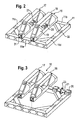
- Fig. 2 and 3 show the detailed construction of the wheel support 16.
- the wheel support 16 comprises two supporting members 17, 18 which are distanced apart from each other.
- the two supporting members 17, 18 consist of welded aluminium wrought products.
- the support members 17, 18 comprise thrust members 19 of essentially triangular shape for taking up thrust forces.
- the support members 17, 18 are fastened to the frame 11 by means of a plurality of screws 31 which are fastened into holes 32 provided in the frame 11. Such holes 32 are provided at all portions 11a, 11b, 11c and 11d of the frame 11. Thus, the wheel support 16 can be turned by 90 degrees from the shown position. By turning the wheel support 16, analysis of the natural vibrations can be carried out in the lateral direction. Stiffening struts 33a, 33b fastened to both of the supporting members 17, 18 are provided in order to stabilize the construction.
- the base plate 12 can be connected to the ground by means of an angle bracket 25.
- the supporting members 17, 18 support a shaft 21 comprising a wheel adaptor 23 for fastening the wheel 15.
- Fig. 3 shows that the shaft 21 is supported in clamping jaws 20 arranged at the ends of the shaft 21.
- the clamping jaws 20 are fastened to the support members 17, 18. In the closed position the clamping jaws 20 do not permit any rotation of the shaft 21.
- an electrodynamic shaker 26 comprising a stinger 27 is arranged next to the apparatus 10.
- the stinger 27 is connected with the frame 11 such that vibrations excerted from the shaker 26 are transferred to the frame 11 and the wheel 15.
- the shaker 26 is elastically suspended by means of elastic suspensions 28. Such a shaker 26 is used for measurements of radial and lateral vibrations.
- the apparatus 10 permits the analysis of natural vibrations of tires in the radial direction indicated by arrow 29 of Fig. 1 .
- the electrodynamic shaker 26 of Fig. 6 is arranged at the portions 11a or 11b of the frame 11, which is not shown in Fig. 1 .
- the stinger 27 connected with the frame 11 excites vibrations in the wheel 15.
- an input signal x(t) is measured at a contact surface between the tire 14 and the wheel 15.
- the output signal y(t) is measured by means of further accelerometers at the surface of the tire 14.
- This transfer function H(f) characterizes the natural vibrations of the tire.
- the transfer function of the tire H tire can be determined in another manner if an increased signal quality is desired.
- the wheel support 16 can be turned by 90 degrees and fixed to the holes 32 provided in the frame 11.
- the apparatus 20 provides a modular design.
- the apparatus 10 can be used for the analysis of a broad range of tires.
- the influencing variables of the natural vibrations of the tire are separated since the frame 11 is flexibly supported in one predefined direction by a plurality of leaf springs 13a, 13b. Since excitation of vibrations is made via the wheel, no superposition with friction effects or modulation due to bending stress will occur.
Landscapes
- Physics & Mathematics (AREA)
- General Physics & Mathematics (AREA)
- Testing Of Balance (AREA)
Claims (17)
- Verfahren zur zerstörungsfreien Analyse natürlicher Vibrationen von Reifen, umfassend die folgenden Schritte:- Befestigung eines zu analysierenden Reifens (14) auf einer Felge (15);- Einrichten der Felge (15) in einer Vorrichtung (10), die einen die Felge (15) stützenden Felgenträger (16) aufweist, wobei der Felgenträger (16) verstellbar an einem steifen Rahmen (11) befestigt ist, der flexibel durch elastische Mittel (13a, 13b) mit einem Basisteil (12) verbunden ist, so dass eine separate Analyse der natürlichen Vibrationen in einer vorher bestimmten funktionalen Richtung ermöglicht wird;- Anregung von Vibrationen in der vorherbestimmten funktionalen Richtung in der Felge (15) durch einen Aktor (26);- Messung eines Eingangssignals x(t) an einer Kontaktoberfläche zwischen dem Reifen (14) und der Felge (15);- Messung eines Ausgangssignals y(t) an einer Oberfläche des Reifens (14);- Berechnung einer Übertragungsfunktion des Reifens HReifen mittels des Eingangssignals x(t) und des Ausgangssignals y(t).
- Verfahren nach Anspruch 1, dadurch gekennzeichnet, dass die Analyse mit und ohne Last auf dem Reifen (14) ausgeführt wird.
- Verfahren nach Anspruch 1 oder 2, dadurch gekennzeichnet, dass die Anregung im Körperschwerpunkt der Felge (15) eingebracht wird.
- Verfahren nach einem der Ansprüche 1 bis 3, dadurch gekennzeichnet, dass das Ausgangssignal y(t) durch die Vibration der vollständigen Reifenstruktur an der Oberfläche des Reifens erzeugt wird.
- Vorrichtung (10) zum Ausführen des Verfahrens nach einem der Ansprüche 1 bis 4, umfassend- Einen Felgenträger (16) zum Stützen einer Felge (15) mit einem zu analysierenden Reifen (14);- Der Felgenträger (16) ist verstellbar an einem steifen Rahmen (11) befestigt;- Ein Basisteil (12) ist durch elastische Mittel (13a, 13b) flexibel mit dem steifen Rahmen (11) verbunden;- Die elastischen Mittel (13a, 13b) sind derart ausgestaltet, dass der steife Rahmen (11) in einer vorherbestimmten funktionalen Richtung flexibel gestützt ist; und- Ein Aktor (26) zum Anregen von Vibrationen in der vorherbestimmten funktionalen Richtung in der Felge (15).
- Vorrichtung (10) nach Anspruch 5, dadurch gekennzeichnet, dass die elastischen Mittel (13a, 13b) eine Vielzahl an voneinander beabstandeten Blattfedern umfassen.
- Vorrichtung (10) nach Anspruch 5 oder 6, dadurch gekennzeichnet, dass die Steifigkeit der Blattfedern (13a, 13b) derart dimensioniert ist, dass die Eigenfrequenz in Richtung der Anregung unterhalb der gewünschten Anregungsfrequenz des Reifen (14) liegt.
- Vorrichtung (10) nach einem der Ansprüche 5 bis 7, dadurch gekennzeichnet, dass die Steifigkeit des steifen Rahmens (11) und der Blattfedern (13a, 13b) in Querrichtung derart dimensioniert ist, dass die Eigenfrequenz über der gewünschten Anregungsfrequenz des Reifens (14) ist.
- Vorrichtung (10) nach einem der Ansprüche 5 bis 8, dadurch gekennzeichnet, dass der steife Rahmen (11) aus geschweißten, bearbeiteten Aluminiumerzeugnissen besteht.
- Vorrichtung (10) nach einem der Ansprüche 5 bis 9, dadurch gekennzeichnet, dass der Felgenträger (16) zwei voneinander beabstandete Trägerelemente (17, 18) umfasst, wobei die Trägerelemente (17, 18) eine Welle (21) zur Befestigung der Felge (15) stützen.
- Vorrichtung (10) nach Anspruch 10, dadurch gekennzeichnet, dass ein Felgenadapter (23) mit der Welle (21) verbunden ist.
- Vorrichtung (10) nach Anspruch 10 oder 11, dadurch gekennzeichnet, dass die Welle (21) in Klemmbacken (20) gestützt ist, die an den Enden der Welle (21) angeordnet sind.
- Vorrichtung (10) nach einem der Ansprüche 5 bis 12, dadurch gekennzeichnet, dass der Felgenträger (16) wenigstens ein Schubelement (19) zur Aufnahme von Schubkräften aufweist.
- Vorrichtung (10) nach einem der Ansprüche 5 bis 13, dadurch gekennzeichnet, dass der Aktor (26) ein hydraulischer, elektrodynamischer, elektromagnetischer oder piezoelektrischer Aktor ist.
- Vorrichtung (10) nach einem der Ansprüche 5 bis 14, dadurch gekennzeichnet, dass der Aktor (26) ein elektrodynamischer Rüttler ist, der eine mit dem Rahmen verbundene Vorschubstange aufweist.
- Vorrichtung (10) nach einem der Ansprüche 5 bis 15, dadurch gekennzeichnet, dass der Aktor (26) zum Einbringen von Drehschwingungen wenigstens einen Rüttler aufweist, der mit einem mit der Welle (21) verbundenen Hebel befestigt ist.
- Vorrichtung (10) nach einem der Ansprüche 5 bis 16, dadurch gekennzeichnet, dass der Aktor (26) elastisch abgefedert ist.
Priority Applications (1)
| Application Number | Priority Date | Filing Date | Title |
|---|---|---|---|
| EP07787937A EP2047227B1 (de) | 2006-07-27 | 2007-07-26 | Verfahren zur analyse von reifenvibrationseigenschaften und vorrichtung zum ausführen des verfahrens |
Applications Claiming Priority (3)
| Application Number | Priority Date | Filing Date | Title |
|---|---|---|---|
| EP06118017 | 2006-07-27 | ||
| PCT/EP2007/057714 WO2008012345A1 (en) | 2006-07-27 | 2007-07-26 | Method for analysing tire vibration characteristics and an apparatus for carrying out said method |
| EP07787937A EP2047227B1 (de) | 2006-07-27 | 2007-07-26 | Verfahren zur analyse von reifenvibrationseigenschaften und vorrichtung zum ausführen des verfahrens |
Publications (2)
| Publication Number | Publication Date |
|---|---|
| EP2047227A1 EP2047227A1 (de) | 2009-04-15 |
| EP2047227B1 true EP2047227B1 (de) | 2011-01-05 |
Family
ID=37440787
Family Applications (1)
| Application Number | Title | Priority Date | Filing Date |
|---|---|---|---|
| EP07787937A Not-in-force EP2047227B1 (de) | 2006-07-27 | 2007-07-26 | Verfahren zur analyse von reifenvibrationseigenschaften und vorrichtung zum ausführen des verfahrens |
Country Status (5)
| Country | Link |
|---|---|
| US (1) | US8024965B2 (de) |
| EP (1) | EP2047227B1 (de) |
| AT (1) | ATE494535T1 (de) |
| DE (1) | DE602007011767D1 (de) |
| WO (1) | WO2008012345A1 (de) |
Families Citing this family (9)
| Publication number | Priority date | Publication date | Assignee | Title |
|---|---|---|---|---|
| NL1028222C2 (nl) * | 2005-02-08 | 2006-08-09 | Petrus Johannes Gerardu Linden | Zelfondersteunende en zelfuitlijnende trillingsexcitator. |
| US8977422B1 (en) | 2013-11-06 | 2015-03-10 | The Goodyear Tire & Rubber Company | Accoustic/vibration sensor and tire assembly and method of construction thereof |
| US9354137B2 (en) * | 2014-01-28 | 2016-05-31 | GM Global Technology Operations LLC | Systems and methods for determining oscillations of a tire |
| RU2672529C1 (ru) * | 2017-12-18 | 2018-11-15 | Российская Федерация, от имени которой выступает Государственная корпорация по атомной энергии "Росатом" (Госкорпорация "Росатом") | Способ формирования спектров случайной вибрации |
| US10969292B2 (en) | 2019-08-30 | 2021-04-06 | Balanced Engineering Solution, Llc | Apparatus for measuring imbalance forces of a tire/hub assembly of a vehicle during motion of the vehicle |
| JP7555252B2 (ja) * | 2020-12-04 | 2024-09-24 | Toyo Tire株式会社 | タイヤ放射音の評価方法 |
| US11480491B1 (en) * | 2022-02-14 | 2022-10-25 | Balanced Engineering Solution, Llc | Method for determining vibrational anomalies of a vehicle |
| US11656156B1 (en) | 2022-09-26 | 2023-05-23 | Balanced Engineering Solution, Llc | Axle-mounted sensor cuff apparatus for determining anomalies associated with a railcar wheelset, or a railcar bogie assembly that the railcar wheelset is part of, or a track |
| US11731673B1 (en) | 2022-09-26 | 2023-08-22 | Balanced Engineering Solution, Llc | Wheel-mounted sensor ring apparatus for determining anomalies associated with a railcar wheelset, or a railcar bogie assembly that the railcar wheelset is part of, or a track |
Family Cites Families (9)
| Publication number | Priority date | Publication date | Assignee | Title |
|---|---|---|---|---|
| US2378237A (en) * | 1942-09-02 | 1945-06-12 | Wingfoot Corp | Method and apparatus for ultrasonic testing |
| US3604249A (en) * | 1968-06-21 | 1971-09-14 | Massachusetts Inst Technology | Method and apparatus for testing pneumatic tire casings |
| US3871210A (en) * | 1971-11-12 | 1975-03-18 | Hofmann Maschf Geb | Vibration testing apparatus with preload control |
| DE2244630B2 (de) * | 1972-09-12 | 1975-09-25 | Volkswagenwerk Ag, 3180 Wolfsburg | Umlaufbiege-Prüfvorrichtung |
| US3815407A (en) * | 1973-01-22 | 1974-06-11 | Department Of Transportation | Resonance tire inspection method and apparatus |
| IT1279060B1 (it) | 1995-11-21 | 1997-12-04 | Pirelli | Metodo di controllo per determinare il grado di comfort di un pneumatico di una ruota per veicolo |
| IT1279061B1 (it) | 1995-11-21 | 1997-12-04 | Pirelli | Vibratore torsionale |
| US6381547B1 (en) * | 2000-06-12 | 2002-04-30 | Foster-Miller, Inc. | Tire defect detection system and method |
| KR20030043366A (ko) | 2001-11-28 | 2003-06-02 | 금호산업주식회사 | 타이어 고유진동모드 및 진동전달특성 측정 장치 |
-
2007
- 2007-07-26 AT AT07787937T patent/ATE494535T1/de not_active IP Right Cessation
- 2007-07-26 WO PCT/EP2007/057714 patent/WO2008012345A1/en not_active Ceased
- 2007-07-26 DE DE602007011767T patent/DE602007011767D1/de active Active
- 2007-07-26 US US12/309,639 patent/US8024965B2/en not_active Expired - Fee Related
- 2007-07-26 EP EP07787937A patent/EP2047227B1/de not_active Not-in-force
Also Published As
| Publication number | Publication date |
|---|---|
| US8024965B2 (en) | 2011-09-27 |
| US20090314075A1 (en) | 2009-12-24 |
| WO2008012345A1 (en) | 2008-01-31 |
| EP2047227A1 (de) | 2009-04-15 |
| US20110056283A9 (en) | 2011-03-10 |
| ATE494535T1 (de) | 2011-01-15 |
| DE602007011767D1 (de) | 2011-02-17 |
Similar Documents
| Publication | Publication Date | Title |
|---|---|---|
| US8024965B2 (en) | Method for analysing tire vibration characteristics and an apparatus for carrying out said method | |
| CN102519692B (zh) | 一种汽车动力总成和悬架刚体模态集成测试方法 | |
| JPH08334441A (ja) | ステアリング装置の試験装置 | |
| US20090000385A1 (en) | Excitation Test Method and Apparatus for Vehicle | |
| JPH116758A (ja) | 車内騒音の予測方法及び装置 | |
| CN108871796B (zh) | 一种模拟道路的桥壳总成疲劳耐久测试方法及装置 | |
| JP2007078445A (ja) | 質量特性測定装置 | |
| WO2001006208A1 (en) | Methods and systems for dynamic force measurement | |
| EP0775905A1 (de) | Prüfvorrichtung für ein Rad mit Felge und Reifen mittels Führung des Rades über ein Hindernis | |
| CN114199595B (zh) | 一种转向管柱的台架测试方法及台架测试设备 | |
| JP3419368B2 (ja) | 車両の加振方法,加振器および振動特性検出方法 | |
| EP3193152A1 (de) | Verfahren zur messung des dämpfungsgrads einer ungefederten masse von halbachsen von personenkraftwagen unter verwendung eines prüfstands ohne demontage | |
| CN215768039U (zh) | 扭转刚度试验装置 | |
| JP4893145B2 (ja) | 振動測定方法及び振動測定装置 | |
| JP3585425B2 (ja) | 列車走行を模擬した起振装置及びその起振方法 | |
| JP2005091144A (ja) | 台上試験方法および台上試験装置 | |
| JP3252794B2 (ja) | 振動発生体の励振力測定装置および方法 | |
| JPH0224527A (ja) | 支持手段を製造する方法およびその方法によって製造した支持手段 | |
| JP3059241B2 (ja) | ロードシミュレーション装置 | |
| KR20020014121A (ko) | 유연 다물체 동력학 시뮬레이션에 의한 차량구조물의동응력 해석방법 | |
| EP0647843B1 (de) | Dämpfungskoeffizient-Messsystem von im Kraftfahrzeug angeordneten Stossdämpfern | |
| Chanpong et al. | A study of tyre cavity resonance and its mitigation using modal analysis method | |
| Herrmann et al. | An evaluation of the mechanical properties of wheel force sensors and their impact on to the data collected during different driving manoeuvres | |
| EP3839469B1 (de) | Rotorauswuchtvorrichtung | |
| JP5160734B2 (ja) | 車軸多分力計測方法 |
Legal Events
| Date | Code | Title | Description |
|---|---|---|---|
| PUAI | Public reference made under article 153(3) epc to a published international application that has entered the european phase |
Free format text: ORIGINAL CODE: 0009012 |
|
| 17P | Request for examination filed |
Effective date: 20090211 |
|
| AK | Designated contracting states |
Kind code of ref document: A1 Designated state(s): AT BE BG CH CY CZ DE DK EE ES FI FR GB GR HU IE IS IT LI LT LU LV MC MT NL PL PT RO SE SI SK TR |
|
| AX | Request for extension of the european patent |
Extension state: AL BA HR MK RS |
|
| RIN1 | Information on inventor provided before grant (corrected) |
Inventor name: REUL, MARCUS-ANDRE Inventor name: ALBOHR, OLIVER Inventor name: KUMPF, JOERG Inventor name: SATTLER, BERND Inventor name: GARRO, LUCIANO Inventor name: SCHNELLBAECHER, JOACHIM Inventor name: WINNER, HERMANN |
|
| 17Q | First examination report despatched |
Effective date: 20090604 |
|
| GRAP | Despatch of communication of intention to grant a patent |
Free format text: ORIGINAL CODE: EPIDOSNIGR1 |
|
| DAX | Request for extension of the european patent (deleted) | ||
| GRAS | Grant fee paid |
Free format text: ORIGINAL CODE: EPIDOSNIGR3 |
|
| GRAA | (expected) grant |
Free format text: ORIGINAL CODE: 0009210 |
|
| AK | Designated contracting states |
Kind code of ref document: B1 Designated state(s): AT BE BG CH CY CZ DE DK EE ES FI FR GB GR HU IE IS IT LI LT LU LV MC MT NL PL PT RO SE SI SK TR |
|
| REG | Reference to a national code |
Ref country code: GB Ref legal event code: FG4D |
|
| REG | Reference to a national code |
Ref country code: CH Ref legal event code: EP |
|
| REG | Reference to a national code |
Ref country code: IE Ref legal event code: FG4D |
|
| REF | Corresponds to: |
Ref document number: 602007011767 Country of ref document: DE Date of ref document: 20110217 Kind code of ref document: P |
|
| REG | Reference to a national code |
Ref country code: DE Ref legal event code: R096 Ref document number: 602007011767 Country of ref document: DE Effective date: 20110217 |
|
| REG | Reference to a national code |
Ref country code: NL Ref legal event code: VDEP Effective date: 20110105 |
|
| PG25 | Lapsed in a contracting state [announced via postgrant information from national office to epo] |
Ref country code: SI Free format text: LAPSE BECAUSE OF FAILURE TO SUBMIT A TRANSLATION OF THE DESCRIPTION OR TO PAY THE FEE WITHIN THE PRESCRIBED TIME-LIMIT Effective date: 20110105 |
|
| LTIE | Lt: invalidation of european patent or patent extension |
Effective date: 20110105 |
|
| PG25 | Lapsed in a contracting state [announced via postgrant information from national office to epo] |
Ref country code: PT Free format text: LAPSE BECAUSE OF FAILURE TO SUBMIT A TRANSLATION OF THE DESCRIPTION OR TO PAY THE FEE WITHIN THE PRESCRIBED TIME-LIMIT Effective date: 20110505 Ref country code: LV Free format text: LAPSE BECAUSE OF FAILURE TO SUBMIT A TRANSLATION OF THE DESCRIPTION OR TO PAY THE FEE WITHIN THE PRESCRIBED TIME-LIMIT Effective date: 20110105 Ref country code: GR Free format text: LAPSE BECAUSE OF FAILURE TO SUBMIT A TRANSLATION OF THE DESCRIPTION OR TO PAY THE FEE WITHIN THE PRESCRIBED TIME-LIMIT Effective date: 20110406 Ref country code: IS Free format text: LAPSE BECAUSE OF FAILURE TO SUBMIT A TRANSLATION OF THE DESCRIPTION OR TO PAY THE FEE WITHIN THE PRESCRIBED TIME-LIMIT Effective date: 20110505 Ref country code: SE Free format text: LAPSE BECAUSE OF FAILURE TO SUBMIT A TRANSLATION OF THE DESCRIPTION OR TO PAY THE FEE WITHIN THE PRESCRIBED TIME-LIMIT Effective date: 20110105 Ref country code: LT Free format text: LAPSE BECAUSE OF FAILURE TO SUBMIT A TRANSLATION OF THE DESCRIPTION OR TO PAY THE FEE WITHIN THE PRESCRIBED TIME-LIMIT Effective date: 20110105 Ref country code: ES Free format text: LAPSE BECAUSE OF FAILURE TO SUBMIT A TRANSLATION OF THE DESCRIPTION OR TO PAY THE FEE WITHIN THE PRESCRIBED TIME-LIMIT Effective date: 20110416 |
|
| PG25 | Lapsed in a contracting state [announced via postgrant information from national office to epo] |
Ref country code: NL Free format text: LAPSE BECAUSE OF FAILURE TO SUBMIT A TRANSLATION OF THE DESCRIPTION OR TO PAY THE FEE WITHIN THE PRESCRIBED TIME-LIMIT Effective date: 20110105 Ref country code: CY Free format text: LAPSE BECAUSE OF FAILURE TO SUBMIT A TRANSLATION OF THE DESCRIPTION OR TO PAY THE FEE WITHIN THE PRESCRIBED TIME-LIMIT Effective date: 20110105 Ref country code: BG Free format text: LAPSE BECAUSE OF FAILURE TO SUBMIT A TRANSLATION OF THE DESCRIPTION OR TO PAY THE FEE WITHIN THE PRESCRIBED TIME-LIMIT Effective date: 20110405 Ref country code: AT Free format text: LAPSE BECAUSE OF FAILURE TO SUBMIT A TRANSLATION OF THE DESCRIPTION OR TO PAY THE FEE WITHIN THE PRESCRIBED TIME-LIMIT Effective date: 20110105 Ref country code: PL Free format text: LAPSE BECAUSE OF FAILURE TO SUBMIT A TRANSLATION OF THE DESCRIPTION OR TO PAY THE FEE WITHIN THE PRESCRIBED TIME-LIMIT Effective date: 20110105 Ref country code: BE Free format text: LAPSE BECAUSE OF FAILURE TO SUBMIT A TRANSLATION OF THE DESCRIPTION OR TO PAY THE FEE WITHIN THE PRESCRIBED TIME-LIMIT Effective date: 20110105 Ref country code: FI Free format text: LAPSE BECAUSE OF FAILURE TO SUBMIT A TRANSLATION OF THE DESCRIPTION OR TO PAY THE FEE WITHIN THE PRESCRIBED TIME-LIMIT Effective date: 20110105 |
|
| PG25 | Lapsed in a contracting state [announced via postgrant information from national office to epo] |
Ref country code: DK Free format text: LAPSE BECAUSE OF FAILURE TO SUBMIT A TRANSLATION OF THE DESCRIPTION OR TO PAY THE FEE WITHIN THE PRESCRIBED TIME-LIMIT Effective date: 20110105 Ref country code: EE Free format text: LAPSE BECAUSE OF FAILURE TO SUBMIT A TRANSLATION OF THE DESCRIPTION OR TO PAY THE FEE WITHIN THE PRESCRIBED TIME-LIMIT Effective date: 20110105 |
|
| PLBE | No opposition filed within time limit |
Free format text: ORIGINAL CODE: 0009261 |
|
| STAA | Information on the status of an ep patent application or granted ep patent |
Free format text: STATUS: NO OPPOSITION FILED WITHIN TIME LIMIT |
|
| PG25 | Lapsed in a contracting state [announced via postgrant information from national office to epo] |
Ref country code: SK Free format text: LAPSE BECAUSE OF FAILURE TO SUBMIT A TRANSLATION OF THE DESCRIPTION OR TO PAY THE FEE WITHIN THE PRESCRIBED TIME-LIMIT Effective date: 20110105 Ref country code: CZ Free format text: LAPSE BECAUSE OF FAILURE TO SUBMIT A TRANSLATION OF THE DESCRIPTION OR TO PAY THE FEE WITHIN THE PRESCRIBED TIME-LIMIT Effective date: 20110105 Ref country code: RO Free format text: LAPSE BECAUSE OF FAILURE TO SUBMIT A TRANSLATION OF THE DESCRIPTION OR TO PAY THE FEE WITHIN THE PRESCRIBED TIME-LIMIT Effective date: 20110105 |
|
| 26N | No opposition filed |
Effective date: 20111006 |
|
| PG25 | Lapsed in a contracting state [announced via postgrant information from national office to epo] |
Ref country code: MT Free format text: LAPSE BECAUSE OF FAILURE TO SUBMIT A TRANSLATION OF THE DESCRIPTION OR TO PAY THE FEE WITHIN THE PRESCRIBED TIME-LIMIT Effective date: 20110105 |
|
| REG | Reference to a national code |
Ref country code: DE Ref legal event code: R097 Ref document number: 602007011767 Country of ref document: DE Effective date: 20111006 |
|
| PG25 | Lapsed in a contracting state [announced via postgrant information from national office to epo] |
Ref country code: MC Free format text: LAPSE BECAUSE OF NON-PAYMENT OF DUE FEES Effective date: 20110731 |
|
| REG | Reference to a national code |
Ref country code: CH Ref legal event code: PL |
|
| GBPC | Gb: european patent ceased through non-payment of renewal fee |
Effective date: 20110726 |
|
| REG | Reference to a national code |
Ref country code: IE Ref legal event code: MM4A |
|
| PG25 | Lapsed in a contracting state [announced via postgrant information from national office to epo] |
Ref country code: LI Free format text: LAPSE BECAUSE OF NON-PAYMENT OF DUE FEES Effective date: 20110731 Ref country code: CH Free format text: LAPSE BECAUSE OF NON-PAYMENT OF DUE FEES Effective date: 20110731 |
|
| PG25 | Lapsed in a contracting state [announced via postgrant information from national office to epo] |
Ref country code: GB Free format text: LAPSE BECAUSE OF NON-PAYMENT OF DUE FEES Effective date: 20110726 |
|
| PG25 | Lapsed in a contracting state [announced via postgrant information from national office to epo] |
Ref country code: IE Free format text: LAPSE BECAUSE OF NON-PAYMENT OF DUE FEES Effective date: 20110726 |
|
| PG25 | Lapsed in a contracting state [announced via postgrant information from national office to epo] |
Ref country code: LU Free format text: LAPSE BECAUSE OF NON-PAYMENT OF DUE FEES Effective date: 20110726 |
|
| PG25 | Lapsed in a contracting state [announced via postgrant information from national office to epo] |
Ref country code: TR Free format text: LAPSE BECAUSE OF FAILURE TO SUBMIT A TRANSLATION OF THE DESCRIPTION OR TO PAY THE FEE WITHIN THE PRESCRIBED TIME-LIMIT Effective date: 20110105 |
|
| PG25 | Lapsed in a contracting state [announced via postgrant information from national office to epo] |
Ref country code: HU Free format text: LAPSE BECAUSE OF FAILURE TO SUBMIT A TRANSLATION OF THE DESCRIPTION OR TO PAY THE FEE WITHIN THE PRESCRIBED TIME-LIMIT Effective date: 20110105 |
|
| REG | Reference to a national code |
Ref country code: FR Ref legal event code: PLFP Year of fee payment: 10 |
|
| REG | Reference to a national code |
Ref country code: FR Ref legal event code: PLFP Year of fee payment: 11 |
|
| REG | Reference to a national code |
Ref country code: FR Ref legal event code: PLFP Year of fee payment: 12 |
|
| PGFP | Annual fee paid to national office [announced via postgrant information from national office to epo] |
Ref country code: FR Payment date: 20190726 Year of fee payment: 13 Ref country code: DE Payment date: 20190729 Year of fee payment: 13 |
|
| PGFP | Annual fee paid to national office [announced via postgrant information from national office to epo] |
Ref country code: IT Payment date: 20200724 Year of fee payment: 14 |
|
| REG | Reference to a national code |
Ref country code: DE Ref legal event code: R119 Ref document number: 602007011767 Country of ref document: DE |
|
| PG25 | Lapsed in a contracting state [announced via postgrant information from national office to epo] |
Ref country code: FR Free format text: LAPSE BECAUSE OF NON-PAYMENT OF DUE FEES Effective date: 20200731 |
|
| PG25 | Lapsed in a contracting state [announced via postgrant information from national office to epo] |
Ref country code: DE Free format text: LAPSE BECAUSE OF NON-PAYMENT OF DUE FEES Effective date: 20210202 |
|
| PG25 | Lapsed in a contracting state [announced via postgrant information from national office to epo] |
Ref country code: IT Free format text: LAPSE BECAUSE OF NON-PAYMENT OF DUE FEES Effective date: 20210726 |