EP2048289A2 - Nutzfahrzeug mit einem Anschlagelement an einem Frontlader - Google Patents
Nutzfahrzeug mit einem Anschlagelement an einem Frontlader Download PDFInfo
- Publication number
- EP2048289A2 EP2048289A2 EP08253087A EP08253087A EP2048289A2 EP 2048289 A2 EP2048289 A2 EP 2048289A2 EP 08253087 A EP08253087 A EP 08253087A EP 08253087 A EP08253087 A EP 08253087A EP 2048289 A2 EP2048289 A2 EP 2048289A2
- Authority
- EP
- European Patent Office
- Prior art keywords
- stop element
- utility vehicle
- lift arm
- front loader
- bucket
- Prior art date
- Legal status (The legal status is an assumption and is not a legal conclusion. Google has not performed a legal analysis and makes no representation as to the accuracy of the status listed.)
- Withdrawn
Links
- 210000000629 knee joint Anatomy 0.000 abstract description 7
- 230000008878 coupling Effects 0.000 description 8
- 238000010168 coupling process Methods 0.000 description 8
- 238000005859 coupling reaction Methods 0.000 description 8
- 210000002310 elbow joint Anatomy 0.000 description 1
- 238000003466 welding Methods 0.000 description 1
Images

Classifications
-
- E—FIXED CONSTRUCTIONS
- E02—HYDRAULIC ENGINEERING; FOUNDATIONS; SOIL SHIFTING
- E02F—DREDGING; SOIL-SHIFTING
- E02F9/00—Component parts of dredgers or soil-shifting machines, not restricted to one of the kinds covered by groups E02F3/00 - E02F7/00
- E02F9/24—Safety devices, e.g. for preventing overload
-
- E—FIXED CONSTRUCTIONS
- E02—HYDRAULIC ENGINEERING; FOUNDATIONS; SOIL SHIFTING
- E02F—DREDGING; SOIL-SHIFTING
- E02F3/00—Dredgers; Soil-shifting machines
- E02F3/04—Dredgers; Soil-shifting machines mechanically-driven
- E02F3/28—Dredgers; Soil-shifting machines mechanically-driven with digging tools mounted on a dipper- or bucket-arm, i.e. there is either one arm or a pair of arms, e.g. dippers, buckets
- E02F3/34—Dredgers; Soil-shifting machines mechanically-driven with digging tools mounted on a dipper- or bucket-arm, i.e. there is either one arm or a pair of arms, e.g. dippers, buckets with bucket-arms, i.e. a pair of arms, e.g. manufacturing processes, form, geometry, material of bucket-arms directly pivoted on the frames of tractors or self-propelled machines
- E02F3/3405—Dredgers; Soil-shifting machines mechanically-driven with digging tools mounted on a dipper- or bucket-arm, i.e. there is either one arm or a pair of arms, e.g. dippers, buckets with bucket-arms, i.e. a pair of arms, e.g. manufacturing processes, form, geometry, material of bucket-arms directly pivoted on the frames of tractors or self-propelled machines and comprising an additional linkage mechanism
- E02F3/3411—Dredgers; Soil-shifting machines mechanically-driven with digging tools mounted on a dipper- or bucket-arm, i.e. there is either one arm or a pair of arms, e.g. dippers, buckets with bucket-arms, i.e. a pair of arms, e.g. manufacturing processes, form, geometry, material of bucket-arms directly pivoted on the frames of tractors or self-propelled machines and comprising an additional linkage mechanism of the Z-type
-
- E—FIXED CONSTRUCTIONS
- E02—HYDRAULIC ENGINEERING; FOUNDATIONS; SOIL SHIFTING
- E02F—DREDGING; SOIL-SHIFTING
- E02F3/00—Dredgers; Soil-shifting machines
- E02F3/04—Dredgers; Soil-shifting machines mechanically-driven
- E02F3/28—Dredgers; Soil-shifting machines mechanically-driven with digging tools mounted on a dipper- or bucket-arm, i.e. there is either one arm or a pair of arms, e.g. dippers, buckets
- E02F3/36—Component parts
- E02F3/3604—Devices to connect tools to arms, booms or the like
-
- E—FIXED CONSTRUCTIONS
- E02—HYDRAULIC ENGINEERING; FOUNDATIONS; SOIL SHIFTING
- E02F—DREDGING; SOIL-SHIFTING
- E02F3/00—Dredgers; Soil-shifting machines
- E02F3/04—Dredgers; Soil-shifting machines mechanically-driven
- E02F3/28—Dredgers; Soil-shifting machines mechanically-driven with digging tools mounted on a dipper- or bucket-arm, i.e. there is either one arm or a pair of arms, e.g. dippers, buckets
- E02F3/36—Component parts
- E02F3/42—Drives for dippers, buckets, dipper-arms or bucket-arms
- E02F3/422—Drive systems for bucket-arms, front-end loaders, dumpers or the like
-
- E—FIXED CONSTRUCTIONS
- E02—HYDRAULIC ENGINEERING; FOUNDATIONS; SOIL SHIFTING
- E02F—DREDGING; SOIL-SHIFTING
- E02F3/00—Dredgers; Soil-shifting machines
- E02F3/04—Dredgers; Soil-shifting machines mechanically-driven
- E02F3/627—Devices to connect beams or arms to tractors or similar self-propelled machines, e.g. drives therefor
- E02F3/6273—Devices to connect beams or arms to tractors or similar self-propelled machines, e.g. drives therefor using legs to support the beams or arms on the ground during the connecting process
Definitions
- the invention relates to a utility vehicle with a stop element for a front loader.
- a front loader which can be connected at one end to the utility vehicle and at the opposite end to a take-up unit such as a bucket or a tool, can be used, for example, for the transport of a large number of objects. With the transport of large objects, however, the problem arises that these objects are shaped in such a way that they project out of the bucket.
- the situation may arise, in an inwards pivoting position of the bucket, that the objects collide with the drive elements arranged on the front loader, such as the tilting hydraulic cylinder, or those components such as built-on parts which lie within the pivot range, and can therefore damage the tilting hydraulic cylinder.
- the drive elements arranged on the front loader such as the tilting hydraulic cylinder, or those components such as built-on parts which lie within the pivot range, and can therefore damage the tilting hydraulic cylinder.
- the object on which the present invention is based now consists of providing a front loader in which a collision is prevented between the objects located in the take-up unit and the drive elements.
- the advantages attained with the invention consist of the fact that, by means of a stop element, the distance interval between the bucket and the tilting hydraulic cylinders can be adjusted by a limitation of the inwards pivoting position of the bucket, and thereby a collision between the objects located in the bucket and the tilting hydraulic cylinders can be avoided.
- a further advantage is that the stop element is always secured to the vehicle, but can, if required, easily be replaced. Accordingly, depending on the size of the objects to be transported, different stop elements can be fitted.
- the position of the stop element can be adjusted relatively easily by hand, such that no additional means are required for controlling the position of the stop element.
- FIG. 1 shows a utility vehicle with a front loader mounted.
- a front loader 2 is connected to a utility vehicle 1 at one end by means of a coupling device 3.
- a take-up element 24 for mounting a take-up unit, such as a bucket, not shown in Figure 1 .
- a first drive unit arranged on the front loader 2 such as a tilting hydraulic cylinder 21
- the pivoting movement of the take-up element 24 can be controlled about an axis of rotation.
- the maximum inwards pivoting position of the take-up element 24 is mechanically limited by the position of a tilt adjustment element 23, designated hereinafter as the knee joint 23, by means of a stop element 4, not visible in Figure 1 .
- the take-up element 24 is pivotally mounted at the forward end of a pair of longitudinal lift arms 22.
- Each lift arm 22 comprises a first portion 22a coupled to the utility vehicle 1 by the coupling device 3 and a second portion 22b fixed to the first portion by an elbow joint 22c at one end and supporting the take-up element 24 at the other end.
- the front loader 2 furthermore comprises a pair of second drive units, such as a raising hydraulic cylinder 27, each attached at one end to an intermediate point on a respective lift arm 22.
- the raising hydraulic cylinder 27 is connected to the coupling device 3 at the end opposite the lift arm 22.
- the front loader 2 and therefore the take-up element 24 can be raised and lowered.
- the adjustment of the raising hydraulic cylinder 27 and of the tilting hydraulic cylinder 21 is controlled from the driver's seat.
- Figure 2 shows a perspective view of the front loader with stop element.
- the two lift arms 22, running parallel, are connected to one another by a transverse brace. Further, the lift arms 22 are connected at one end to a coupling element 26 in each case, wherein the coupling element 26 is connected to the take-up element 24 at the end opposite the lift arm 22.
- the tilting hydraulic cylinders 21 are, in this situation, connected at one of their ends by means of a knee joint 23 to the take-up element 24.
- the knee joint 23 is arranged so as to rotate about a first rotation axle 28 arranged on the coupling element 26.
- one end of the pivot guide piece 25 is connected to the first rotation axle 28 arranged on the coupling element 26, and the opposite end of the pivot guide piece 25 is connected to a second rotation axle 29 arranged on the knee joint 23. Accordingly, a raising movement of the tilting hydraulic cylinder 21 is converted by the knee joint 23 into a pivot movement of the take-up element 24.
- a stop element 4 is arranged in a displaceable manner on the second portion of the lift arm 22b.
- the fixing of the stop element 4 on the lift arm 22 can be effected by means of a fixing element 45 arranged on the lift arm 22, and by means of cut-outs located in the stop element 4.
- the position of the stop element 4 on the lift arm 22 can be fixed by means of a fixing pin 44.
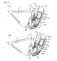
- Figure 3 shows a bucket position with a first and a second position of the stop element.
- the representation 3A and the representation 3B show a bucket 5 in a maximum inwards pivoting position of the take-up element 24, i.e. a projection 232 arranged on the knee joint 23 is in contact with the stop element 4.
- the stop element 4 is composed of a contact area 41 and a fixing area 42.
- the contact area 41 of the stop element 4 in this situation has a first area 41' and a second area 41".
- the shape of the contact area 41, in particular of the first area 41' and of the second area 41" can, for example, be selected in such a way that, starting from the first area 41' with a constant initial thickness, at which the bucket 5 is brought into the maximum inwards pivoting position, the thickness of the stop element 4 increases, for example in linear fashion, to an end thickness in the second area 41 ", in which the bucket 5 is brought into such an inwards pivoting position which is smaller than the maximum inwards pivoting position, and at the same time ensures that the objects located in the bucket 5 do not collide with the tilting hydraulic cylinders 21
- the thickness of the first and/or second areas 41', 41" therefore determines the inwards pivoting position of the bucket 5, wherein the inwards pivoting position becomes smaller as the thickness of the stop element increases.
- the fixing area 42 of the stop element 4 is firmly secured to the contact area 41, for example by welding.
- the fixing area 42 in this embodiment example further has two cut-outs 43, 43' in the form of holes. By means of these cut-outs 43, 43', and the fixing element 45 arranged on the lift arm 22, the stop element 4 can be fixed on the lift arm 22, for example by means of a fixing pin.
- the distance interval between the two cut-outs 43, 43' in this situation is selected in such a way that the projection 232 is in connection with the contact area 41 in such a way that the bucket can attain, either for the first position of the stop element 4, its maximum inwards pivoting position, or, for the second position of the stop element 4, a lesser inwards pivoting position, determined by the shape of the contact area 41.
- the representation 3A in this situation represents the position of the stop element 4 for the situation in which there is no object present inside the bucket 5, which could strike against the tilting hydraulic cylinder 21.
- the projection 232 is therefore in connection with the first area in such a way that the bucket 5 can be brought into the maximum inwards pivoting position.
- the representation 3B is intended to present the situation in which the bucket 5 has objects shaped in such a way that they could collide with the tilting hydraulic cylinder 21.
- the projection 232 is in contact with the second area 41" in such a way that the bucket 5 can be brought into an inwards pivoting position determined by the shape of the contact area.
Landscapes
- Engineering & Computer Science (AREA)
- Mechanical Engineering (AREA)
- Mining & Mineral Resources (AREA)
- Civil Engineering (AREA)
- General Engineering & Computer Science (AREA)
- Structural Engineering (AREA)
- Operation Control Of Excavators (AREA)
- Forklifts And Lifting Vehicles (AREA)
- Harvester Elements (AREA)
Applications Claiming Priority (1)
| Application Number | Priority Date | Filing Date | Title |
|---|---|---|---|
| DE102007048330A DE102007048330A1 (de) | 2007-10-09 | 2007-10-09 | Nutzfahrzeug mit einem Anschlagelement für einen Frontlader |
Publications (2)
| Publication Number | Publication Date |
|---|---|
| EP2048289A2 true EP2048289A2 (de) | 2009-04-15 |
| EP2048289A3 EP2048289A3 (de) | 2017-03-01 |
Family
ID=40278661
Family Applications (1)
| Application Number | Title | Priority Date | Filing Date |
|---|---|---|---|
| EP08253087.4A Withdrawn EP2048289A3 (de) | 2007-10-09 | 2008-09-19 | Nutzfahrzeug mit einem Anschlagelement an einem Frontlader |
Country Status (2)
| Country | Link |
|---|---|
| EP (1) | EP2048289A3 (de) |
| DE (1) | DE102007048330A1 (de) |
Family Cites Families (6)
| Publication number | Priority date | Publication date | Assignee | Title |
|---|---|---|---|---|
| US3867750A (en) * | 1973-09-27 | 1975-02-25 | Clark Equipment Co | Machinery stop and method of installation |
| DE9208777U1 (de) * | 1991-10-30 | 1993-03-04 | O & K Orenstein & Koppel Ag, 1000 Berlin | Einrichtung zum elastischen Dämpfen des Stoßes von zwei sich aufeinander zu bewegenden Bauteilen |
| DE19755616C1 (de) * | 1997-12-13 | 1999-06-02 | Orenstein & Koppel Ag | Verstelleinrichtung für ein bewegliches Arbeitsgerät einer mobilen Arbeitsmaschine |
| US6461099B1 (en) * | 2000-10-16 | 2002-10-08 | Caterpillar Inc | Loader linkage with rack stops |
| US6886279B2 (en) * | 2000-10-23 | 2005-05-03 | Jrb Company, Inc. | Loader coupler with adjustable dump and roll-back stops |
| JP4314368B2 (ja) * | 2004-05-21 | 2009-08-12 | ヤンマー建機株式会社 | 積込み装置 |
-
2007
- 2007-10-09 DE DE102007048330A patent/DE102007048330A1/de not_active Ceased
-
2008
- 2008-09-19 EP EP08253087.4A patent/EP2048289A3/de not_active Withdrawn
Also Published As
| Publication number | Publication date |
|---|---|
| DE102007048330A1 (de) | 2009-04-23 |
| EP2048289A3 (de) | 2017-03-01 |
Similar Documents
| Publication | Publication Date | Title |
|---|---|---|
| EP2719835B1 (de) | Arbeitsmaschine mit auslegerarretiersystem und zugehöriges verfahren | |
| CN104010484B (zh) | 裂土器组件 | |
| EP2596179B1 (de) | Grabenbagger mit einer abnehmbaren daumenanordnung | |
| EP1775389A1 (de) | Ladevorrichtung | |
| SE522817C2 (sv) | Metod för förflyttning av underkörningsskydd samt arrangemang vid underkörningsskydd för fordon | |
| CN107874846B (zh) | 手术显微镜用支架装置 | |
| EP2319995B1 (de) | Vorrichtung zum Bewegen einer Plattform. | |
| EP2733018A1 (de) | Klappbare Fahrzeugrückspiegel | |
| JP5512151B2 (ja) | アーム連結型草刈機 | |
| US20070003395A1 (en) | Device in a vehicle adapted to handle loads | |
| US20020139545A1 (en) | Construction vehicle with a working appliance | |
| EP1842412B1 (de) | Traktorfrontanbauvorrichtungen | |
| CN110654287B (zh) | 用于车辆座椅的腿部支撑件 | |
| CN114174117A (zh) | 远程可伸缩镜子 | |
| EP2140748B1 (de) | Kupplungen für einen Traktor | |
| EP2189578B1 (de) | Zusatzplaniergerüst für konvertierbare Baumaschine | |
| US6955229B1 (en) | Implement pitch-yaw system | |
| CN113073691B (zh) | 用于作业机械的摇臂装置 | |
| EP3600203B1 (de) | Kippanordnung für einen elektrisch angetriebenen rollstuhl und ein elektrisch angetriebener rollstuhl damit | |
| EP0982439B1 (de) | Frontladerausleger | |
| CN113039095B (zh) | 用于作业机器的可调后视镜组件 | |
| EP3864224B1 (de) | Zwei im wesentlichen parallele hubarme einer arbeitsmaschine verbindende und sich dazwischen erstreckende querträgeranordnung | |
| CN109228968A (zh) | 工作操纵系统随动的轮式装载机座椅 | |
| JP2003095589A (ja) | 荷役運搬車両 | |
| US20080247853A1 (en) | Multifunctional bushing connection between liftgate platform and load transfer members |
Legal Events
| Date | Code | Title | Description |
|---|---|---|---|
| PUAI | Public reference made under article 153(3) epc to a published international application that has entered the european phase |
Free format text: ORIGINAL CODE: 0009012 |
|
| AK | Designated contracting states |
Kind code of ref document: A2 Designated state(s): AT BE BG CH CY CZ DE DK EE ES FI FR GB GR HR HU IE IS IT LI LT LU LV MC MT NL NO PL PT RO SE SI SK TR |
|
| AX | Request for extension of the european patent |
Extension state: AL BA MK RS |
|
| PUAL | Search report despatched |
Free format text: ORIGINAL CODE: 0009013 |
|
| AK | Designated contracting states |
Kind code of ref document: A3 Designated state(s): AT BE BG CH CY CZ DE DK EE ES FI FR GB GR HR HU IE IS IT LI LT LU LV MC MT NL NO PL PT RO SE SI SK TR |
|
| AX | Request for extension of the european patent |
Extension state: AL BA MK RS |
|
| RIC1 | Information provided on ipc code assigned before grant |
Ipc: E02F 3/627 20060101ALI20170126BHEP Ipc: E02F 3/34 20060101ALI20170126BHEP Ipc: E02F 3/36 20060101AFI20170126BHEP |
|
| 17P | Request for examination filed |
Effective date: 20170901 |
|
| RBV | Designated contracting states (corrected) |
Designated state(s): AT BE BG CH CY CZ DE DK EE ES FI FR GB GR HR HU IE IS IT LI LT LU LV MC MT NL NO PL PT RO SE SI SK TR |
|
| AKX | Designation fees paid |
Designated state(s): AT BE BG CH CY CZ DE DK EE ES FI FR GB GR HR HU IE IS IT LI LT LU LV MC MT NL NO PL PT RO SE SI SK TR |
|
| AXX | Extension fees paid |
Extension state: AL Extension state: MK Extension state: RS Extension state: BA |
|
| STAA | Information on the status of an ep patent application or granted ep patent |
Free format text: STATUS: THE APPLICATION IS DEEMED TO BE WITHDRAWN |
|
| 18D | Application deemed to be withdrawn |
Effective date: 20170902 |