EP2048314B1 - Combinaison d'un isolation, un élément d'un bâtiment et une bande de crépissage pour le passage entre un cadre de fenêtre ou un cadre de porte et une isolation thermique - Google Patents
Combinaison d'un isolation, un élément d'un bâtiment et une bande de crépissage pour le passage entre un cadre de fenêtre ou un cadre de porte et une isolation thermique Download PDFInfo
- Publication number
- EP2048314B1 EP2048314B1 EP08017678.7A EP08017678A EP2048314B1 EP 2048314 B1 EP2048314 B1 EP 2048314B1 EP 08017678 A EP08017678 A EP 08017678A EP 2048314 B1 EP2048314 B1 EP 2048314B1
- Authority
- EP
- European Patent Office
- Prior art keywords
- thermal insulation
- plaster
- strip
- edge strip
- combination according
- Prior art date
- Legal status (The legal status is an assumption and is not a legal conclusion. Google has not performed a legal analysis and makes no representation as to the accuracy of the status listed.)
- Not-in-force
Links
- 238000009413 insulation Methods 0.000 title claims description 65
- 230000007704 transition Effects 0.000 title claims description 7
- 239000011505 plaster Substances 0.000 claims description 80
- 239000000853 adhesive Substances 0.000 claims description 3
- 230000001070 adhesive effect Effects 0.000 claims description 3
- 150000001875 compounds Chemical class 0.000 claims description 3
- 239000000945 filler Substances 0.000 claims description 3
- 238000003780 insertion Methods 0.000 claims description 3
- 230000037431 insertion Effects 0.000 claims description 3
- 230000003111 delayed effect Effects 0.000 claims description 2
- 239000004744 fabric Substances 0.000 claims description 2
- 230000003014 reinforcing effect Effects 0.000 claims description 2
- 238000000465 moulding Methods 0.000 description 30
- 238000005520 cutting process Methods 0.000 description 9
- 230000001681 protective effect Effects 0.000 description 5
- 230000000694 effects Effects 0.000 description 4
- 239000011440 grout Substances 0.000 description 4
- 239000000463 material Substances 0.000 description 4
- 238000004140 cleaning Methods 0.000 description 3
- 239000004743 Polypropylene Substances 0.000 description 2
- 239000006260 foam Substances 0.000 description 2
- 239000004033 plastic Substances 0.000 description 2
- 229920003023 plastic Polymers 0.000 description 2
- 229920001155 polypropylene Polymers 0.000 description 2
- 239000004800 polyvinyl chloride Substances 0.000 description 2
- 238000007789 sealing Methods 0.000 description 2
- 238000003466 welding Methods 0.000 description 2
- 241000238631 Hexapoda Species 0.000 description 1
- 239000004793 Polystyrene Substances 0.000 description 1
- 239000002390 adhesive tape Substances 0.000 description 1
- 230000004888 barrier function Effects 0.000 description 1
- 238000006073 displacement reaction Methods 0.000 description 1
- 229920006248 expandable polystyrene Polymers 0.000 description 1
- 238000001125 extrusion Methods 0.000 description 1
- 239000002657 fibrous material Substances 0.000 description 1
- 239000003365 glass fiber Substances 0.000 description 1
- 239000003292 glue Substances 0.000 description 1
- 238000004519 manufacturing process Methods 0.000 description 1
- -1 polypropylene Polymers 0.000 description 1
- 229920002635 polyurethane Polymers 0.000 description 1
- 239000004814 polyurethane Substances 0.000 description 1
- 229920000915 polyvinyl chloride Polymers 0.000 description 1
- 238000005096 rolling process Methods 0.000 description 1
- 239000004834 spray adhesive Substances 0.000 description 1
- 239000011345 viscous material Substances 0.000 description 1
Images

Classifications
-
- E—FIXED CONSTRUCTIONS
- E04—BUILDING
- E04F—FINISHING WORK ON BUILDINGS, e.g. STAIRS, FLOORS
- E04F13/00—Coverings or linings, e.g. for walls or ceilings
- E04F13/02—Coverings or linings, e.g. for walls or ceilings of plastic materials hardening after applying, e.g. plaster
- E04F13/04—Bases for plaster
- E04F13/06—Edge-protecting borders
- E04F13/068—Edge-protecting borders combined with mesh material or the like to allow plaster to bond therewith
-
- E—FIXED CONSTRUCTIONS
- E06—DOORS, WINDOWS, SHUTTERS, OR ROLLER BLINDS IN GENERAL; LADDERS
- E06B—FIXED OR MOVABLE CLOSURES FOR OPENINGS IN BUILDINGS, VEHICLES, FENCES OR LIKE ENCLOSURES IN GENERAL, e.g. DOORS, WINDOWS, BLINDS, GATES
- E06B1/00—Border constructions of openings in walls, floors, or ceilings; Frames to be rigidly mounted in such openings
- E06B1/62—Tightening or covering joints between the border of openings and the frame or between contiguous frames
-
- E—FIXED CONSTRUCTIONS
- E04—BUILDING
- E04F—FINISHING WORK ON BUILDINGS, e.g. STAIRS, FLOORS
- E04F13/00—Coverings or linings, e.g. for walls or ceilings
- E04F13/02—Coverings or linings, e.g. for walls or ceilings of plastic materials hardening after applying, e.g. plaster
- E04F13/04—Bases for plaster
- E04F13/06—Edge-protecting borders
- E04F2013/063—Edge-protecting borders for corners
-
- E—FIXED CONSTRUCTIONS
- E06—DOORS, WINDOWS, SHUTTERS, OR ROLLER BLINDS IN GENERAL; LADDERS
- E06B—FIXED OR MOVABLE CLOSURES FOR OPENINGS IN BUILDINGS, VEHICLES, FENCES OR LIKE ENCLOSURES IN GENERAL, e.g. DOORS, WINDOWS, BLINDS, GATES
- E06B1/00—Border constructions of openings in walls, floors, or ceilings; Frames to be rigidly mounted in such openings
- E06B1/62—Tightening or covering joints between the border of openings and the frame or between contiguous frames
- E06B2001/624—Tightening or covering joints between the border of openings and the frame or between contiguous frames with parts to be embedded in the stucco layer or otherwise linked to this layer
-
- E—FIXED CONSTRUCTIONS
- E06—DOORS, WINDOWS, SHUTTERS, OR ROLLER BLINDS IN GENERAL; LADDERS
- E06B—FIXED OR MOVABLE CLOSURES FOR OPENINGS IN BUILDINGS, VEHICLES, FENCES OR LIKE ENCLOSURES IN GENERAL, e.g. DOORS, WINDOWS, BLINDS, GATES
- E06B1/00—Border constructions of openings in walls, floors, or ceilings; Frames to be rigidly mounted in such openings
- E06B1/62—Tightening or covering joints between the border of openings and the frame or between contiguous frames
- E06B2001/626—Tightening or covering joints between the border of openings and the frame or between contiguous frames comprising expanding foam strips
Definitions
- the invention relates to a plaster molding, which is positioned at the transition between a mounted on a building thermal insulation and a built-in or to be incorporated building component, such as window frames or door frames.
- plaster strips are known in manifold versions. So far, the plaster strips were usually attached to the building component, z. B. by a foam adhesive tape. This attachment has kept the grout bar positioned until then the grout has been connected by means of filler and / or plaster compound to the insulation in a subsequent operation, which represents an additional attachment of the plaster.
- EP 1 793 061 A2 discloses a combination of a thermal insulation, a window frame and a plaster molding according to the preamble of claim 1.
- the invention has for its object to provide a way to make it possible - apart from any connection of the plaster molding to the insulation by means of filler and / or plastering compound - can hold the plaster molding in its functional position.
- the invention provides that the plaster strip is attached according to the characterizing part of claim 1 to the thermal insulation. If the plaster molding is connected by means of putty and / or plaster to the insulation (completely finished functional state) or if the plaster strip is to be subsequently connected by means of putty and / or plaster to the insulation (intermediate state), so represents the attachment of the plaster strip according to the invention to the thermal insulation a contrast additional attachment.
- the inventive Fastening the plasterboard to the thermal insulation primarily fulfills the purpose of keeping the screed positioned, so that the connection to the thermal insulation can be created by means of putty and / or plaster mass comfortable and without risk of unwanted displacement of the plaster molding. After creating the connection, the attachment according to the invention can become a subordinate attachment.
- the attachment according to the invention to the thermal insulation has a permanently relevant attachment function.
- transition between thermal insulation and window frame or door frame is not the only place where the plasterboard positioned according to the invention can be used.
- Further examples of building components which are suitable for the design of the transition by means of the plaster molding are beams emerging from the building sump, window sills, etc.
- a fundamentally novel feature of the invention is that, as a result of its fastening, if necessary in addition, as a result of its connection, the plastering strip practically becomes part of the thermal insulation. It is more decoupled from the built-in building component than in the prior art. Preferably, there is no attachment of the plaster strip to the built-in building component. The risk that damage due to different movements of window frame and insulation or plaster on the insulation result, for. B. by the heavy slamming of window sashes is minimized.
- the plaster molding is fixed in such positioning on the thermal insulation that it is in contact with the built-in building component.
- the functional relationship between the built-in building component and the plaster bar is preserved.
- the attachment according to the invention of the plaster strip to the thermal insulation comprises, for the practice particularly easy to handle and thereby providing the required strength of the attachment, the insertion of several Wegragvorsprünge the plaster strip in the insulation inside. It is advantageous if the Wegragvorsprünge have relatively small thickness compared to their other dimensions; this improves the ease of manufacture of the plaster strip and causes the plaster strip is particularly easy to attach to the thermal insulation.
- an adhesive bond between the thermal insulation and the cleaning strip preferably with a spray adhesive as an adhesive may be provided.
- the heat insulation on a groove in which the Wegragschenkel or the Wegragvorsprünge sits (sit).
- the groove excludes incorrect positioning of the plaster strip, the insertion of the Wegragschenkels or the Wegragvorsprünge in the groove is an extremely simple way of creating the attachment according to the invention.
- At least a portion of the Wegragvorsprünge has one or more barb-like projections. As a result, the resistance to undesired loosening of the attachment of the plaster strip is increased to the thermal insulation.
- the screed has an area which projects into a gap between the thermal insulation and the built-in building component.
- a gap is practically always present in more or less large width between the thermal insulation and the built-in building component. As a rule, it is not uniformly wide if one continues along the gap.
- the introduction of a portion of the plaster molding in this gap can be used for a later to be described in more detail sealing function.
- said screed area is clamped in the gap.
- barb-like approach in said screed area on the side facing the heat insulation is used to increase the loosening resistance of the quasi-attachment and the comfortable Einbringiana the area in the gap.
- the plaster molding has a expansion expansion expansion strip located between it and the built-in building component.
- the expansion strip may be located in said screed area projecting into the gap between the front end of the thermal insulation and the built-in building component.
- Expansion expansion expansion strips are known and available on the market. These are usually foam strips soaked in a viscous material. Such expansion strips have in connection with the plaster strip according to the invention the advantage that with their help, when the expansion strip has been cleared for expansion, the space between two boundaries, in which the expansion strip is located, can be fully filled. This leads to a local sealing function, but also to a local, at least certain definition function.
- the expanded expansion strip in the delivery state of the plaster strip is enclosed at least from two opposite sides and this inclusion can be canceled by removing or moving away a wall of the containment space. Then the expansion strip is free for expansion.
- the removal wall or Wegschulswand is preferably made in one piece with the plaster molding. The execution can either be such that it remains after the release of the expansion strip as part of the plaster molding. Or the design may be such that when releasing the expansion strip, it is completely removed from or separated from the remaining plasterboard.
- the plaster strip preferably has a covering lip for a gap between the plastering strip and the built-in building component.
- the cover lip provides a barrier against the intrusion of unwanted things, such as dirt or small insects, into the gap In addition, depending on the shape of the plaster molding, this can improve the appearance of this transition between the built-in building component and the plaster molding.
- the cover lip is preferably formed of a softer material than the other plaster strip and / or elastic-flexible. The cover lip is preferably produced by coextrusion with the rest of the plastering strip.
- the plaster strip on a first leg which rests flat against the outside of the insulation. This leads to a particularly secure position and stable union of the plaster molding with the thermal insulation.
- the plaster molding has a second leg, which carries in a direction away from the outside of the thermal insulation. The second leg is usually a limit to the end of the applied plaster layer.
- the plaster molding can have a channel profiling to improve the plaster adhesion. Also, openings in the plaster molding, through which putty and / or plaster can pass from the area directly on the surface of the thermal insulation and the area a little further away from the surface of the thermal insulation, are possible.
- the plaster molding has a protective tab on which a protective film for the built-in building component can be fastened.
- a protective tab on which a protective film for the built-in building component can be fastened.
- the grout has a Arm michsgewebeabêt, which is preferably secured to it with a welded connection.
- the Arm michsgewebeabites is connected with putty and / or plaster to the thermal insulation. He perfects the fixation of the plaster molding on the thermal insulation, but also ensures the permanent crack-free of the applied to the thermal insulation plaster layer.
- the thermal insulation can in particular made of foamed polystyrene, foamed polyurethane or fiber material, which has been made dimensionally stable by introduced plastic.
- Another object, not part of the invention, is a tool for producing a groove in a thermal insulation, which is attached to a building and extends to the vicinity of a built-in or to be incorporated building component, such as window frames or door frames, wherein the groove is suitable for inserting a Wegragschenkels a plaster molding or several Wegragvorsprünge a plaster molding, the tool a Anleg Scheme that can be applied to the building component and the tool when moving the tool along the building component leads, and a cutting area for cutting the groove when moving the tool along the building component has.
- the groove which is particularly convenient for the attachment of the plaster molding to the thermal insulation, can be produced in a simple manner at the correct place and with correct course.
- the tool attaches to the building component, in particular window frames or door frames, and moves the tool along the built-in building component in the direction of the course of the groove to be created. You can either move the tool a single time in the longitudinal direction of the built building component or perform the cutting of the groove in several successive movements.
- the groove thus created runs perfectly parallel to the built-in building component.
- the actual cutting component of the tool can be designed as a kind of small saw.
- the movement of the tool along the built-in building component can be made sliding, alternatively rolling on small rolls.
- sliding sliding it is advantageous if the Anleg Schl has a covering of a felt-like material.
- the tool can be moved particularly pleasant by hand.
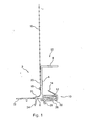
- Fig. 1 drawn plaster strip 2 has a first leg 4, the in Fig. 1 from bottom to top, and a second leg 6, which in Fig. 1 essentially from right to left leads up.
- a Wegragschenkel 8 At the top End of the first leg 4 is a Wegragschenkel 8 at right angles to the right.
- a substantially rectangular inclusion region 10 for expansion strip 12 with delayed expansion adjoins to the right.
- a barb-like projection 14 On top of the enclosure area 10 is a barb-like projection 14.
- the lower part of the first leg 4 is provided on its left side with a channel profiling 20, as well as the upper side of the second leg 6.
- the transition between the first leg 4 and the second leg 6 is rounded.
- a protective strap 22 connects.
- On the upper side of the protective tab 22 is a not shown, double-sided tape, so you can easily stick a protective film there.
- a lower wall 26 of the confinement region 10 is latched on the left and right behind recesses of the adjacent parts of the confinement region 10.
- the lower wall 26 can be released from the latches left and right and either z.
- the expansion strip 12 is free for slow expansion.
- the wall 26 and the connection 30 have been made in one piece with the remainder of the plaster strip 2, in a condition in which the wall 26 is inclined by about 90 ° or more Clockwise compared to Fig. 1 drawn situation was pivoted. In this state, the expansion strip 12 could be easily inserted and then the lower wall 26 closed and locked.
- the cleaning strip 2 has been prepared by extrusion.
- the cover lip 24 consists of over the remaining plaster molding softer, flexible material and has been prepared by coextrusion.
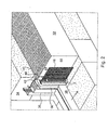
- Fig. 2 you can see how the plaster strip 2 is being attached to a heat insulation 32. It can also be seen a small part of a building wall 34 and a part of a window frame 36 which is inserted into a corresponding opening of the building wall 34. There is a gap 42 between the outer surface 38 of the window frame 36 directed towards the outside (arrow A) and a mounting surface 40 of the thermal insulation 32 facing the building wall (arrow 1). The inclusion region 10 of the plaster molding strip 2 is introduced into this gap, after previously whose bottom wall 26 has been removed.
- a vertically extending groove 46 having a depth of z. B. 10 to 20 mm.
- the groove 46 has a slightly smaller width than the Wegragschenkel 8 is thick (measured from bottom to top in Fig. 1 ).
- the groove 46 has previously been cut by means of a tool to be described later in the soffit surface 44, and that at a defined distance from the outer side 38 of the window frame 36th
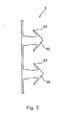
- Fig. 3 is facing like arrow III in Fig. 1 a patented execution of plasterboard 2 shown.
- a continuous Wegragschenkels 8 individual, spaced apart Wegragvorsprünge 50, each with two barb-like projections 52, are provided.
- this plaster strip 2 can be more easily pressed into the insulation 32, as if it has a continuous Wegragschenkel 8.
- Fig. 4 shows a simple, not forming part of the invention, only by hand force tool 54 for generating the groove 46, in cross section.
- Right-angled to the plane of the drawing Fig. 4 is the tool 54 z. B. 10 to 20 cm long.
- the tool 54 is moved in a direction perpendicular to the plane of the drawing Fig. 4 runs in a vertical direction along the in Fig. 2 drawn vertical leg 56 of the window frame 36 shifted to produce by "sawing" the groove 46.
- the tool 54 has an application area 58, which is located at the top in FIG Fig. 4 is provided with a felt-like support 60. With the felt-like support 60, the tool 54 slides in its use on the outside of the leg 56 of the window frame 36 along.
- the tool 54 has a curved handle portion 62 which is grooved so that it can be safely gripped and the tool 54 can be handled comfortably.
- the tool 54 In a cutting area 64, which at its right in Fig. 4 pointing end like a small saw with saw teeth 66 is formed.
- the "saw” extends in a straight line in a direction perpendicular to the plane of the drawing Fig. 4 ,
- the cutting area 64 will work deeper and deeper into the thermal insulation 32. Accordingly, the application area 58 on the window frame 36 moves ever closer to the reveal surface 44, until it rests with its surface 68 thereto. Now, the desired depth of the groove 46 is reached.
- Preferred materials for the grout 2, apart from Arm michsgewebe 16, Espansionsstsammlung 12, Abdecklippe 24 are polyvinyl chloride (PVC), polypropylene (PP) and polystyrene (PS).
- the reinforcing fabric 16 is preferably made of glass fiber strands, coated with plastic.
- the cover lip is preferably made of soft PVC.
Landscapes
- Engineering & Computer Science (AREA)
- Architecture (AREA)
- Civil Engineering (AREA)
- Structural Engineering (AREA)
- Building Environments (AREA)
- Wing Frames And Configurations (AREA)
- Door And Window Frames Mounted To Openings (AREA)
Claims (10)
- Combinaison(a) d'une isolation thermique (32) fixée à un bâtiment (34),(b) et d'un élément de bâtiment encastré tel qu'un cadre de fenêtre (36) ou un cadre de porte,(c) et d'une baguette pour crépi (2) qui est positionnée au niveau de la transition entre l'isolation thermique (32) et l'élément de bâtiment encastré, et qui est fixée à l'isolation thermique (32), indépendamment d'une éventuelle liaison déjà réalisée ou qu'il reste à réaliser entre ladite baguette pour crépi (2) et l'isolation thermique (32) à l'aide d'un enduit et/ou d'une masse de crépi,caractérisée en ce que la baguette pour crépi (2) est fixée à l'isolation thermique (32) à l'aide de plusieurs saillies (50) qui sont calées dans l'isolation thermique (32) sous la forme de fixations à enfichage et dont quelques-unes au moins présentent un ou plusieurs rebords en forme de crochets de retenue (52).
- Combinaison selon la revendication 1, caractérisée en ce qu'une liaison par collage se trouve en supplément entre l'isolation thermique (32) et la baguette pour crépi (2).
- Combinaison selon la revendication 1 ou 2, caractérisée en ce que la baguette pour crépi (2) présente une zone qui dépasse dans un interstice (42) entre l'isolation thermique (32) et l'élément de bâtiment encastré.
- Combinaison selon la revendication 3, caractérisée en ce que la zone est calée dans l'interstice (42) par serrage.
- Combinaison selon la revendication 3 ou 4, caractérisée en ce que la zone présente un rebord en forme de crochet de retenue (14) sur le côté tourné vers l'isolation thermique (32).
- Combinaison selon l'une des revendications 1 à 5, caractérisée en ce que la baguette pour crépi (2) présente une bande d'expansion (12) à expansion retardée qui se trouve entre elle et l'élément de bâtiment encastré.
- Combinaison selon la revendication 6 et l'une des revendications 3 à 5, caractérisée en ce que la bande d'expansion (2) se trouve sur ladite zone.
- Combinaison selon l'une des revendications 1 à 7, caractérisée en ce que la baguette pour crépi (2) présente une première branche (4) qui est appliquée à plat sur le côté extérieur (44) de l'isolation thermique (32).
- Combinaison selon l'une des revendications 1 à 8, caractérisée en ce que la baguette pour crépi (2) présente une partie en tissu d'armature (16) fixée sur elle.
- Combinaison selon l'une des revendications 1 à 9, caractérisée en ce que la baguette pour crépi (2) présente une lèvre de recouvrement (24), de préférence flexible, pour un interstice entre la baguette pour crépi (2) et l'élément de bâtiment encastré.
Applications Claiming Priority (1)
| Application Number | Priority Date | Filing Date | Title |
|---|---|---|---|
| DE102007048311.4A DE102007048311B4 (de) | 2007-10-09 | 2007-10-09 | Anputzleiste für den Übergang zwischen einem Fensterrahmen oder Türrahmen und einer Wärmedämmung |
Publications (3)
| Publication Number | Publication Date |
|---|---|
| EP2048314A2 EP2048314A2 (fr) | 2009-04-15 |
| EP2048314A3 EP2048314A3 (fr) | 2012-10-03 |
| EP2048314B1 true EP2048314B1 (fr) | 2014-08-27 |
Family
ID=39992953
Family Applications (1)
| Application Number | Title | Priority Date | Filing Date |
|---|---|---|---|
| EP08017678.7A Not-in-force EP2048314B1 (fr) | 2007-10-09 | 2008-10-08 | Combinaison d'un isolation, un élément d'un bâtiment et une bande de crépissage pour le passage entre un cadre de fenêtre ou un cadre de porte et une isolation thermique |
Country Status (2)
| Country | Link |
|---|---|
| EP (1) | EP2048314B1 (fr) |
| DE (1) | DE102007048311B4 (fr) |
Families Citing this family (6)
| Publication number | Priority date | Publication date | Assignee | Title |
|---|---|---|---|---|
| DE102005057778A1 (de) * | 2005-12-02 | 2007-06-06 | August Braun | Putzabschlussleiste für eine Putzschicht auf einer Wärmedämmung |
| DE102009034445A1 (de) * | 2009-07-23 | 2011-01-27 | August Braun | Einteilige Abdicht- oder Anputzleiste |
| CN103556903B (zh) * | 2013-11-25 | 2015-08-19 | 哈尔滨森鹰窗业股份有限公司 | 一种被动式窗口安装结构 |
| CN107558869A (zh) * | 2017-09-14 | 2018-01-09 | 中国建筑局(集团)有限公司 | 一种窗边海绵保温收边结构、连接构造及其施工方法 |
| DE102018105610A1 (de) * | 2018-03-12 | 2019-09-12 | August Braun | Anputzleiste zur Anordnung an einem Gebäude-Übergang sowie Gebäude-Übergang damit |
| EP3822426B1 (fr) * | 2019-11-12 | 2022-01-26 | Braun, August | Profil couvre-joint en matière plastique à risque de flamme réduit |
Family Cites Families (6)
| Publication number | Priority date | Publication date | Assignee | Title |
|---|---|---|---|---|
| DE29607346U1 (de) * | 1996-04-23 | 1996-07-11 | Jörder, Rolf, 68753 Waghäusel | Anschlußprofil zwischen Fensterrahmen und Mauerwerksputz im Bereich einer Fensterlaibung |
| DE20319109U1 (de) * | 2003-12-10 | 2005-05-12 | Knauf Marmorit Gmbh | Dämmung für eine Gebäudewand |
| DE102004042301B4 (de) * | 2004-08-27 | 2014-01-30 | Deutsche Amphibolin-Werke Von Robert Murjahn Stiftung & Co Kg | Dichtprofil zur kantenumfassenden Anbringung an freien Rändern von Wärmedämmplatten |
| AT501439B1 (de) * | 2004-12-29 | 2009-07-15 | Peter Kassmannhuber | Laibungsanschlussprofil für an putz und an eine dämmschicht angrenzende bauteile |
| DE102005057778A1 (de) * | 2005-12-02 | 2007-06-06 | August Braun | Putzabschlussleiste für eine Putzschicht auf einer Wärmedämmung |
| DE102006062701A1 (de) * | 2006-05-19 | 2007-12-13 | August Braun | Gebäude-Wärmedämmungsanordnung |
-
2007
- 2007-10-09 DE DE102007048311.4A patent/DE102007048311B4/de active Active
-
2008
- 2008-10-08 EP EP08017678.7A patent/EP2048314B1/fr not_active Not-in-force
Also Published As
| Publication number | Publication date |
|---|---|
| EP2048314A3 (fr) | 2012-10-03 |
| DE102007048311A1 (de) | 2009-04-23 |
| DE102007048311B4 (de) | 2022-08-11 |
| EP2048314A2 (fr) | 2009-04-15 |
Similar Documents
| Publication | Publication Date | Title |
|---|---|---|
| EP0628121B1 (fr) | Bande de crepissage et de protection pour chassis de fenetre, batis de porte ou analogue pour la jonction avec le crepi | |
| EP2404008B1 (fr) | Dispositif d'étanchéité sur un joint dans une construction | |
| EP2048314B1 (fr) | Combinaison d'un isolation, un élément d'un bâtiment et une bande de crépissage pour le passage entre un cadre de fenêtre ou un cadre de porte et une isolation thermique | |
| EP2281971B1 (fr) | Baguette de bord pour une couche d'enduit sur un élément d'isolation thermique | |
| WO1997030245A1 (fr) | Bande pour crepi pour chassis de fenetre, de porte ou similaire situee a l'interface avec le crepi | |
| DE19803034B4 (de) | Putzleiste mit daran befestigtem Armierungsmaterial | |
| EP1287218A1 (fr) | Profile | |
| EP0801189B1 (fr) | Profilé de raccord pour ouvertures de portes et fenêtres | |
| DE102004015556B4 (de) | Putzanschlussleiste für Fensterrahmen oder dgl. mit Basisteil und Anputzteil | |
| DE20008712U1 (de) | Profilleiste zum Abdichten einer Bewegungsfuge zwischen einem Bauteil und einer Putzschicht | |
| EP2492429B1 (fr) | Bande de crépissage ainsi qu'angles de construction dotés d'une bande de crépissage | |
| EP1627982A2 (fr) | Profilé de jonction | |
| DE20103282U1 (de) | Laibungsprofil zur Befestigung eines Abdeckmaterials an einer Gebäudeöffnung | |
| EP2270304B1 (fr) | Profilé d'enfichage et/ou d'introduction | |
| EP1905919B1 (fr) | Profilé de recouvrement de socle | |
| DE19709428A1 (de) | Anputzleiste für Fensterstöcke, Türstöcke oder dergleichen am Übergang zu Putz | |
| AT500337B1 (de) | Putzleiste mit armierungsgewebeabschnitt | |
| EP0558000B1 (fr) | Baquette profilée pour application et protection d'enduit à la jonction des cadres dormants de fenêtres, de portes ou semblable avec de l'enduit | |
| DE102023105542A1 (de) | Anputzdichtleiste | |
| EP1548222A1 (fr) | Profilé pour joindre une couche d'enduit ou de mortier de carrelage à un élément de construction | |
| DE7414512U (de) | Vorrichtung zur Festlegung von Türzargen und dergleichen | |
| EP4036347A1 (fr) | Profilé d'enduit avec une feuille d'enduit sur l'un de ses pieds d'enduit | |
| AT500205A1 (de) | Halterungsrahmen zur halternden verbindung zwischen einem fensterrahmen oder einem türrahmen und einer gebäudewand-öffnung | |
| EP0964108A2 (fr) | Habillage | |
| DE7827131U1 (de) | Laengsfuehrungsschiene fuer rollaeden |
Legal Events
| Date | Code | Title | Description |
|---|---|---|---|
| PUAI | Public reference made under article 153(3) epc to a published international application that has entered the european phase |
Free format text: ORIGINAL CODE: 0009012 |
|
| AK | Designated contracting states |
Kind code of ref document: A2 Designated state(s): AT BE BG CH CY CZ DE DK EE ES FI FR GB GR HR HU IE IS IT LI LT LU LV MC MT NL NO PL PT RO SE SI SK TR |
|
| AX | Request for extension of the european patent |
Extension state: AL BA MK RS |
|
| RIC1 | Information provided on ipc code assigned before grant |
Ipc: E04F 13/06 20060101ALI20120330BHEP Ipc: E06B 1/62 20060101AFI20120330BHEP |
|
| PUAL | Search report despatched |
Free format text: ORIGINAL CODE: 0009013 |
|
| AK | Designated contracting states |
Kind code of ref document: A3 Designated state(s): AT BE BG CH CY CZ DE DK EE ES FI FR GB GR HR HU IE IS IT LI LT LU LV MC MT NL NO PL PT RO SE SI SK TR |
|
| AX | Request for extension of the european patent |
Extension state: AL BA MK RS |
|
| RIC1 | Information provided on ipc code assigned before grant |
Ipc: E04F 13/06 20060101ALI20120828BHEP Ipc: E06B 1/62 20060101AFI20120828BHEP |
|
| 17P | Request for examination filed |
Effective date: 20130403 |
|
| AKX | Designation fees paid |
Designated state(s): AT BE BG CH CY CZ DE DK EE ES FI FR GB GR HR HU IE IS IT LI LT LU LV MC MT NL NO PL PT RO SE SI SK TR |
|
| GRAP | Despatch of communication of intention to grant a patent |
Free format text: ORIGINAL CODE: EPIDOSNIGR1 |
|
| INTG | Intention to grant announced |
Effective date: 20130628 |
|
| GRAS | Grant fee paid |
Free format text: ORIGINAL CODE: EPIDOSNIGR3 |
|
| GRAP | Despatch of communication of intention to grant a patent |
Free format text: ORIGINAL CODE: EPIDOSNIGR1 |
|
| INTG | Intention to grant announced |
Effective date: 20140313 |
|
| GRAA | (expected) grant |
Free format text: ORIGINAL CODE: 0009210 |
|
| AK | Designated contracting states |
Kind code of ref document: B1 Designated state(s): AT BE BG CH CY CZ DE DK EE ES FI FR GB GR HR HU IE IS IT LI LT LU LV MC MT NL NO PL PT RO SE SI SK TR |
|
| REG | Reference to a national code |
Ref country code: GB Ref legal event code: FG4D Free format text: NOT ENGLISH |
|
| REG | Reference to a national code |
Ref country code: CH Ref legal event code: EP |
|
| REG | Reference to a national code |
Ref country code: AT Ref legal event code: REF Ref document number: 684632 Country of ref document: AT Kind code of ref document: T Effective date: 20140915 |
|
| REG | Reference to a national code |
Ref country code: IE Ref legal event code: FG4D Free format text: LANGUAGE OF EP DOCUMENT: GERMAN |
|
| REG | Reference to a national code |
Ref country code: DE Ref legal event code: R096 Ref document number: 502008012146 Country of ref document: DE Effective date: 20141009 |
|
| REG | Reference to a national code |
Ref country code: LT Ref legal event code: MG4D |
|
| REG | Reference to a national code |
Ref country code: NL Ref legal event code: VDEP Effective date: 20140827 |
|
| PG25 | Lapsed in a contracting state [announced via postgrant information from national office to epo] |
Ref country code: GR Free format text: LAPSE BECAUSE OF FAILURE TO SUBMIT A TRANSLATION OF THE DESCRIPTION OR TO PAY THE FEE WITHIN THE PRESCRIBED TIME-LIMIT Effective date: 20141128 Ref country code: ES Free format text: LAPSE BECAUSE OF FAILURE TO SUBMIT A TRANSLATION OF THE DESCRIPTION OR TO PAY THE FEE WITHIN THE PRESCRIBED TIME-LIMIT Effective date: 20140827 Ref country code: LT Free format text: LAPSE BECAUSE OF FAILURE TO SUBMIT A TRANSLATION OF THE DESCRIPTION OR TO PAY THE FEE WITHIN THE PRESCRIBED TIME-LIMIT Effective date: 20140827 Ref country code: BG Free format text: LAPSE BECAUSE OF FAILURE TO SUBMIT A TRANSLATION OF THE DESCRIPTION OR TO PAY THE FEE WITHIN THE PRESCRIBED TIME-LIMIT Effective date: 20141127 Ref country code: FI Free format text: LAPSE BECAUSE OF FAILURE TO SUBMIT A TRANSLATION OF THE DESCRIPTION OR TO PAY THE FEE WITHIN THE PRESCRIBED TIME-LIMIT Effective date: 20140827 Ref country code: PT Free format text: LAPSE BECAUSE OF FAILURE TO SUBMIT A TRANSLATION OF THE DESCRIPTION OR TO PAY THE FEE WITHIN THE PRESCRIBED TIME-LIMIT Effective date: 20141229 Ref country code: NO Free format text: LAPSE BECAUSE OF FAILURE TO SUBMIT A TRANSLATION OF THE DESCRIPTION OR TO PAY THE FEE WITHIN THE PRESCRIBED TIME-LIMIT Effective date: 20141127 Ref country code: SE Free format text: LAPSE BECAUSE OF FAILURE TO SUBMIT A TRANSLATION OF THE DESCRIPTION OR TO PAY THE FEE WITHIN THE PRESCRIBED TIME-LIMIT Effective date: 20140827 |
|
| PG25 | Lapsed in a contracting state [announced via postgrant information from national office to epo] |
Ref country code: IS Free format text: LAPSE BECAUSE OF FAILURE TO SUBMIT A TRANSLATION OF THE DESCRIPTION OR TO PAY THE FEE WITHIN THE PRESCRIBED TIME-LIMIT Effective date: 20141227 Ref country code: HR Free format text: LAPSE BECAUSE OF FAILURE TO SUBMIT A TRANSLATION OF THE DESCRIPTION OR TO PAY THE FEE WITHIN THE PRESCRIBED TIME-LIMIT Effective date: 20140827 Ref country code: LV Free format text: LAPSE BECAUSE OF FAILURE TO SUBMIT A TRANSLATION OF THE DESCRIPTION OR TO PAY THE FEE WITHIN THE PRESCRIBED TIME-LIMIT Effective date: 20140827 Ref country code: CY Free format text: LAPSE BECAUSE OF FAILURE TO SUBMIT A TRANSLATION OF THE DESCRIPTION OR TO PAY THE FEE WITHIN THE PRESCRIBED TIME-LIMIT Effective date: 20140827 |
|
| PG25 | Lapsed in a contracting state [announced via postgrant information from national office to epo] |
Ref country code: NL Free format text: LAPSE BECAUSE OF FAILURE TO SUBMIT A TRANSLATION OF THE DESCRIPTION OR TO PAY THE FEE WITHIN THE PRESCRIBED TIME-LIMIT Effective date: 20140827 |
|
| PG25 | Lapsed in a contracting state [announced via postgrant information from national office to epo] |
Ref country code: EE Free format text: LAPSE BECAUSE OF FAILURE TO SUBMIT A TRANSLATION OF THE DESCRIPTION OR TO PAY THE FEE WITHIN THE PRESCRIBED TIME-LIMIT Effective date: 20140827 Ref country code: DK Free format text: LAPSE BECAUSE OF FAILURE TO SUBMIT A TRANSLATION OF THE DESCRIPTION OR TO PAY THE FEE WITHIN THE PRESCRIBED TIME-LIMIT Effective date: 20140827 Ref country code: RO Free format text: LAPSE BECAUSE OF FAILURE TO SUBMIT A TRANSLATION OF THE DESCRIPTION OR TO PAY THE FEE WITHIN THE PRESCRIBED TIME-LIMIT Effective date: 20140827 Ref country code: CZ Free format text: LAPSE BECAUSE OF FAILURE TO SUBMIT A TRANSLATION OF THE DESCRIPTION OR TO PAY THE FEE WITHIN THE PRESCRIBED TIME-LIMIT Effective date: 20140827 Ref country code: IT Free format text: LAPSE BECAUSE OF FAILURE TO SUBMIT A TRANSLATION OF THE DESCRIPTION OR TO PAY THE FEE WITHIN THE PRESCRIBED TIME-LIMIT Effective date: 20140827 Ref country code: SK Free format text: LAPSE BECAUSE OF FAILURE TO SUBMIT A TRANSLATION OF THE DESCRIPTION OR TO PAY THE FEE WITHIN THE PRESCRIBED TIME-LIMIT Effective date: 20140827 |
|
| REG | Reference to a national code |
Ref country code: DE Ref legal event code: R097 Ref document number: 502008012146 Country of ref document: DE |
|
| PG25 | Lapsed in a contracting state [announced via postgrant information from national office to epo] |
Ref country code: LU Free format text: LAPSE BECAUSE OF FAILURE TO SUBMIT A TRANSLATION OF THE DESCRIPTION OR TO PAY THE FEE WITHIN THE PRESCRIBED TIME-LIMIT Effective date: 20141008 Ref country code: MC Free format text: LAPSE BECAUSE OF FAILURE TO SUBMIT A TRANSLATION OF THE DESCRIPTION OR TO PAY THE FEE WITHIN THE PRESCRIBED TIME-LIMIT Effective date: 20140827 Ref country code: PL Free format text: LAPSE BECAUSE OF FAILURE TO SUBMIT A TRANSLATION OF THE DESCRIPTION OR TO PAY THE FEE WITHIN THE PRESCRIBED TIME-LIMIT Effective date: 20140827 |
|
| REG | Reference to a national code |
Ref country code: CH Ref legal event code: PL |
|
| PG25 | Lapsed in a contracting state [announced via postgrant information from national office to epo] |
Ref country code: BE Free format text: LAPSE BECAUSE OF NON-PAYMENT OF DUE FEES Effective date: 20141031 |
|
| PLBE | No opposition filed within time limit |
Free format text: ORIGINAL CODE: 0009261 |
|
| STAA | Information on the status of an ep patent application or granted ep patent |
Free format text: STATUS: NO OPPOSITION FILED WITHIN TIME LIMIT |
|
| GBPC | Gb: european patent ceased through non-payment of renewal fee |
Effective date: 20141127 |
|
| REG | Reference to a national code |
Ref country code: IE Ref legal event code: MM4A |
|
| PG25 | Lapsed in a contracting state [announced via postgrant information from national office to epo] |
Ref country code: CH Free format text: LAPSE BECAUSE OF NON-PAYMENT OF DUE FEES Effective date: 20141031 Ref country code: LI Free format text: LAPSE BECAUSE OF NON-PAYMENT OF DUE FEES Effective date: 20141031 |
|
| REG | Reference to a national code |
Ref country code: FR Ref legal event code: ST Effective date: 20150630 |
|
| 26N | No opposition filed |
Effective date: 20150528 |
|
| PG25 | Lapsed in a contracting state [announced via postgrant information from national office to epo] |
Ref country code: FR Free format text: LAPSE BECAUSE OF NON-PAYMENT OF DUE FEES Effective date: 20141031 |
|
| PG25 | Lapsed in a contracting state [announced via postgrant information from national office to epo] |
Ref country code: IE Free format text: LAPSE BECAUSE OF NON-PAYMENT OF DUE FEES Effective date: 20141008 Ref country code: GB Free format text: LAPSE BECAUSE OF NON-PAYMENT OF DUE FEES Effective date: 20141127 |
|
| PG25 | Lapsed in a contracting state [announced via postgrant information from national office to epo] |
Ref country code: SI Free format text: LAPSE BECAUSE OF FAILURE TO SUBMIT A TRANSLATION OF THE DESCRIPTION OR TO PAY THE FEE WITHIN THE PRESCRIBED TIME-LIMIT Effective date: 20140827 |
|
| PG25 | Lapsed in a contracting state [announced via postgrant information from national office to epo] |
Ref country code: HU Free format text: LAPSE BECAUSE OF FAILURE TO SUBMIT A TRANSLATION OF THE DESCRIPTION OR TO PAY THE FEE WITHIN THE PRESCRIBED TIME-LIMIT; INVALID AB INITIO Effective date: 20081008 Ref country code: TR Free format text: LAPSE BECAUSE OF FAILURE TO SUBMIT A TRANSLATION OF THE DESCRIPTION OR TO PAY THE FEE WITHIN THE PRESCRIBED TIME-LIMIT Effective date: 20140827 Ref country code: MT Free format text: LAPSE BECAUSE OF FAILURE TO SUBMIT A TRANSLATION OF THE DESCRIPTION OR TO PAY THE FEE WITHIN THE PRESCRIBED TIME-LIMIT Effective date: 20140827 |
|
| REG | Reference to a national code |
Ref country code: DE Ref legal event code: R082 Ref document number: 502008012146 Country of ref document: DE Representative=s name: SCHMITT-NILSON SCHRAUD WAIBEL WOHLFROM PATENTA, DE |
|
| REG | Reference to a national code |
Ref country code: DE Ref legal event code: R082 Ref document number: 502008012146 Country of ref document: DE Representative=s name: SCHMITT-NILSON SCHRAUD WAIBEL WOHLFROM PATENTA, DE Ref country code: DE Ref legal event code: R081 Ref document number: 502008012146 Country of ref document: DE Owner name: BRAUN, AUGUST, CZ Free format text: FORMER OWNER: BRAUN, AUGUST, SCHAFFHAUSEN, CH |
|
| PGFP | Annual fee paid to national office [announced via postgrant information from national office to epo] |
Ref country code: AT Payment date: 20181019 Year of fee payment: 11 |
|
| REG | Reference to a national code |
Ref country code: AT Ref legal event code: MM01 Ref document number: 684632 Country of ref document: AT Kind code of ref document: T Effective date: 20191008 |
|
| PG25 | Lapsed in a contracting state [announced via postgrant information from national office to epo] |
Ref country code: AT Free format text: LAPSE BECAUSE OF NON-PAYMENT OF DUE FEES Effective date: 20191008 |
|
| PGFP | Annual fee paid to national office [announced via postgrant information from national office to epo] |
Ref country code: DE Payment date: 20201214 Year of fee payment: 13 |
|
| REG | Reference to a national code |
Ref country code: DE Ref legal event code: R119 Ref document number: 502008012146 Country of ref document: DE |
|
| PG25 | Lapsed in a contracting state [announced via postgrant information from national office to epo] |
Ref country code: DE Free format text: LAPSE BECAUSE OF NON-PAYMENT OF DUE FEES Effective date: 20220503 |