EP2281971B1 - Baguette de bord pour une couche d'enduit sur un élément d'isolation thermique - Google Patents
Baguette de bord pour une couche d'enduit sur un élément d'isolation thermique Download PDFInfo
- Publication number
- EP2281971B1 EP2281971B1 EP10186069.0A EP10186069A EP2281971B1 EP 2281971 B1 EP2281971 B1 EP 2281971B1 EP 10186069 A EP10186069 A EP 10186069A EP 2281971 B1 EP2281971 B1 EP 2281971B1
- Authority
- EP
- European Patent Office
- Prior art keywords
- strip
- plaster
- expansion
- edge strip
- plaster edge
- Prior art date
- Legal status (The legal status is an assumption and is not a legal conclusion. Google has not performed a legal analysis and makes no representation as to the accuracy of the status listed.)
- Active
Links
Images

Classifications
-
- E—FIXED CONSTRUCTIONS
- E04—BUILDING
- E04G—SCAFFOLDING; FORMS; SHUTTERING; BUILDING IMPLEMENTS OR AIDS, OR THEIR USE; HANDLING BUILDING MATERIALS ON THE SITE; REPAIRING, BREAKING-UP OR OTHER WORK ON EXISTING BUILDINGS
- E04G21/00—Preparing, conveying, or working-up building materials or building elements in situ; Other devices or measures for constructional work
- E04G21/24—Safety or protective measures preventing damage to building parts or finishing work during construction
- E04G21/30—Safety or protective measures preventing damage to building parts or finishing work during construction against mechanical damage or dirt, e.g. guard covers of stairs
-
- E—FIXED CONSTRUCTIONS
- E04—BUILDING
- E04F—FINISHING WORK ON BUILDINGS, e.g. STAIRS, FLOORS
- E04F13/00—Coverings or linings, e.g. for walls or ceilings
- E04F13/02—Coverings or linings, e.g. for walls or ceilings of plastic materials hardening after applying, e.g. plaster
- E04F13/04—Bases for plaster
- E04F13/06—Edge-protecting borders
- E04F13/068—Edge-protecting borders combined with mesh material or the like to allow plaster to bond therewith
-
- E—FIXED CONSTRUCTIONS
- E06—DOORS, WINDOWS, SHUTTERS, OR ROLLER BLINDS IN GENERAL; LADDERS
- E06B—FIXED OR MOVABLE CLOSURES FOR OPENINGS IN BUILDINGS, VEHICLES, FENCES OR LIKE ENCLOSURES IN GENERAL, e.g. DOORS, WINDOWS, BLINDS, GATES
- E06B1/00—Border constructions of openings in walls, floors, or ceilings; Frames to be rigidly mounted in such openings
- E06B1/62—Tightening or covering joints between the border of openings and the frame or between contiguous frames
-
- E—FIXED CONSTRUCTIONS
- E04—BUILDING
- E04F—FINISHING WORK ON BUILDINGS, e.g. STAIRS, FLOORS
- E04F13/00—Coverings or linings, e.g. for walls or ceilings
- E04F13/02—Coverings or linings, e.g. for walls or ceilings of plastic materials hardening after applying, e.g. plaster
- E04F13/04—Bases for plaster
- E04F13/06—Edge-protecting borders
- E04F2013/063—Edge-protecting borders for corners
-
- E—FIXED CONSTRUCTIONS
- E06—DOORS, WINDOWS, SHUTTERS, OR ROLLER BLINDS IN GENERAL; LADDERS
- E06B—FIXED OR MOVABLE CLOSURES FOR OPENINGS IN BUILDINGS, VEHICLES, FENCES OR LIKE ENCLOSURES IN GENERAL, e.g. DOORS, WINDOWS, BLINDS, GATES
- E06B1/00—Border constructions of openings in walls, floors, or ceilings; Frames to be rigidly mounted in such openings
- E06B1/62—Tightening or covering joints between the border of openings and the frame or between contiguous frames
- E06B2001/624—Tightening or covering joints between the border of openings and the frame or between contiguous frames with parts to be embedded in the stucco layer or otherwise linked to this layer
-
- E—FIXED CONSTRUCTIONS
- E06—DOORS, WINDOWS, SHUTTERS, OR ROLLER BLINDS IN GENERAL; LADDERS
- E06B—FIXED OR MOVABLE CLOSURES FOR OPENINGS IN BUILDINGS, VEHICLES, FENCES OR LIKE ENCLOSURES IN GENERAL, e.g. DOORS, WINDOWS, BLINDS, GATES
- E06B1/00—Border constructions of openings in walls, floors, or ceilings; Frames to be rigidly mounted in such openings
- E06B1/62—Tightening or covering joints between the border of openings and the frame or between contiguous frames
- E06B2001/626—Tightening or covering joints between the border of openings and the frame or between contiguous frames comprising expanding foam strips
Definitions
- the weatherstrip has a base portion that supports an expansion strip with delayed expansion capability and a containment area that prevents the expansion strip from expanding in the lock-in state.
- the user of the weather strip first brings the containment area into a release state releasing the expansion strip and thereafter inserts the weather strip with its expansion strip into the existing gap.
- the weather strip is glued to the window frame so that the exposed side of the expansion strip faces the reveal.
- the presence of thermal insulation on the building and a plaster layer on the thermal insulation is described.
- the expansion strip is expanded until it rests against the soffit, not against the thermal insulation.
- the plaster layer does not reach the sealing strip.
- a sealing strip with a base portion that holds a expansion strip with a delayed expansion capability, and a Einperr Scheme that prevents the expansion strip in the lock state known.
- the sealing strip is positioned in a gap between a retaining frame and a thermal insulation and secured to the window frame by means of a double-sided adhesive tape located on the outside of the locking region. Only after a plaster layer has been applied to the surface of the thermal insulation and on a side of the sealing strip extending in extension of the heat-insulating surface, is pulled on a flag-like protruding part of a plastic film, which is guided between the expansion strip and the Einsein Switzerland, and thereby the Einperr Scheme brought into the release state. The expansion movement of the expansion strip is in the direction away from the window frame.
- a weather strip having a base portion supporting a expansion-expansible expansion strip and a containment portion preventing the expansion-stripe from expanding in the lock-in state is known.
- the user first separates the weatherstrip into a first part which supports the expansion strip and a second part which is provided with a double-sided adhesive tape, thereby also bringing the locking area into the release state.
- the second strip part is glued to a window frame or door frame.
- a heat insulation is attached to the soffit.
- a glued to the first part glass fiber fabric strip is tamped to the thermal insulation.
- plaster finishing strips are used where a plaster layer ends on the outer surface of a building wall or on a reveal surface of a window opening or door opening of a building (or on a mounted on the outer surface or the soffit surface heat insulation) in the region of a window frame or a door frame.
- a cleaning border can be ensured that the plaster layer does not reach directly to the window frame or door frame, but sitting in between the decoupling acting plaster finishing strip.
- the plaster finishing strip is useful not only for the transition between the plaster layer and a window frame or a door frame, but also for other installation situations where the plaster layer ends shortly before another component. Further examples are emerging beams, window sills, built-in mailboxes, etc.
- the base region may have a groove-like cross-section.
- Other possibilities are wall-like cross section and angle profile-like cross section.
- “gutter-like cross-section” it is preferable for the insertion space for the expansion strip to arrive.
- the installation space is provided not only by the base area in the narrow sense of the word, but partially z. B. by a cover area, a plaster boundary area or the like.
- the "groove-like cross section” such areas can be attributed to the base area.
- the expansion strip may be a delayed expandable foam strip.
- foam strips are known.
- the delayed expansion ability can be achieved by impregnation with a liquid of high viscosity. Due to the delayed expansion capability of the expansion strip, the plaster finishing strip can be installed particularly conveniently, depending on the other type of execution of the plaster finishing strip.
- the expansion strip in the final installed state should provide a seal against wind and driving rain.
- the plaster finishing strip is also used in particular if no (permanent) sticking to the counter surface is possible, for. In the case of the presence of a self-cleaning paint on the mating surface.
- the plaster finishing strip may have a projecting Einputzschenkel for embedding in the plaster layer.
- a plaster finishing strip with a protruding Einputzschenkel typically shows a particularly strong connection between the thermal insulation and the plaster finishing strip in the installed state.
- the Einputzschenkel may have a Vorreageraum which is opposite to the expansion direction of the expansion strip substantially.
- the Einputzschenkel may have a groove profile increasing the adhesion of the plaster layer.
- a reinforcing fabric section which extends in the installed state of the plaster finishing strip along a surface of the thermal insulation and can be connected thereto by means of filling, can be fastened to the plaster finishing strip.
- the Arm michsgewebeabêt may be attached to the described Einputzschenkel.
- the Arm michsgewebeabêt may be secured by welding to the rest of the plaster finishing strip. Other types of attachment are possible, in particular adhesion and entrapment.
- the lock-in area can be held in the lock-in state by positive latching. This is a cheap for the production. In addition, it is comparatively easy for a detent to bring the Einperr Scheme of the lockout in the release state.
- the locking region integrally merges into the base region.
- the locking region - seen in cross-section - integrally merges into the base region at one end and is locked in a form-fitting manner with the base region at the other end. This combines good manufacturability with good transferability of the containment area into the release state.
- the containment area can essentially have the configuration of a wall.
- Other possibilities are in particular a groove-like cross-section and a Wnkelprofil-like cross-section.
- the cleaning edge is designed so that the release state can be reached by removing the locking area from the cleaning edge strip before it is installed.
- the locking area may be associated with a tab, wherein an integral material connection between the Einperr Scheme and the base area can be separated by pivoting the tab. Subsequently, the tab can be pulled away together with the Einperr Scheme of the remaining plaster finishing strip.
- the tab may have an adhesive strip, by means of which a protective film, which prevents fouling of the non-einzuputzenden part of Putzab gleichance and contamination of the window frame or the door frame with the plaster layer material, is attachable to the plaster finishing strip.
- the protective film may span the window frame opening or the door frame opening as a whole.
- the Einperr College may have on its side facing away from the expansion strip an adhesive strip, by means of which the plaster finishing strip is temporarily fixed in position on said mating surface.
- the plaster finishing strip can have a covering area on that side of the expansion strip which, in the installed state of the plaster finishing strip, faces an observer. In this way, a viewer no longer sees the entire height of the expanded expansion strip, but only a part of this height.
- the plaster finishing strip can have a flexible protective lip on that side of the expansion strip which, in the installed state of the plaster finishing strip, faces an observer.
- the protective lip also represents an optical cover of the optionally expanded expansion strip.
- the protective lip can be performed because of their flexibility at a higher height than the coverage area described, so that it still rests on the counter surface even after significant expansion of the expansion strip.
- the protective lip can protect the expansion strip against contamination and direct rain.
- the plaster finishing strip can have a projection spread apart in the delivery state and can, if necessary, be pushed into the gap between the thermal insulation and the window frame or door frame, if necessary after elastic pressing of the projection in the direction of the remaining plaster closing strip.
- the projection and a sufficiently narrow gap may result in a pinching effect for the plaster finish. You can choose the design so that at least temporarily results in a positional fixation of the plaster finish or the pinching contributes to fixing the position.
- the plaster finishing strip can be a biasing element between the rear side of the expansion strip facing away from the window frame or door frame and the base area for the movement of the expansion strip in the expansion direction.
- the biasing member may be a metal strip or a plastic strip which is elastically deformed in the locking state of the expansion strip between the expansion strip and the base region.
- the Einperr Council may have a flat material strip, which is fastened in the lock-in state on the remaining plaster finishing strip.
- This flat material strip may differ materially from the material of the hull of the plaster border.
- the flat material strip may in particular be constructed with a nonwoven material or with a plastic film or with paper. If the sheet of flat material is to be separated from the remainder of the cleaning fin to achieve the release condition, it is beneficial to construct it from a decomposable material, particularly rotting nonwoven material, rotting plastic film, or paper. Then it can be disposed of at the construction site with little effort. Typical rotable materials rot within a few months in the ground.
- the flat material strip can be fastened by welding, gluing or clamping to the remaining plaster finishing strip.
- the thermal insulation can be mounted on the outside of a building wall or on the reveal surface of the window opening or door opening of a building.
- the plaster finish strip can be made of plastic.
- Polyvinyl chloride (PVC), polystyrene (PS) and polypropylene (PP) are among the suitable plastics. Possibly.
- the cleaning border strip can run in such a way that it can be produced by plastic extrusion.
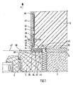
- Fig. 1 is a horizontal section. In Fig. 1 one sees a section of a building wall 2, a section of a built into a window opening of the building wall 2, fixed window frame 4, a section of an openable window sash 6, a section of thermal insulation 8, a plaster finishing strip 10, and an end portion of a plaster layer 12. Mit dem Arrow A is the direction marked away from the building wall 2 to the outside.
- the thermal insulation 8 is mounted on the outside 14 of the building wall 2 and overlaps a piece of the window frame 4. Alternatively, you can see the building wall 2 upwards in Fig. 1 keep thinking so that in this up-continued area the in Fig. 1 left boundary of the building wall 2 represents the soffit surface of the window opening. In this case, the thermal insulation 8 may be mounted on the soffit surface.
- the thermal insulation 8 is typically made of foamed polystyrene or solidified into a plate-like structure mineral fibers.
- Fig. 1 plotted plastic pin 16 is not part of the plaster finishing strip 10, when this is delivered and is later in a first installation phase.
- the function of the pen 16 will be described in more detail below. For the description that follows, let's first think of pen 16 as non-existent.
- the cleaning edge strip has a base region 20, a containment region 22, an expansion strip 24, a cover region 26, a plastering leg 28, a plaster control region 34, a tab 30, and a reinforcement fabric section 32.
- the plaster finishing strip 10 (which for reasons of abbreviation is hereinafter referred to as "strip") is inserted into a gap 36 which extends between the outwardly facing surface 38 of the window frame 4 and the surface 38 facing the end surface 40 of the thermal insulation 8 is located.
- the gap 36 need not have a (measured horizontally) height H, which corresponds to the measured in the same direction height of the introduced into the gap 36 portion of the strip 10. If the height H of the gap 36 is less than the height of said part of the strip 10, this part of the strip 10 is forced into the gap 36 for installation; the thermal insulation 8 is yielding enough to allow this. If the height H of the gap 36 is greater than the said height of the part of the strip 10, this part of the strip 10 is installed so that it rests against the surface 38 of the window frame 4, so that a residual gap to the boundary 40 of the thermal insulation 8 remains ,
- the base portion 20 of the strip 10 has in the illustrated cross-section substantially the configuration of an angle profile. Assuming the coverage area 26 to the base area 20, the base area 20 has a channel-like profile.
- the locking portion 22 has a substantially wall-like configuration.
- the Einputzschenkel 28 projects in the direction of the surface 38 away from the rest of the strip 10 and lies in the drawn installed state against the left in Fig. 1 pointing boundary surface 42 of the insulation 8 at.
- the plaster control region 34 extends substantially at 135 ° relative to the plaster leg 28 and substantially at 135 ° relative to the base wall 43 of the base region 20, which extends parallel to the outer surface 38 of the window frame 4.
- the Einperr Council 22 goes to his in Fig. 1 left end integrally into the free end of Putzend Schemes 34 via.
- the cleaning end region 34 is understood in the present application as part of the base region 20.
- the integral material transition between the end of the locking portion 22 and the end of the cleaning end portion 34 is made with a thin material thickness. Adjacent to this material range of thin material thickness goes in Fig. 1 right end of the tab 30 integrally over into the left end portion of the locking portion 22.
- Am in Fig. 1 right end is the lock-in area 22 behind a corresponding projection 44 locked at the right - bottom end of the base portion 20. If you take the tab 30, starting from the in Fig.
- the expansion strip 24 creates a secure seal of the gap 36, which also contributes later changes in the height H of the gap 36 (eg, by shrinkage or movements of the window frame 4 under wind or by slamming the sash 6) elastic as it.
- the sealing effect is maintained by the continuing expansion tendency of the expansion strip 24 as it were with a certain bias.
- the bar 10 is connected to the thermal insulation 8 and thereby fixed in position.
- the Arm michsgewebeabites 32 lies along the boundary surface 42 of the thermal insulation 8. Partially overlapping herewith is another Arm michsgewebeabêt 46. Both Arm michsgewebeabitese 32 and 46 are spatulated by means not shown putty to the boundary surface 42. After hardening of the filler, the plaster layer 12 is applied.
- a reinforced fixation of the strip 10 to the insulation 8 can be achieved that the pin 16 (in reality, several pins 16 along the length of the bar 10 distributed) through an opening in Einputzschenkel 28 is pushed through into the thermal insulation 8. After hardening of the spatula, but preferably before applying the plaster layer 12, the pin 16 can either be pulled out to the left or almost completely pushed into the heat insulation 8 to the right so that it is no longer visible in finished plaster layer 12.
- the coverage area 26 causes the in-built state (ie after removal of the Einperr Schemes 22) of the in Fig. 1 left end face of the Expansion strip 24 only part of - measured in the direction of the height H of the gap 36 - height of the expansion strip 24 is visible.
- the apparent height of the expansion strip 24 naturally depends on how much the expansion strip 24 has expanded.
- a protective film 46 which is temporarily glued to the surface of the tab 30 directed outwards and provided there with an adhesive layer, can be seen.
- a gutter profiling 48 can be seen on the cleaning end region 34 and on a subsequent part of the height of the plastering leg 28 in order to provide increased adhesion for the plaster layer 12 there.
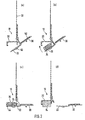
- FIG. 2 Several stages of the manufacture of the strip 10 are illustrated (where compared to Fig. 1 left and right are reversed).
- Sub-figure (a) shows the state after extrusion of the fuselage strip 10 and after applying an adhesive surface 50 on the tab 30, an adhesive strip 52 on the Einperr Society 22 and the welding of Arm michodersgewebeabitess 32.
- the sub-figure (b) shows a later phase, After the compressed expansion strip 24 has been placed on the base region 20 facing surface of the Einperr Schemes 22.
- the subfigure (c) shows a turn later phase in which the Einperr Scheme 22 has been pivoted together with the tab 30 in the clockwise direction and has been locked in the projection 44 with the base portion 20.
- the strip 10 is delivered and installed at a construction site, as in Fig. 1 drawn.
- the adhesive strip 52 helps to temporarily fix the strip 10 to the outer surface 38 of the window frame 4 so that the filling can be applied more conveniently.
- the adhesive strip 52 is just dimensioned so that the Einperr Scheme 22 can be pulled out in the plastered state of the strip 10 without difficulty.
- the sub-figure (d) illustrates the final state after the Einperr Scheme 22 has been pulled out by means of the tab 30 and an expansion of the Expansiosstsammlungs 24 has taken place.
- the locking portion 22 may have a groove-like cross-section.
- the latching projection 44 would then be in the installed state a distance away from the outer surface 38 of the window frame 4, as well as the other end of the Einperr Schemes 22 (there either integral material transition or second locking). This alternative embodiment is particularly suitable when the containment area 22 is to be brought into the release state before the bar 10 is installed.
- Fig. 3 shows a plaster finishing strip 10, which differs from the plaster finishing strip 10 in some points Fig. 1 and Fig. 2 is trained. Analogous components are given the same reference numerals as in Fig. 1 and Fig. 2 designated. Compared to Fig. 1 are at Fig. 3 reversed right and left. Building wall 2, thermal insulation 8, window frame 4 and plaster layer 12 are not drawn, although the drawn state with expanded expansion strip 24 results only in the finished installed state of the plaster finishing strip 10.
- the embodiment of the plaster finishing strip 10 according to Fig. 3 differs essentially from the embodiment of the plaster finishing strip 10 according to Fig. 1 and Fig. 2 by the following:
- the plaster-limiting region 34 extends essentially at right angles to the plastering-in limb 28.
- a flexible protective lip 53 which has been produced by coextrusion with the hull of the plaster-finishing strip 10, is present on the plaster-cutting region 34.
- the Einperr Council 22 is a flat material strip of a material which differs from the material of the hull of the plaster finishing strip 10. In the illustrated embodiment is it is a flat strip of a nonwoven material. In the illustrated embodiment, the nonwoven material, located on a plastic carrier film 54, was adhered to the fuselage plaster molding 10, while the expansion strip 24 was in the trough-shaped installation space between the two side walls 51 and the base wall 43 of the base portion 20 in the compressed state. Left in Fig. 3 the bond between the carrier film 54 and the base region 20 was on the end region of the in Fig. 3 left, angled leg 56 of the base area 20. Right in Fig. 3 was the bond with a surface 58, which is - roughly speaking - in the space between the right side wall 51 and the protective lip 52.
- a first possibility is a severing of the carrier foil 54 just to the left of the expansion strip 24 and just to the right of the expansion strip 24.
- the two wedge-shaped spaces between (a) the leg 56 of the left side wall 51 and (b) the right side wall 51 and the area of Fuselage cleaning plaster 10 at the transition between the Einputzschenkel 28 and the Putzbegrenzungsschenkel 34 allows a comfortable attachment of a knife and comfortable pulling the knife along the plaster finishing strip 10. Therefore, you can see in Fig. 3 short lateral ends of the carrier film 54, which remain after cutting at the Einperr Scheme 22.
- the carrier film 54 was and is glued in the region of the expansion strip 24 both with the expansion strip 24 and with the nonwoven material.
- a second possibility is to solve the two lateral bonds, namely at the end of the leg 56 and on the surface 58, z. B. by pulling away the edges of the carrier film 54 of said mating surfaces and "hanging" the wegholden edges on the expansion strip 24 and the nonwoven material of the Einperr Colours 22.
- the Wegziehbarkeit the edges of the carrier film 54 can be facilitated if there is an unprepared area which one can reach under the finger.
- Perforation lines on the left and / or to the right of the expansion strip 24 are also a possibility that facilitate the transfer of the strip of flat material in the release state. This applies to the removal of the plaster bordering strip 10 and for then-snagging on the plaster finishing strip 10.
- the combination of several options is possible, for. B. Pulling off a wiring right in Fig. 3 and perforation line left in Fig. 3 ,
Landscapes
- Engineering & Computer Science (AREA)
- Architecture (AREA)
- Civil Engineering (AREA)
- Structural Engineering (AREA)
- Mechanical Engineering (AREA)
- Building Environments (AREA)
- Special Wing (AREA)
- Door And Window Frames Mounted To Openings (AREA)
- Cleaning Implements For Floors, Carpets, Furniture, Walls, And The Like (AREA)
Claims (15)
- Procédé d'insertion d'une baguette de finition de crépi (10) pour une couche de crépi (12) sur une isolation thermique (8) d'un bâtiment, la baguette de finition de crépi (10) comprenant une zone de base (20), qui contient une bande de dilatation (24) avec une capacité de dilatation retardée, et une zone de blocage (22), qui, dans l'état de blocage, empêche la dilatation de la bande de dilatation (24), caractérisé(a) en ce qu'un utilisateur de la baguette de finition de crépi (10) amène la zone de blocage (22) dans un état de libération permettant à la bande de dilatation (24) de se dilater ;(b) en ce que, après (a), la baguette de finition de crépi (10) est insérée, avec sa bande de dilatation (24), dans une fente (36) entre un châssis de fenêtre (4) ou un châssis de porte monté préalablement et une isolation thermique (8) installée préalablement, de telle sorte que le côté de libération de la bande de dilatation (24) est orienté vers le châssis de fenêtre (4) ou le châssis de porte ;(c) et en ce que la baguette de finition de crépi (10) est fixé en position dans l'état monté grâce à un raccordement avec l'isolation thermique (8).
- Procédé selon la revendication 1, caractérisé en ce que la zone de base (20) de la baguette de finition de crépi (10) présente une section transversale en forme de goulotte.
- Procédé selon la revendication 1 ou 2, caractérisé en ce que la bande de dilatation (24) de la baguette de finition de crépi (10) est une bande en mousse capable de se dilater de manière retardée.
- Procédé selon l'une des revendications 1 à 3, caractérisé en ce que la baguette de finition de crépi (10) comprend un montant de crépi (28) qui est intégré dans la couche de crépi (12).
- Procédé selon la revendication 4, caractérisé en ce que le montant de crépi (28) comprend un profilé en forme de goulotte (46) augmentant l'adhérence de la couche de crépi (12).
- Procédé selon l'une des revendications 1 à 5, caractérisé en ce que, sur la baguette de finition de crépi (10), est fixée une section de toile armée (32) qui s'étend, lorsque la baguette de finition de crépi (12) est montée, le long d'une surface de l'isolation thermique (8) et qui est reliée avec celle-ci à l'aide par un enduit.
- Procédé selon l'une des revendications 1 à 6, caractérisé en ce que la zone de blocage (22) de la baguette de finition de crépi (10) passe, à une extrémité, lorsqu'elle est vue en coupe transversale, intégralement à la zone de base (20), et à l'autre extrémité, est emboîtée avec une complémentarité de forme avec la zone de base (20).
- Procédé selon l'une des revendications 1 à 7, caractérisé en ce que l'état de libération est obtenu en séparant la zone de blocage (22) de la baguette de finition de crépi (10).
- Procédé selon l'une des revendications 1 à 8, caractérisé en ce que la zone de blocage (22) comprend une patte (30) et en ce que, pour obtenir l'état de libération, une liaison de matière intégrale est séparée entre la zone de blocage (22) et la zone de base (20) en pivotant la patte (30).
- Procédé selon l'une des revendications 1 à 9, caractérisé en ce que la baguette de finition de crépi (10) comprend une zone de recouvrement (26) ou une lèvre de protection flexible (53) sur le côté de la bande de dilatation (24) orienté en direction d'un observateur lorsque la baguette de finition de crépi (10) est montée.
- Procédé selon l'une des revendications 1 à 10, caractérisé en ce que la baguette de finition de crépi (10) comprend une saillie écartée dans
l'état de livraison, et en ce que la baguette de finition de crépi (10) est insérée, après compression élastique de la saillie, dans la fente (36) avec sa bande de dilatation (24). - Procédé selon l'une des revendications 1 à 11, caractérisé en ce que, avant l'insertion de la baguette de finition de crépi (10) avec sa bande de dilatation (24) dans la fente (36), du mastic est appliqué sur le côté du montant de crépi (28) orienté vers l'isolation thermique (8) ou sur le côté de la zone de base (20) orienté vers l'isolation thermique (8).
- Procédé selon l'une des revendications 4 à 12, caractérisé en ce que des tiges de fixation (16) sont insérées dans des ouvertures dans le montant de crépi (28) de la baguette de finition de crépi (10) à travers l'isolation thermique (8).
- Procédé selon l'une des revendications 1 à 13, caractérisé en ce que la zone de blocage (22) de la baguette de finition de crépi (10) comprend une bande en matériau plat qui est fixée, dans l'état de blocage, sur la baguette de finition de crépi (10), la bande de matériau plat étant constituée d'un matériau non tissé ou d'un film plastique ou de papier, la bande de matériau plat étant fixée au reste de la baguette de finition de crépi (10) par soudure, collage ou blocage.
- Procédé selon l'une des revendications 1 à 14, caractérisé en ce que la bande de dilatation dilatée (24) de la baguette de finition de crépi (10) s'appuie contre le châssis de la fenêtre (4) ou de la porte ou contre la zone de blocage (22) libérée, restant entièrement ou partiellement sur la baguette de finition de crépi (10).
Priority Applications (1)
| Application Number | Priority Date | Filing Date | Title |
|---|---|---|---|
| PL10186069T PL2281971T3 (pl) | 2005-12-02 | 2006-12-01 | Sposób montażu listwy tynkarskiej zakończeniowej do warstwy tynku na izolacji cieplnej budynku |
Applications Claiming Priority (2)
| Application Number | Priority Date | Filing Date | Title |
|---|---|---|---|
| DE102005057778A DE102005057778A1 (de) | 2005-12-02 | 2005-12-02 | Putzabschlussleiste für eine Putzschicht auf einer Wärmedämmung |
| EP06024935.6A EP1793061B1 (fr) | 2005-12-02 | 2006-12-01 | Baguette de bord pour une couche d'enduit sur un élément d'isolation thermique |
Related Parent Applications (2)
| Application Number | Title | Priority Date | Filing Date |
|---|---|---|---|
| EP06024935.6 Division | 2006-12-01 | ||
| EP06024935.6A Division-Into EP1793061B1 (fr) | 2005-12-02 | 2006-12-01 | Baguette de bord pour une couche d'enduit sur un élément d'isolation thermique |
Publications (3)
| Publication Number | Publication Date |
|---|---|
| EP2281971A2 EP2281971A2 (fr) | 2011-02-09 |
| EP2281971A3 EP2281971A3 (fr) | 2011-03-23 |
| EP2281971B1 true EP2281971B1 (fr) | 2013-05-01 |
Family
ID=37888404
Family Applications (2)
| Application Number | Title | Priority Date | Filing Date |
|---|---|---|---|
| EP06024935.6A Active EP1793061B1 (fr) | 2005-12-02 | 2006-12-01 | Baguette de bord pour une couche d'enduit sur un élément d'isolation thermique |
| EP10186069.0A Active EP2281971B1 (fr) | 2005-12-02 | 2006-12-01 | Baguette de bord pour une couche d'enduit sur un élément d'isolation thermique |
Family Applications Before (1)
| Application Number | Title | Priority Date | Filing Date |
|---|---|---|---|
| EP06024935.6A Active EP1793061B1 (fr) | 2005-12-02 | 2006-12-01 | Baguette de bord pour une couche d'enduit sur un élément d'isolation thermique |
Country Status (4)
| Country | Link |
|---|---|
| EP (2) | EP1793061B1 (fr) |
| DE (1) | DE102005057778A1 (fr) |
| HU (1) | HUE026445T2 (fr) |
| PL (2) | PL2281971T3 (fr) |
Families Citing this family (19)
| Publication number | Priority date | Publication date | Assignee | Title |
|---|---|---|---|---|
| DE102007048311B4 (de) * | 2007-10-09 | 2022-08-11 | August Braun | Anputzleiste für den Übergang zwischen einem Fensterrahmen oder Türrahmen und einer Wärmedämmung |
| AT10453U1 (de) * | 2008-02-22 | 2009-03-15 | Peter Kassmannhuber | Laibungsanschlussprofil für an putz angrenzende bauteile |
| DE102008036656A1 (de) * | 2008-08-06 | 2010-02-25 | August Braun | Kunststoff-Leiste |
| DE102009034445A1 (de) * | 2009-07-23 | 2011-01-27 | August Braun | Einteilige Abdicht- oder Anputzleiste |
| CN101775846A (zh) * | 2009-12-21 | 2010-07-14 | 吴淑环 | 一种墙体门窗洞口构造 |
| DE102011006223A1 (de) * | 2011-03-28 | 2012-10-04 | August Braun | Anputzleiste sowie Bauwerksecke mit Anputzleiste |
| DE102012223268A1 (de) * | 2012-12-14 | 2014-06-18 | Protektorwerk Florenz Maisch Gmbh & Co. Kg | Laibungsanschlussprofil |
| CN103556903B (zh) * | 2013-11-25 | 2015-08-19 | 哈尔滨森鹰窗业股份有限公司 | 一种被动式窗口安装结构 |
| DE102016110665A1 (de) | 2016-06-09 | 2017-12-14 | Odenwald-Chemie Gmbh | Verbundelement |
| AT15354U1 (de) * | 2016-08-08 | 2017-07-15 | Christian Mick Mag | Anschlussprofilleiste |
| CN107558869A (zh) * | 2017-09-14 | 2018-01-09 | 中国建筑局(集团)有限公司 | 一种窗边海绵保温收边结构、连接构造及其施工方法 |
| DE102018105610A1 (de) * | 2018-03-12 | 2019-09-12 | August Braun | Anputzleiste zur Anordnung an einem Gebäude-Übergang sowie Gebäude-Übergang damit |
| DE102019007280A1 (de) * | 2019-10-11 | 2021-04-15 | Soltkahn AG | Fensterverbund und Verfahren zum Einbau des Fensterverbundes |
| DE102020100248B3 (de) | 2020-01-08 | 2021-07-01 | August Braun | Auflageschere zum Durchtrennen einer Anputzleiste und zum automatischen Erstellen eines Dichtbandüberstands |
| DE102021100706A1 (de) | 2021-01-14 | 2022-07-14 | Ejot Baubefestigungen Gmbh | Anputzleiste und Verfahren zur Herstellung derselben |
| DE102021102672A1 (de) | 2021-02-04 | 2022-08-04 | Ejot Baubefestigungen Gmbh | Anputzleiste |
| DE102023105542A1 (de) * | 2023-03-07 | 2024-09-12 | Protektorwerk Florenz Maisch Gmbh & Co. Kg | Anputzdichtleiste |
| AT526956B1 (de) | 2023-10-06 | 2024-09-15 | Christian Mick Mag | Anputzdichtleiste |
| EP4541996A1 (fr) * | 2023-10-17 | 2025-04-23 | Braun, Magdalena | Baguette de crépissage |
Citations (2)
| Publication number | Priority date | Publication date | Assignee | Title |
|---|---|---|---|---|
| DE4439075A1 (de) * | 1994-11-02 | 1996-05-09 | Maisch F Protektorwerk | Abschlußleiste zum Abdichten eines Rahmenteils gegenüber einer Laibung |
| EP1582685A2 (fr) * | 2004-03-30 | 2005-10-05 | August Braun | Profilé pour joindre une couche d'enduit à un châssis de fenêtre ou similaire avec une partie de base et une partie de jonction |
Family Cites Families (10)
| Publication number | Priority date | Publication date | Assignee | Title |
|---|---|---|---|---|
| DE9110813U1 (de) * | 1991-08-31 | 1992-12-24 | Irbit Research + Consulting Ag, Freiburg/Fribourg | Dichtleiste |
| DE19700107B4 (de) * | 1997-01-03 | 2012-01-26 | August Braun | Expansionsfähige Leiste für den Übergang zwischen einem Fensterstock, Türstock oder dergleichen und einer anschließenden Putzschicht |
| DE19911199A1 (de) * | 1998-04-03 | 1999-10-14 | Exte Extrudertechnik Gmbh | Leiste zur Anordnung zwischen einem Fensterrahmen und einer zugeordneten Laibung |
| DE19950130A1 (de) * | 1999-10-18 | 2001-06-13 | August Braun | Eine an einem Fensterrahmen oder Türrahmen anbringbare Leiste |
| DE29922461U1 (de) * | 1999-12-22 | 2000-03-02 | Menke Kunststoffe GmbH & Co. KG, 59581 Warstein | Einrichtung zur Abdichtung eines Fensterrahmens |
| DE10023697A1 (de) * | 2000-05-16 | 2001-11-29 | Konrad Lehrhuber | Profilleiste zum Abdichten einer Bewegungsfuge zwischen einem Bauteil und einer Putzschicht |
| PL364713A1 (en) * | 2001-03-11 | 2004-12-13 | Vkr Holding A/S | System and methods for sealing to components such as building components, in particular windows, doors and similar building elements |
| DE20317871U1 (de) * | 2003-11-19 | 2004-03-04 | Roma Rolladensysteme Gmbh | Rollladenanordnung |
| AT7692U1 (de) * | 2004-06-04 | 2005-07-25 | Peter Kassmannhuber | Anschlussprofil für eine putzschicht an die führungsschiene eines rollladens |
| DE102007048311B4 (de) * | 2007-10-09 | 2022-08-11 | August Braun | Anputzleiste für den Übergang zwischen einem Fensterrahmen oder Türrahmen und einer Wärmedämmung |
-
2005
- 2005-12-02 DE DE102005057778A patent/DE102005057778A1/de not_active Withdrawn
-
2006
- 2006-12-01 PL PL10186069T patent/PL2281971T3/pl unknown
- 2006-12-01 EP EP06024935.6A patent/EP1793061B1/fr active Active
- 2006-12-01 EP EP10186069.0A patent/EP2281971B1/fr active Active
- 2006-12-01 PL PL06024935T patent/PL1793061T3/pl unknown
- 2006-12-01 HU HUE06024935A patent/HUE026445T2/en unknown
Patent Citations (2)
| Publication number | Priority date | Publication date | Assignee | Title |
|---|---|---|---|---|
| DE4439075A1 (de) * | 1994-11-02 | 1996-05-09 | Maisch F Protektorwerk | Abschlußleiste zum Abdichten eines Rahmenteils gegenüber einer Laibung |
| EP1582685A2 (fr) * | 2004-03-30 | 2005-10-05 | August Braun | Profilé pour joindre une couche d'enduit à un châssis de fenêtre ou similaire avec une partie de base et une partie de jonction |
Also Published As
| Publication number | Publication date |
|---|---|
| EP2281971A2 (fr) | 2011-02-09 |
| PL2281971T3 (pl) | 2013-09-30 |
| EP1793061A3 (fr) | 2008-02-20 |
| EP1793061A2 (fr) | 2007-06-06 |
| EP2281971A3 (fr) | 2011-03-23 |
| EP1793061B1 (fr) | 2015-08-12 |
| DE102005057778A1 (de) | 2007-06-06 |
| HUE026445T2 (en) | 2016-05-30 |
| PL1793061T3 (pl) | 2015-12-31 |
Similar Documents
| Publication | Publication Date | Title |
|---|---|---|
| EP2281971B1 (fr) | Baguette de bord pour une couche d'enduit sur un élément d'isolation thermique | |
| EP0628121B1 (fr) | Bande de crepissage et de protection pour chassis de fenetre, batis de porte ou analogue pour la jonction avec le crepi | |
| EP2093368B1 (fr) | Profilé de raccordement d'intrados pour composants limitrophes d'un enduit | |
| DE9110813U1 (de) | Dichtleiste | |
| EP0801189B1 (fr) | Profilé de raccord pour ouvertures de portes et fenêtres | |
| WO2001088303A1 (fr) | Profile | |
| EP3663498B1 (fr) | Baguette de recouvrement | |
| DE20008712U1 (de) | Profilleiste zum Abdichten einer Bewegungsfuge zwischen einem Bauteil und einer Putzschicht | |
| EP2048314B1 (fr) | Combinaison d'un isolation, un élément d'un bâtiment et une bande de crépissage pour le passage entre un cadre de fenêtre ou un cadre de porte et une isolation thermique | |
| EP1627982B1 (fr) | Profilé de jonction | |
| EP2492429B3 (fr) | Bande de crépissage ainsi qu'angles de construction dotés d'une bande de crépissage | |
| EP0278364B1 (fr) | Dispositif pour le recouvrement d'ouvertures de portes et de fenêtres dans les bâtiments | |
| DE202008006053U1 (de) | Anschlussprofil, insbesondere Putzanschlussprofil | |
| EP3540144A1 (fr) | Bande pour crépi destinée à être agencée sur une transition de bâtiment ainsi que transition de bâtiment associée | |
| EP2762668B1 (fr) | Profil de raccordement | |
| EP1674649B1 (fr) | Profilé de raccord à deux pièces pour éléments de construction voisins d'un crépi | |
| EP3330471B1 (fr) | Baguette de recouvrement destinée à être appliquée sur un composant ainsi que procédé d'application de ladite baguette de recouvrement sur un composant | |
| EP2270304B1 (fr) | Profilé d'enfichage et/ou d'introduction | |
| DE8702045U1 (de) | Vorrichtung zum Abdecken von Fenster- oder Türöffnungen von Gebäuden | |
| EP1707728B1 (fr) | Profilé pour raccorder un panneau d'habillage, notamment un panneau d'habillage de tableau de fenêtre, à un élément de construction, notamment un cadre de porte et de fenêtre ou un rail de volet roulant | |
| DE102017107350A1 (de) | Putzabschlussleiste | |
| EP4446551B1 (fr) | Profilé de raccordement pour composants adjacents sur un enduit | |
| DE202007009911U1 (de) | Dichtungsanordnung | |
| EP4339393B1 (fr) | Baguette de crépissage et jonction de bâtiment | |
| EP3653805B1 (fr) | Profil de raccordement |
Legal Events
| Date | Code | Title | Description |
|---|---|---|---|
| PUAI | Public reference made under article 153(3) epc to a published international application that has entered the european phase |
Free format text: ORIGINAL CODE: 0009012 |
|
| AC | Divisional application: reference to earlier application |
Ref document number: 1793061 Country of ref document: EP Kind code of ref document: P |
|
| AK | Designated contracting states |
Kind code of ref document: A2 Designated state(s): AT BE BG CH CY CZ DE DK EE ES FI FR GB GR HU IE IS IT LI LT LU LV MC NL PL PT RO SE SI SK TR |
|
| AX | Request for extension of the european patent |
Extension state: AL BA HR MK RS |
|
| PUAL | Search report despatched |
Free format text: ORIGINAL CODE: 0009013 |
|
| AK | Designated contracting states |
Kind code of ref document: A3 Designated state(s): AT BE BG CH CY CZ DE DK EE ES FI FR GB GR HU IE IS IT LI LT LU LV MC NL PL PT RO SE SI SK TR |
|
| AX | Request for extension of the european patent |
Extension state: AL BA HR MK RS |
|
| 17P | Request for examination filed |
Effective date: 20110923 |
|
| 17Q | First examination report despatched |
Effective date: 20111111 |
|
| RIC1 | Information provided on ipc code assigned before grant |
Ipc: E04G 21/30 20060101ALN20120521BHEP Ipc: E04F 13/06 20060101ALI20120521BHEP Ipc: E06B 1/62 20060101AFI20120521BHEP |
|
| RIC1 | Information provided on ipc code assigned before grant |
Ipc: E04G 21/30 20060101ALN20120912BHEP Ipc: E04F 13/06 20060101ALI20120912BHEP Ipc: E06B 1/62 20060101AFI20120912BHEP |
|
| REG | Reference to a national code |
Ref country code: DE Ref legal event code: R079 Ref document number: 502006012809 Country of ref document: DE Free format text: PREVIOUS MAIN CLASS: E04F0013060000 Ipc: E06B0001620000 |
|
| GRAP | Despatch of communication of intention to grant a patent |
Free format text: ORIGINAL CODE: EPIDOSNIGR1 |
|
| RIC1 | Information provided on ipc code assigned before grant |
Ipc: E04F 13/06 20060101ALI20121023BHEP Ipc: E04G 21/30 20060101ALN20121023BHEP Ipc: E06B 1/62 20060101AFI20121023BHEP |
|
| GRAS | Grant fee paid |
Free format text: ORIGINAL CODE: EPIDOSNIGR3 |
|
| GRAA | (expected) grant |
Free format text: ORIGINAL CODE: 0009210 |
|
| AC | Divisional application: reference to earlier application |
Ref document number: 1793061 Country of ref document: EP Kind code of ref document: P |
|
| AK | Designated contracting states |
Kind code of ref document: B1 Designated state(s): AT BE BG CH CY CZ DE DK EE ES FI FR GB GR HU IE IS IT LI LT LU LV MC NL PL PT RO SE SI SK TR |
|
| REG | Reference to a national code |
Ref country code: GB Ref legal event code: FG4D Free format text: NOT ENGLISH |
|
| REG | Reference to a national code |
Ref country code: CH Ref legal event code: EP Ref country code: AT Ref legal event code: REF Ref document number: 610065 Country of ref document: AT Kind code of ref document: T Effective date: 20130515 |
|
| REG | Reference to a national code |
Ref country code: IE Ref legal event code: FG4D Free format text: LANGUAGE OF EP DOCUMENT: GERMAN |
|
| REG | Reference to a national code |
Ref country code: DE Ref legal event code: R096 Ref document number: 502006012809 Country of ref document: DE Effective date: 20130627 |
|
| REG | Reference to a national code |
Ref country code: CH Ref legal event code: NV Representative=s name: BOHEST AG, CH |
|
| REG | Reference to a national code |
Ref country code: NL Ref legal event code: T3 |
|
| REG | Reference to a national code |
Ref country code: PL Ref legal event code: T3 |
|
| REG | Reference to a national code |
Ref country code: LT Ref legal event code: MG4D |
|
| PG25 | Lapsed in a contracting state [announced via postgrant information from national office to epo] |
Ref country code: IS Free format text: LAPSE BECAUSE OF FAILURE TO SUBMIT A TRANSLATION OF THE DESCRIPTION OR TO PAY THE FEE WITHIN THE PRESCRIBED TIME-LIMIT Effective date: 20130901 Ref country code: SE Free format text: LAPSE BECAUSE OF FAILURE TO SUBMIT A TRANSLATION OF THE DESCRIPTION OR TO PAY THE FEE WITHIN THE PRESCRIBED TIME-LIMIT Effective date: 20130501 Ref country code: PT Free format text: LAPSE BECAUSE OF FAILURE TO SUBMIT A TRANSLATION OF THE DESCRIPTION OR TO PAY THE FEE WITHIN THE PRESCRIBED TIME-LIMIT Effective date: 20130902 Ref country code: ES Free format text: LAPSE BECAUSE OF FAILURE TO SUBMIT A TRANSLATION OF THE DESCRIPTION OR TO PAY THE FEE WITHIN THE PRESCRIBED TIME-LIMIT Effective date: 20130812 Ref country code: SI Free format text: LAPSE BECAUSE OF FAILURE TO SUBMIT A TRANSLATION OF THE DESCRIPTION OR TO PAY THE FEE WITHIN THE PRESCRIBED TIME-LIMIT Effective date: 20130501 Ref country code: FI Free format text: LAPSE BECAUSE OF FAILURE TO SUBMIT A TRANSLATION OF THE DESCRIPTION OR TO PAY THE FEE WITHIN THE PRESCRIBED TIME-LIMIT Effective date: 20130501 Ref country code: LT Free format text: LAPSE BECAUSE OF FAILURE TO SUBMIT A TRANSLATION OF THE DESCRIPTION OR TO PAY THE FEE WITHIN THE PRESCRIBED TIME-LIMIT Effective date: 20130501 Ref country code: GR Free format text: LAPSE BECAUSE OF FAILURE TO SUBMIT A TRANSLATION OF THE DESCRIPTION OR TO PAY THE FEE WITHIN THE PRESCRIBED TIME-LIMIT Effective date: 20130802 |
|
| REG | Reference to a national code |
Ref country code: SK Ref legal event code: T3 Ref document number: E 14678 Country of ref document: SK |
|
| PG25 | Lapsed in a contracting state [announced via postgrant information from national office to epo] |
Ref country code: BG Free format text: LAPSE BECAUSE OF FAILURE TO SUBMIT A TRANSLATION OF THE DESCRIPTION OR TO PAY THE FEE WITHIN THE PRESCRIBED TIME-LIMIT Effective date: 20130801 Ref country code: CY Free format text: LAPSE BECAUSE OF FAILURE TO SUBMIT A TRANSLATION OF THE DESCRIPTION OR TO PAY THE FEE WITHIN THE PRESCRIBED TIME-LIMIT Effective date: 20130501 |
|
| PG25 | Lapsed in a contracting state [announced via postgrant information from national office to epo] |
Ref country code: LV Free format text: LAPSE BECAUSE OF FAILURE TO SUBMIT A TRANSLATION OF THE DESCRIPTION OR TO PAY THE FEE WITHIN THE PRESCRIBED TIME-LIMIT Effective date: 20130501 |
|
| PG25 | Lapsed in a contracting state [announced via postgrant information from national office to epo] |
Ref country code: EE Free format text: LAPSE BECAUSE OF FAILURE TO SUBMIT A TRANSLATION OF THE DESCRIPTION OR TO PAY THE FEE WITHIN THE PRESCRIBED TIME-LIMIT Effective date: 20130501 Ref country code: DK Free format text: LAPSE BECAUSE OF FAILURE TO SUBMIT A TRANSLATION OF THE DESCRIPTION OR TO PAY THE FEE WITHIN THE PRESCRIBED TIME-LIMIT Effective date: 20130501 |
|
| PG25 | Lapsed in a contracting state [announced via postgrant information from national office to epo] |
Ref country code: RO Free format text: LAPSE BECAUSE OF FAILURE TO SUBMIT A TRANSLATION OF THE DESCRIPTION OR TO PAY THE FEE WITHIN THE PRESCRIBED TIME-LIMIT Effective date: 20130501 |
|
| PLBE | No opposition filed within time limit |
Free format text: ORIGINAL CODE: 0009261 |
|
| STAA | Information on the status of an ep patent application or granted ep patent |
Free format text: STATUS: NO OPPOSITION FILED WITHIN TIME LIMIT |
|
| 26N | No opposition filed |
Effective date: 20140204 |
|
| REG | Reference to a national code |
Ref country code: HU Ref legal event code: AG4A Ref document number: E018734 Country of ref document: HU |
|
| REG | Reference to a national code |
Ref country code: DE Ref legal event code: R097 Ref document number: 502006012809 Country of ref document: DE Effective date: 20140204 |
|
| REG | Reference to a national code |
Ref country code: CH Ref legal event code: PCAR Free format text: NEW ADDRESS: HOLBEINSTRASSE 36-38, 4051 BASEL (CH) |
|
| GBPC | Gb: european patent ceased through non-payment of renewal fee |
Effective date: 20131201 |
|
| PG25 | Lapsed in a contracting state [announced via postgrant information from national office to epo] |
Ref country code: MC Free format text: LAPSE BECAUSE OF FAILURE TO SUBMIT A TRANSLATION OF THE DESCRIPTION OR TO PAY THE FEE WITHIN THE PRESCRIBED TIME-LIMIT Effective date: 20130501 Ref country code: LU Free format text: LAPSE BECAUSE OF FAILURE TO SUBMIT A TRANSLATION OF THE DESCRIPTION OR TO PAY THE FEE WITHIN THE PRESCRIBED TIME-LIMIT Effective date: 20131201 |
|
| REG | Reference to a national code |
Ref country code: IE Ref legal event code: MM4A |
|
| PG25 | Lapsed in a contracting state [announced via postgrant information from national office to epo] |
Ref country code: IE Free format text: LAPSE BECAUSE OF NON-PAYMENT OF DUE FEES Effective date: 20131201 |
|
| PG25 | Lapsed in a contracting state [announced via postgrant information from national office to epo] |
Ref country code: GB Free format text: LAPSE BECAUSE OF NON-PAYMENT OF DUE FEES Effective date: 20131201 |
|
| PG25 | Lapsed in a contracting state [announced via postgrant information from national office to epo] |
Ref country code: TR Free format text: LAPSE BECAUSE OF FAILURE TO SUBMIT A TRANSLATION OF THE DESCRIPTION OR TO PAY THE FEE WITHIN THE PRESCRIBED TIME-LIMIT Effective date: 20130501 |
|
| REG | Reference to a national code |
Ref country code: FR Ref legal event code: PLFP Year of fee payment: 10 |
|
| PGFP | Annual fee paid to national office [announced via postgrant information from national office to epo] |
Ref country code: SK Payment date: 20151120 Year of fee payment: 10 Ref country code: NL Payment date: 20151221 Year of fee payment: 10 Ref country code: CZ Payment date: 20151120 Year of fee payment: 10 Ref country code: PL Payment date: 20151124 Year of fee payment: 10 Ref country code: BE Payment date: 20151221 Year of fee payment: 10 Ref country code: FR Payment date: 20151218 Year of fee payment: 10 Ref country code: HU Payment date: 20151130 Year of fee payment: 10 |
|
| PGFP | Annual fee paid to national office [announced via postgrant information from national office to epo] |
Ref country code: IT Payment date: 20151222 Year of fee payment: 10 |
|
| PG25 | Lapsed in a contracting state [announced via postgrant information from national office to epo] |
Ref country code: BE Free format text: LAPSE BECAUSE OF NON-PAYMENT OF DUE FEES Effective date: 20161231 |
|
| REG | Reference to a national code |
Ref country code: DE Ref legal event code: R082 Ref document number: 502006012809 Country of ref document: DE Representative=s name: SCHMITT-NILSON SCHRAUD WAIBEL WOHLFROM PATENTA, DE |
|
| PG25 | Lapsed in a contracting state [announced via postgrant information from national office to epo] |
Ref country code: CZ Free format text: LAPSE BECAUSE OF NON-PAYMENT OF DUE FEES Effective date: 20161201 |
|
| REG | Reference to a national code |
Ref country code: NL Ref legal event code: MM Effective date: 20170101 |
|
| REG | Reference to a national code |
Ref country code: SK Ref legal event code: MM4A Ref document number: E 14678 Country of ref document: SK Effective date: 20161201 |
|
| PG25 | Lapsed in a contracting state [announced via postgrant information from national office to epo] |
Ref country code: NL Free format text: LAPSE BECAUSE OF NON-PAYMENT OF DUE FEES Effective date: 20170101 |
|
| REG | Reference to a national code |
Ref country code: FR Ref legal event code: ST Effective date: 20170831 |
|
| REG | Reference to a national code |
Ref country code: DE Ref legal event code: R082 Ref document number: 502006012809 Country of ref document: DE Representative=s name: SCHMITT-NILSON SCHRAUD WAIBEL WOHLFROM PATENTA, DE Ref country code: DE Ref legal event code: R081 Ref document number: 502006012809 Country of ref document: DE Owner name: BRAUN, AUGUST, CZ Free format text: FORMER OWNER: BRAUN, AUGUST, SCHAFFHAUSEN, CH |
|
| PG25 | Lapsed in a contracting state [announced via postgrant information from national office to epo] |
Ref country code: IT Free format text: LAPSE BECAUSE OF NON-PAYMENT OF DUE FEES Effective date: 20161201 Ref country code: FR Free format text: LAPSE BECAUSE OF NON-PAYMENT OF DUE FEES Effective date: 20170102 Ref country code: SK Free format text: LAPSE BECAUSE OF NON-PAYMENT OF DUE FEES Effective date: 20161201 |
|
| PG25 | Lapsed in a contracting state [announced via postgrant information from national office to epo] |
Ref country code: HU Free format text: LAPSE BECAUSE OF NON-PAYMENT OF DUE FEES Effective date: 20161202 |
|
| REG | Reference to a national code |
Ref country code: CH Ref legal event code: PCOW Free format text: NEW ADDRESS: CESKE VRBNE 23940, 30711 CESKE BUDEJOVICE (CZ) Ref country code: CH Ref legal event code: PCOW Free format text: NEW ADDRESS: CESKE VRBNE 2390, 37011 CESKE BUDEJOVICE (CZ) |
|
| REG | Reference to a national code |
Ref country code: BE Ref legal event code: MM Effective date: 20161231 |
|
| PG25 | Lapsed in a contracting state [announced via postgrant information from national office to epo] |
Ref country code: PL Free format text: LAPSE BECAUSE OF NON-PAYMENT OF DUE FEES Effective date: 20161201 |
|
| PGFP | Annual fee paid to national office [announced via postgrant information from national office to epo] |
Ref country code: AT Payment date: 20181213 Year of fee payment: 13 |
|
| PGFP | Annual fee paid to national office [announced via postgrant information from national office to epo] |
Ref country code: CH Payment date: 20181219 Year of fee payment: 13 |
|
| REG | Reference to a national code |
Ref country code: CH Ref legal event code: PL |
|
| REG | Reference to a national code |
Ref country code: AT Ref legal event code: MM01 Ref document number: 610065 Country of ref document: AT Kind code of ref document: T Effective date: 20191201 |
|
| PG25 | Lapsed in a contracting state [announced via postgrant information from national office to epo] |
Ref country code: CH Free format text: LAPSE BECAUSE OF NON-PAYMENT OF DUE FEES Effective date: 20191231 Ref country code: LI Free format text: LAPSE BECAUSE OF NON-PAYMENT OF DUE FEES Effective date: 20191231 Ref country code: AT Free format text: LAPSE BECAUSE OF NON-PAYMENT OF DUE FEES Effective date: 20191201 |
|
| REG | Reference to a national code |
Ref country code: DE Ref legal event code: R081 Ref document number: 502006012809 Country of ref document: DE Owner name: BRAUN, MAGDALENA, CH Free format text: FORMER OWNER: BRAUN, AUGUST, CESKE BUDEJOVICE, CZ |
|
| P01 | Opt-out of the competence of the unified patent court (upc) registered |
Effective date: 20230527 |
|
| PGFP | Annual fee paid to national office [announced via postgrant information from national office to epo] |
Ref country code: DE Payment date: 20250226 Year of fee payment: 19 |