EP2048353A2 - Dispositif d'alimentation en carburant pour un véhicule automobile - Google Patents
Dispositif d'alimentation en carburant pour un véhicule automobile Download PDFInfo
- Publication number
- EP2048353A2 EP2048353A2 EP08105472A EP08105472A EP2048353A2 EP 2048353 A2 EP2048353 A2 EP 2048353A2 EP 08105472 A EP08105472 A EP 08105472A EP 08105472 A EP08105472 A EP 08105472A EP 2048353 A2 EP2048353 A2 EP 2048353A2
- Authority
- EP
- European Patent Office
- Prior art keywords
- fuel
- supply device
- chamber
- fuel supply
- activated carbon
- Prior art date
- Legal status (The legal status is an assumption and is not a legal conclusion. Google has not performed a legal analysis and makes no representation as to the accuracy of the status listed.)
- Withdrawn
Links
Images

Classifications
-
- F—MECHANICAL ENGINEERING; LIGHTING; HEATING; WEAPONS; BLASTING
- F02—COMBUSTION ENGINES; HOT-GAS OR COMBUSTION-PRODUCT ENGINE PLANTS
- F02M—SUPPLYING COMBUSTION ENGINES IN GENERAL WITH COMBUSTIBLE MIXTURES OR CONSTITUENTS THEREOF
- F02M37/00—Apparatus or systems for feeding liquid fuel from storage containers to carburettors or fuel-injection apparatus; Arrangements for purifying liquid fuel specially adapted for, or arranged on, internal-combustion engines
- F02M37/20—Apparatus or systems for feeding liquid fuel from storage containers to carburettors or fuel-injection apparatus; Arrangements for purifying liquid fuel specially adapted for, or arranged on, internal-combustion engines characterised by means for preventing vapour lock
-
- F—MECHANICAL ENGINEERING; LIGHTING; HEATING; WEAPONS; BLASTING
- F02—COMBUSTION ENGINES; HOT-GAS OR COMBUSTION-PRODUCT ENGINE PLANTS
- F02M—SUPPLYING COMBUSTION ENGINES IN GENERAL WITH COMBUSTIBLE MIXTURES OR CONSTITUENTS THEREOF
- F02M37/00—Apparatus or systems for feeding liquid fuel from storage containers to carburettors or fuel-injection apparatus; Arrangements for purifying liquid fuel specially adapted for, or arranged on, internal-combustion engines
- F02M37/04—Feeding by means of driven pumps
- F02M37/08—Feeding by means of driven pumps electrically driven
- F02M37/10—Feeding by means of driven pumps electrically driven submerged in fuel, e.g. in reservoir
- F02M37/106—Feeding by means of driven pumps electrically driven submerged in fuel, e.g. in reservoir the pump being installed in a sub-tank
Definitions
- the invention relates to a fuel supply device for a motor vehicle with a disposed in a fuel tank fuel delivery unit for conveying fuel from the fuel tank and with a venting of the fuel tank, with a arranged in the fuel tank surge pot and a fuel from the surge pot sucking fuel pump of the fuel delivery unit, and with at least one Chamber connected to a vent line for separating fuel from the venting device.
- Such fuel supply devices have a plurality of different functional assemblies mounted in or on the fuel tank, such as the venting device and the fuel delivery unit, and are known in practice.
- the swirl pot of the fuel delivery unit is usually biased against the bottom of the fuel tank and receives the fuel pump, which promotes fuel from the swirl pot to the engine of the motor vehicle.
- the venting device has an operating vent with vent lines led into corner regions of the fuel tank and a refueling vent with a vent line guided up to a switch-off point. Chambers of the venting device are usually mounted in the upper region of the fuel tank.
- An activated carbon filter arranged outside the fuel tank allows a pressure equalization of the fuel tank with the environment.
- a disadvantage of the known fuel supply device is that the various functional assemblies require a high design complexity and a complex assembly in or on the fuel tank.
- the invention is based on the problem, a fuel supply device of the type mentioned in such a way that it is particularly simple in design and to assemble.
- venting device and swirl pot of the fuel delivery unit Through the structural unit of the functional assemblies venting device and swirl pot of the fuel delivery unit, the venting device and the swirl pot can be preassembled outside the fuel tank. Subsequently, the structural unit can be easily mounted in the fuel tank. As a result, the assembly of the fuel supply device according to the invention is particularly simple.
- the chamber of the venting device could for example be screwed or glued to the swirl pot.
- the structural unit of swirl pot and chamber of the venting designed according to an advantageous embodiment of the invention is particularly compact, when the swirl pot and the at least one chamber of the venting device are arranged within a common pot-shaped housing. This design contributes to the particularly simple assembly of the structural unit in the fuel tank.
- the structural complexity of the structural unit of swirl pot and chamber of the venting device can be kept particularly low according to an advantageous embodiment of the invention, when a cup-shaped housing walls of the swirl pot and the at least one chamber forms.
- the fuel supply device contributes, if a delivery chamber is arranged with a fine filter in the pot-shaped housing and if the delivery chamber has a connection with the fuel pump and a flow line and if the pressure within the delivery chamber is limited by a pressure regulator.
- a reliable filling of the swirl pot can be ensured at any time according to another advantageous embodiment of the invention, when the pressure regulator opens into the swirl pot.
- This design also ensures the return of too much pumped fuel into the swirl pot with very little construction effort.
- the activated carbon filter is arranged in the common cup-shaped housing of the chamber of the venting device and the swirl pot.
- the fuel supply device is particularly compact when a refueling vent and an operating vent of the venting device each having a connected to inside the fuel tank vent lines associated chamber and when both chambers and a charcoal filter receiving chamber are arranged in the pot-shaped housing and when the charcoal filter receiving chamber is connected to the environment.
- leak diagnostic pumps are often used which detect leaks by generating a pressure differential between the interior of the fuel tank and the environment.
- a contact of the leak diagnosis pump with fuel vapors can be kept particularly low according to an advantageous embodiment of the invention, when the activated charcoal filter receiving chamber is connected to a leak diagnosis pump for detecting a leak in the fuel tank.
- the activated carbon filter is usually regenerated by gases are sucked off the activated carbon filter by the internal combustion engine of the motor vehicle.
- damage to the fuel tank due to faulty regeneration can be avoided if a tank protection valve is arranged between the chambers of the operating ventilation and the refueling ventilation and the chamber receiving the activated carbon filter.
- the tank protection valve prevents a negative pressure in the fuel tank during regeneration of the activated carbon filter.
- Wetting of the activated carbon filter with fuel from the chambers of the operating ventilation and the refueling ventilation can be kept particularly low according to another advantageous embodiment of the invention, when the chambers of the operating ventilation and the refueling vent each having a float / roll-over valve.
- the float / roll-over valve closes at a rollover of the fuel tank having motor vehicle or when exceeding a maximum level in the chamber of the operating vent or the refueling vent the connection to the activated carbon filter receiving chamber.
- the float / roll-over valves are seen from the activated carbon filter from behind the tank protection valve.
- the control of the ventilation of the fuel tank is particularly simple according to another advantageous embodiment of the invention, when a regenerating line connecting the activated carbon filter with the environment can be shut off by a valve.
- the valve is switched electromagnetically.
- valve of the regeneration line and the tank protection valve are designed as a common multi-way valve.
- a common multi-way valve is particularly suitable an electromagnetically switchable 3/3-way valve, which switches ventilation paths in the intended operating conditions.
- fuel accumulated in the fueling vent and service vent chambers could drain directly into the baffle.
- a reliable emptying of the chambers of the venting device can be easily ensured when a suction jet pump is provided for the extraction of accumulated in the chambers of the venting fuel and for direct promotion in the swirl pot. This ensures that as little fuel as possible can accumulate in the chambers at any time.
- the height of the fuel supply device according to the invention can be kept particularly low when the fuel pump lying with a horizontally aligned shaft between a pump stage and an electric motor is arranged.
- FIG. 1 shows a fuel tank 1 with a fuel supply device 2 arranged therein for an internal combustion engine 3 of a motor vehicle.
- the fuel tank 1 has a flange 5 sealingly inserted into a mounting opening 4 of the fuel tank 1.
- a fuel delivery unit 6, a vent 7 and an activated carbon filter 8 are arranged in the fuel tank 1.
- the fuel delivery unit 6 and the venting device 7 have a common pot-shaped housing 9.
- the cup-shaped housing 9 has a swirl pot 10 of the fuel delivery unit 6 for collecting fuel and chambers 11, 12 of the venting device 7.
- a chamber 13 for the activated carbon filter 8 is arranged in the common cup-shaped housing 9.
- the cup-shaped housing 9 is biased against the bottom of the fuel tank 1.
- the fuel delivery unit 6 delivers fuel from the surge pot 10 via a riser 14 into a delivery chamber 15.
- the delivery chamber 15 is connected via a feed line 16 to the internal combustion engine 3 and has a fine filter 17th on. Too much subsidized fuel is returned to the surge pot 10 via a pressure regulator 18.
- the flow line 16 is guided by the flange 5.
- the venting device 7 has an operating vent 19 with a guided into the corner regions of the fuel tank 1 vent line 20 and a refueling vent 21 with a guided up to a designated shutdown of the fuel tank 1 vent line 22.
- the vent lines 20, 22 are each connected to one of the chambers 11, 12 of the venting device 7.
- the chambers 11, 12 of the venting device 7 also each have one of a float / roll-over valve 23, 24 controlled connection 25, 26 with the activated carbon filter 8 having chamber 13.
- a tank protection valve 27 is arranged in the compounds 25, 26 of the chambers 11, 12 of the venting device 7 with the activated carbon filter 8 receiving chamber 13 .
- the tank protection valve 27 prevents damage to the fuel tank 1 in the event of faulty regeneration of the activated carbon filter 8.
- the chambers 11, 12 of the venting device 7 each have their own connections 28, 29 to the fuel delivery unit 6. Through these connections 28, 29 fuel is sucked out of the chambers 11, 12 and conveyed into the swirl pot 10. Furthermore, the fuel delivery unit 6 has one of a fuel pump 30 with fuel supplied as a propellant ejector 31.
- the ejector 31 delivers fuel from the fuel tank 1 in the swirl pot 10.
- the fuel pump sucks 30 via a pre-filter 32 fuel from the swirl pot 10 and promotes this in the delivery chamber 15.
- the activated carbon filter 8 having chamber 13 is connected via a diagnostic line 33 with a leak diagnostic pump 34.
- the leak diagnosis pump 34 is capable of a pressure difference between the interior of the fuel tank 1 and the environment to produce to check the tightness of the fuel tank 1.
- the leak diagnosis pump 34 is arranged on the outside of the flange 5 for this purpose.
- the chamber 13 having the activated carbon filter 8 is connected via a regeneration line 35 to an intake tract 36 of the internal combustion engine 3.
- An electromagnetic valve 37 arranged in the regeneration line 35 is switched via control electronics 38 as a function of the intended venting state.
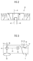
- FIG. 2 schematically shows a designed as a 3/3-way valve multi-way valve 39 as a tank protection valve 27 and disposed in the regeneration line 35 valve 37 from FIG. 1 ,
- the multi-way valve 39 has a port 40 for connection to the in FIG. 1 illustrated chambers 11, 12 of the venting device 7, a port 41 for the regeneration 35 and a leading to the activated carbon filter 8 port 42.
- the multi-way valve 39 allows depending on its position, the pressure equalization of the fuel tank 1 with the environment, the regeneration of the activated carbon filter 8 and the protection of the fuel tank 1 from damage by negative pressure.
- FIG. 3 schematically shows a portion of the fuel delivery unit 6 from FIG. 1 with a driven by an electric motor 43 pump stage 44 of the fuel pump 30. It can be seen that the fuel pump 30 is disposed horizontally, with a horizontal shaft 45 between the electric motor 43 and pump stage 44. Between the pump stage 44 and in the delivery chamber 15 from FIG. 1 leading riser 14, the fuel pump 30 has a branch 46 to the sucking from the fuel tank 1 suction jet pump 31 and to a fuel from the chambers 11, 12 of the venting device 7 sucking suction jet pump 47th
Landscapes
- Engineering & Computer Science (AREA)
- Chemical & Material Sciences (AREA)
- Combustion & Propulsion (AREA)
- Mechanical Engineering (AREA)
- General Engineering & Computer Science (AREA)
- Cooling, Air Intake And Gas Exhaust, And Fuel Tank Arrangements In Propulsion Units (AREA)
Applications Claiming Priority (1)
| Application Number | Priority Date | Filing Date | Title |
|---|---|---|---|
| DE200710048372 DE102007048372A1 (de) | 2007-10-09 | 2007-10-09 | Kraftstoffversorgungseinrichtung für ein Kraftfahrzeug |
Publications (2)
| Publication Number | Publication Date |
|---|---|
| EP2048353A2 true EP2048353A2 (fr) | 2009-04-15 |
| EP2048353A3 EP2048353A3 (fr) | 2014-01-22 |
Family
ID=40120315
Family Applications (1)
| Application Number | Title | Priority Date | Filing Date |
|---|---|---|---|
| EP08105472.8A Withdrawn EP2048353A3 (fr) | 2007-10-09 | 2008-10-01 | Dispositif d'alimentation en carburant pour un véhicule automobile |
Country Status (2)
| Country | Link |
|---|---|
| EP (1) | EP2048353A3 (fr) |
| DE (1) | DE102007048372A1 (fr) |
Family Cites Families (8)
| Publication number | Priority date | Publication date | Assignee | Title |
|---|---|---|---|---|
| US5456235A (en) * | 1994-12-06 | 1995-10-10 | Carter Automotive Company, Inc. | Fuel system |
| DE19501352B4 (de) * | 1995-01-18 | 2006-02-16 | Ti Automotive (Neuss) Gmbh | Brennstoffördereinrichtung mit Strahlpumpenanordnung |
| DE19802078B4 (de) * | 1997-02-20 | 2011-12-29 | Volkswagen Ag | Kraftfahrzeugtank |
| DE19930926A1 (de) * | 1998-07-06 | 2000-05-04 | Alfmeier Praezision Ag | Tanksystem für Kraftfahrzeuge |
| DE10028985A1 (de) * | 2000-06-16 | 2002-01-03 | Mannesmann Vdo Ag | Kraftstoff-Förder- und Lüftungssystem |
| DE10318844A1 (de) * | 2003-04-25 | 2004-11-11 | Siemens Ag | Kraftstoffbehälter |
| DE102005031430A1 (de) * | 2005-07-04 | 2007-01-11 | Siemens Ag | Vorrichtung zum Fördern von Kraftstoff aus einem Kraftstoffbehälter |
| DE102005043888A1 (de) * | 2005-09-14 | 2007-03-29 | Siemens Ag | Entlüftungseinrichtung für einen Kraftstoffbehälter |
-
2007
- 2007-10-09 DE DE200710048372 patent/DE102007048372A1/de not_active Withdrawn
-
2008
- 2008-10-01 EP EP08105472.8A patent/EP2048353A3/fr not_active Withdrawn
Also Published As
| Publication number | Publication date |
|---|---|
| EP2048353A3 (fr) | 2014-01-22 |
| DE102007048372A1 (de) | 2009-04-23 |
Similar Documents
| Publication | Publication Date | Title |
|---|---|---|
| EP2652306B1 (fr) | Moteur a combustion interne avec nettoyage de reservoir de carburant améliorée | |
| EP1301367A1 (fr) | Unite d'alimentation en carburant | |
| DE19645382A1 (de) | Tankanlage für ein Fahrzeug mit Verbrennungsmotor | |
| DE10143819B4 (de) | Kraftstoffmodul | |
| DE102004022564A1 (de) | Kraftstoffversorgungseinrichtung für ein Kraftfahrzeug | |
| DE102004024466A1 (de) | Kraftstoffmodul | |
| DE102011105891A1 (de) | Vorrichtung zum druckabhängigen Öffnen einer Ansaugöffnung | |
| WO2007085536A1 (fr) | Unité de transport | |
| EP1492683B1 (fr) | Unite de refoulement de carburant pour automobile | |
| EP1504943B1 (fr) | Réservoir de carburant à conteneur de dissipation de bulles pour automobile | |
| EP1484211B1 (fr) | reservoir à carburant avec des reservoirs internes | |
| DE102009014436B4 (de) | Fördereinrichtung zur Förderung einer wässrigen Flüssigkeit | |
| DE102007039861A1 (de) | Kraftstoffsatteltank und Verfahren zum Betrieb eines Kraftstofffördersystems in einem Kraftstoffsatteltank | |
| EP2738031B1 (fr) | Système de réservoir pour un véhicule automobile | |
| DE102010063207A1 (de) | Filteranordnung und Fördermodul mit einer solchen Filteranordnung | |
| DE19843318C5 (de) | Kraftstofffördereinheit | |
| DE102014222632A1 (de) | Aktives Spülpumpensystemmodul für ein Verdampfungs-Emissionssteuersystem | |
| EP2048353A2 (fr) | Dispositif d'alimentation en carburant pour un véhicule automobile | |
| EP3516201B1 (fr) | Procédé de déshumidification d'un consommable ainsi que dispositif de déshumidification | |
| EP1831536A1 (fr) | Dispositif de transport destine au transport de carburant a partir d'un reservoir de carburant | |
| WO2008006827A1 (fr) | Réservoir de carburant pour un véhicule | |
| EP1022457B1 (fr) | Dispositif d'alimentation en carburant | |
| DE102006032099A1 (de) | Fördereinheit zum Fördern von Kraftstoff | |
| EP2159407A1 (fr) | Installation d'alimentation en carburant pour un véhicule automobile | |
| DE102015004716A1 (de) | Vorrichtung zum Überprüfen der Dichtheit eines Tanks sowie Baukastensystem für mehrere Bauvarianten einer solchen Vorrichtung |
Legal Events
| Date | Code | Title | Description |
|---|---|---|---|
| PUAI | Public reference made under article 153(3) epc to a published international application that has entered the european phase |
Free format text: ORIGINAL CODE: 0009012 |
|
| AK | Designated contracting states |
Kind code of ref document: A2 Designated state(s): AT BE BG CH CY CZ DE DK EE ES FI FR GB GR HR HU IE IS IT LI LT LU LV MC MT NL NO PL PT RO SE SI SK TR |
|
| AX | Request for extension of the european patent |
Extension state: AL BA MK RS |
|
| PUAL | Search report despatched |
Free format text: ORIGINAL CODE: 0009013 |
|
| AK | Designated contracting states |
Kind code of ref document: A3 Designated state(s): AT BE BG CH CY CZ DE DK EE ES FI FR GB GR HR HU IE IS IT LI LT LU LV MC MT NL NO PL PT RO SE SI SK TR |
|
| AX | Request for extension of the european patent |
Extension state: AL BA MK RS |
|
| RIC1 | Information provided on ipc code assigned before grant |
Ipc: F02M 37/10 20060101AFI20131218BHEP |
|
| AKY | No designation fees paid | ||
| REG | Reference to a national code |
Ref country code: DE Ref legal event code: R108 |
|
| STAA | Information on the status of an ep patent application or granted ep patent |
Free format text: STATUS: THE APPLICATION IS DEEMED TO BE WITHDRAWN |
|
| REG | Reference to a national code |
Ref country code: DE Ref legal event code: R108 Effective date: 20140924 |
|
| 18D | Application deemed to be withdrawn |
Effective date: 20140501 |