EP2049749B1 - Revêtement de sol et procédé de pose - Google Patents
Revêtement de sol et procédé de pose Download PDFInfo
- Publication number
- EP2049749B1 EP2049749B1 EP07801228A EP07801228A EP2049749B1 EP 2049749 B1 EP2049749 B1 EP 2049749B1 EP 07801228 A EP07801228 A EP 07801228A EP 07801228 A EP07801228 A EP 07801228A EP 2049749 B1 EP2049749 B1 EP 2049749B1
- Authority
- EP
- European Patent Office
- Prior art keywords
- groove
- floor covering
- spring
- head
- covering according
- Prior art date
- Legal status (The legal status is an assumption and is not a legal conclusion. Google has not performed a legal analysis and makes no representation as to the accuracy of the status listed.)
- Active
Links
Images


Classifications
-
- E—FIXED CONSTRUCTIONS
- E04—BUILDING
- E04F—FINISHING WORK ON BUILDINGS, e.g. STAIRS, FLOORS
- E04F15/00—Flooring
- E04F15/02—Flooring or floor layers composed of a number of similar elements
-
- E—FIXED CONSTRUCTIONS
- E04—BUILDING
- E04F—FINISHING WORK ON BUILDINGS, e.g. STAIRS, FLOORS
- E04F15/00—Flooring
- E04F15/02—Flooring or floor layers composed of a number of similar elements
- E04F15/04—Flooring or floor layers composed of a number of similar elements only of wood or with a top layer of wood, e.g. with wooden or metal connecting members
-
- E—FIXED CONSTRUCTIONS
- E04—BUILDING
- E04F—FINISHING WORK ON BUILDINGS, e.g. STAIRS, FLOORS
- E04F2201/00—Joining sheets or plates or panels
- E04F2201/01—Joining sheets, plates or panels with edges in abutting relationship
- E04F2201/0138—Joining sheets, plates or panels with edges in abutting relationship by moving the sheets, plates or panels perpendicular to the main plane
-
- E—FIXED CONSTRUCTIONS
- E04—BUILDING
- E04F—FINISHING WORK ON BUILDINGS, e.g. STAIRS, FLOORS
- E04F2201/00—Joining sheets or plates or panels
- E04F2201/01—Joining sheets, plates or panels with edges in abutting relationship
- E04F2201/0153—Joining sheets, plates or panels with edges in abutting relationship by rotating the sheets, plates or panels around an axis which is parallel to the abutting edges, possibly combined with a sliding movement
-
- E—FIXED CONSTRUCTIONS
- E04—BUILDING
- E04F—FINISHING WORK ON BUILDINGS, e.g. STAIRS, FLOORS
- E04F2201/00—Joining sheets or plates or panels
- E04F2201/01—Joining sheets, plates or panels with edges in abutting relationship
- E04F2201/0169—Joining sheets, plates or panels with edges in abutting relationship by rotating the sheets, plates or panels around an axis which is perpendicular to the abutting edges and parallel to the main plane, possibly combined with a sliding movement
-
- E—FIXED CONSTRUCTIONS
- E04—BUILDING
- E04F—FINISHING WORK ON BUILDINGS, e.g. STAIRS, FLOORS
- E04F2201/00—Joining sheets or plates or panels
- E04F2201/05—Separate connectors or inserts, e.g. pegs, pins, keys or strips
- E04F2201/0523—Separate tongues; Interlocking keys, e.g. joining mouldings of circular, square or rectangular shape
- E04F2201/0541—Separate tongues; Interlocking keys, e.g. joining mouldings of circular, square or rectangular shape adapted to be moved along the joint edge
-
- E—FIXED CONSTRUCTIONS
- E04—BUILDING
- E04F—FINISHING WORK ON BUILDINGS, e.g. STAIRS, FLOORS
- E04F2201/00—Joining sheets or plates or panels
- E04F2201/05—Separate connectors or inserts, e.g. pegs, pins, keys or strips
- E04F2201/0523—Separate tongues; Interlocking keys, e.g. joining mouldings of circular, square or rectangular shape
- E04F2201/0547—Separate tongues; Interlocking keys, e.g. joining mouldings of circular, square or rectangular shape adapted to be moved perpendicular to the joint edge
-
- F—MECHANICAL ENGINEERING; LIGHTING; HEATING; WEAPONS; BLASTING
- F16—ENGINEERING ELEMENTS AND UNITS; GENERAL MEASURES FOR PRODUCING AND MAINTAINING EFFECTIVE FUNCTIONING OF MACHINES OR INSTALLATIONS; THERMAL INSULATION IN GENERAL
- F16B—DEVICES FOR FASTENING OR SECURING CONSTRUCTIONAL ELEMENTS OR MACHINE PARTS TOGETHER, e.g. NAILS, BOLTS, CIRCLIPS, CLAMPS, CLIPS OR WEDGES; JOINTS OR JOINTING
- F16B5/00—Joining sheets or plates, e.g. panels, to one another or to strips or bars parallel to them
- F16B5/0004—Joining sheets, plates or panels in abutting relationship
- F16B5/0032—Joining sheets, plates or panels in abutting relationship by moving the sheets, plates, or panels or the interlocking key parallel to the abutting edge
- F16B5/0044—Joining sheets, plates or panels in abutting relationship by moving the sheets, plates, or panels or the interlocking key parallel to the abutting edge and using interlocking keys of circular, square, rectangular or like shape
-
- Y—GENERAL TAGGING OF NEW TECHNOLOGICAL DEVELOPMENTS; GENERAL TAGGING OF CROSS-SECTIONAL TECHNOLOGIES SPANNING OVER SEVERAL SECTIONS OF THE IPC; TECHNICAL SUBJECTS COVERED BY FORMER USPC CROSS-REFERENCE ART COLLECTIONS [XRACs] AND DIGESTS
- Y10—TECHNICAL SUBJECTS COVERED BY FORMER USPC
- Y10T—TECHNICAL SUBJECTS COVERED BY FORMER US CLASSIFICATION
- Y10T428/00—Stock material or miscellaneous articles
- Y10T428/16—Two dimensionally sectional layer
- Y10T428/163—Next to unitary web or sheet of equal or greater extent
- Y10T428/164—Continuous two dimensionally sectional layer
- Y10T428/167—Cellulosic sections [e.g., parquet floor, etc.]
Definitions
- the invention relates to a floor covering according to the features in the preamble of claim 1. Furthermore, the invention relates to a laying method according to the features in the preamble of claim 24.
- Prefabricated parquet, real wood floors or laminate floors consist of several rows of predominantly rectangular floor panels in their configuration.
- the floor panels on one longitudinal side and one head side have continuous grooves and on the respectively opposite longitudinal side or head side continuous springs, which are adapted to the grooves form-fitting manner.
- the floor panels of two adjacent rows are offset from each other.
- the mechanical locking elements between tongue and groove are first hooked into each other in a longitudinal or head side, so it often causes difficulties to create the positive connection for the other side.
- the floor panels are rotated along their long sides into each other or clicked and then moved laterally, so that the locking strips engage the head sides.
- light hammer blows can be applied from the opposite side of the head with the aid of a pad.
- a similar proposal is the subject of DE 101 38 285 A1 , There it is described that a shock-bridging locking element can be introduced into a designated locking recess by inserting or striking. It is possible to design the tolerances of the blocking element and the locking recess so that the blocking element can be easily or tightly inserted into the locking recess.
- the invention has for its object to improve a floor covering consisting of element panels laying technology. Furthermore, an improved with respect to this property installation method should be shown.
- the invention particularly relates to the mutual, vertical-acting fixation of the head sides of element plates, which are provided on the longitudinal side with a glue-free tongue and groove connection.
- the operating principle is based on the idea that a movable part of the head spring is laterally deflected by the longitudinal insertion process of the head spring into the head groove.
- the displaceable head spring need not be made in one piece, but may be formed from different sections.
- the displacement in the longitudinal direction of the head groove is preferably less than 10 mm and ideally as large as the width of the longitudinal spring of an element plate, ie for example 1.5 to 4 mm.
- the projecting portion of the head spring protruding from the head groove should not protrude beyond the outermost edge of the element panel, that is to say in particular not via a lower locking bar.
- the head spring In the locked position, the head spring is located completely within the head groove and preferably ends flush with the groove bottom of the longitudinal coupling groove.
- the head spring can therefore also be adapted with its front side to the contour of the longitudinal groove base.
- the head spring is preassembled in one of the grooves, if possible not projecting beyond the head-side groove mouth of the groove and thus to a certain extent completely chambered within the groove, wherein only one end of the head spring over the opening in the longitudinal side of the element plate from the groove should project.
- This end may also be referred to as an actuating portion intended to exert a force in the longitudinal direction of the groove on the head spring to at least partially displace it into the corresponding groove of the adjacent element plate and thereby lock the element plates together at the head end.
- the head spring has in the preassembled state, a width which is smaller than the width of the Sperrkanals. If the grooves in the head sides are the same depth, the head spring is maximally as wide as one of the grooves is deep, that is at most half as wide as the barrier channel formed by the grooves. Of course, it is possible to form the grooves in the top sides of different depths. For example, the groove, in which the movable part of the head spring is to engage, for structural reasons, only 50% of the depth of the other groove.
- the main advantage of the floor covering is that the subsequent insertion or insertion of the head spring into the locking channel is eliminated.
- This process of subsequent insertion is not only associated with a separate step, but also requires intuition, since this activity is carried out depending on the position of the fitter over head, or at least very close to the ground.
- the head spring is preassembled in one of the grooves, the above-described steps of inserting or striking the head spring are completely eliminated, whereby the laying speed can be significantly increased.
- the head spring in the preassembled state does not project beyond the head side of the element plate, that is in no way hindered during assembly.
- an element plate which has already been laid in the preceding longitudinal side of one Element plate is pivoted, unlike the solution in the EP 1 650 375 A1 be pivoted downwards without any effort. Aligning the head sides in height does not yet lead to a locking in the region of the locking channel, so that the adjacent panels can also be easily resumed, if this is required for laying technical reasons.
- the fits of the head spring and the grooves are matched to one another such that the axial displacement of the head spring is as smooth as possible. That is, the sliding part of the head spring should indeed be kept within the groove before moving, but still be easily relocated. At the same time a game but should be so small that a vertical displacement of the head side abutting element plates is largely excluded.
- those portions of the head spring which emerge from the first groove and engage in the corresponding groove of the adjacent element plate are provided with a slightly narrower fit than the remaining portions of the head spring, which displaces only in the axial direction become.
- the displaceability may be over the coefficient of friction lowering additives or coatings, which are arranged or applied in the region of the contact surfaces of the components, such. Waxes, oils, etc., to be improved.
- the head spring can be displaced counter to a spring force which causes the head spring to emerge from the end of the groove at a later unlocking, or is again completely received in the groove when viewed from the head side.
- the locking is thus against a spring force, so that the head spring in the locked position is under bias.
- the spring force can be applied by a separate spring element, such as a coil spring or can be achieved by the residual stress of the material used for the head spring itself.
- a manual locking is required, for example, by a fixing clamp is inserted into the longitudinal coupling groove of the element plate.
- a head side is an end face of an element plate to understand.
- the head side is usually the shorter side of the element plate, wherein also square element plates have a head side with top spring and long sides.
- the head spring can accumulate on insertion into the groove on a ramp surface, so that the head spring is displaced laterally in the direction of the corresponding groove.
- a ramp surface may be formed in the element plate or the groove itself by a partial region of the groove bottom or the entire groove base is bevelled in particular.
- the groove depth is varied over the longitudinal extent. If the groove depth increases continuously, the Kopffeder can be effectively designed as a wedge, wherein the groove muzzle facing the longitudinal side during displacement in the axial direction emerges uniformly from the groove and engages in the corresponding groove of the adjacent element plate.
- the ramp surface is in this case a wedge surface.
- the Groove depth is dimensioned so that the head spring in the locked state can not slide out of the corresponding groove out again automatically. Accordingly, the slope of the ramp surface or wedge surface to the maximum displacement, that is tuned to the length of the protruding from the groove end.
- the ramp surface it is also possible to make the ramp surface rounded, so that the ramp surface does not necessarily have to be linear straight. Decisive is the function of the ramp surface, namely, that it serves as a contoured abutment to cause a lateral displacement of the head spring in their longitudinal displacement.
- the run-on surface is part of a wedge body arranged in the groove of the head spring. That is, the head spring is constructed in two parts, wherein the head spring is divided into a wedge body and a push portion. As the thrust portion of that longitudinal portion of the head spring is referred to, which carries the protruding from the groove end. Depending on the arrangement of the ramp surface, it is possible that either the pushing section or the wedge body is at least partially displaced into the corresponding groove.
- the wedge body and the thrust portion may have approximately the same length, so that the ramp surface and thus the region to be displaced of the wedge body or the thrust portion also arranged in the central region of the head side are.
- approximately the middle third of the locking groove is to be locked at least in sections, in particular if the element plate is provided with a chamfer.
- the groove receiving the head tongue has at least one recess in which the ramp surface is formed and in which a cam of the head tongue engages.
- the groove is provided with an additional contouring in the form of a recess for forming a ramp surface.
- This embodiment has manufacturing advantages, since on the one hand, a continuous end-side groove can be produced, in which only the recess still has to be introduced.
- the recess itself is provided in the groove bottom.
- the recess can in particular be produced by a saw cut, so that the recess has the contour of a circular section. This circular section may also be rounded in its transitional regions to the groove base, so that, as it were, a sinusoidal shape of the recess results. This is not least due to manufacturing technology, since during processing, the individual element plates parallel to the saw blade, which is used for introducing the recess, move. If this movement is not absolutely synchronous, blurring occurs in the edge area and thus to rounded transitions.
- the recess is a rectangularly configured pocket which is generated by a milling cutter or even a hole in the groove bottom, wherein the ramp surface of a bore is limited to the edge of the hole, so that in this case in the bore projecting cam comes only selectively with the ramp surface in contact.
- the cam generates the lowest possible frictional resistance. Therefore, it is provided that the at least one cam is narrower than the head spring.
- the cam itself may be wedge-shaped or rounded.
- the decisive factor is that the cam is designed such that it allows sliding on the ramp surface and is not hindered. In this respect, the area of the cam facing the ramp surface should at least partially be oriented in the same direction as the ramp surface.
- the head spring may have a cam at its end projecting beyond the groove. This cam then runs on the corner of the groove or slides along this corner, so that the head spring is moved out of the groove.
- This cam is preferably configured wedge-shaped.
- the head spring itself may be configured to be curled to reduce friction, with its corrugated sides facing the decor side and the underside of the element plate.
- the head spring may have clamping pins, by means of which the head spring is held in a punctiform manner in the groove.
- the clamping pins serve as additional transport safety and have a very small cross-section. They are only intended to give the head spring a firm hold before shifting or snapping.
- the head feather on one of its long sides a chamfer which facilitates the insertion of the head spring into the groove of the adjacent element plate during the locking operation.
- a head spring constructed in two parts with respect to its active constituents has a predetermined breaking point, via which the active components, that is to say the thrust section and the wedge body, are connected to one another. In this way it is ensured that no part of the head spring unintentionally falls out of the groove during transport and assembly.
- the breaking point should of course be destroyed.
- the head spring consists of a resilient plastic and arcuately curved by moving the protruding end into the groove, so that the arcuately curved portion comes into engagement with the adjacent element plate. Even with this configuration, the spring-back of the plastic used causes the head spring completely returns to its original groove, so that the floor covering can be retrofitted easily retrofitted.
- the head spring has two legs connected to one another via a joint, wherein the region of the legs surrounding the joint can be brought into engagement with the corresponding groove of the element plate when the protruding end is displaced into the groove.
- the joint may be a film hinge.
- the floor covering according to the invention can in principle be locked manually on the head side. This means that after laying a panel row by hand and with the help of hand tools, such as. with the help of a Switzerlandisens, on the end of the head spring can be pressed to immerse them completely in the groove and to bridge the butt joint in the region of the Sperrkanals.
- the head-side locking is carried out according to a laying method with the measures of patent claim 24.
- the lock is almost automatically by the creation of a further series of element plates, which bridge the rear impact region of the previously laid element plate row.
- the head sides are only latched when a further element plate engages with the longitudinal sides of the preceding row of panels and pushes with its longitudinal side protruding from the groove end of the head spring into the groove, so that these transversely engages the insertion direction in the opposite groove of the other head side and locks the element plates head side together.
- the head spring is configured so that it is returned to a discharge in the original groove, that is, when the end of the head spring emerges automatically from the groove, this is equivalent to an automatic unlocking when receiving the flooring.
- This is also a decisive advantage over known laying methods, in which the head spring must be removed either by moving the element plates against each other.
- the head spring consists of several parts, which are, however, captively connected to one another via a connecting element.
- the connecting element be over the groove projecting bar, which still projects beyond the insertion of the Kopffeder in the groove on the groove and milled or sawn only in the context of finishing, so that in the groove only not connected parts of the head spring remain. This approach simplifies the handling of the head spring during the manufacturing process.
- Bolt can be moved.
- the head spring should not protrude beyond a decorative or cover layer of the element plate in the unlocked state, i. When viewed from above, it should not be visible so that it does not interfere with the transport and handling of the element panels.
- the material for the head spring may be both a wood material, i. it may be wood or a material containing wood fibers. Metals and metal alloys are just as suitable as composites. The use of bimetallic or mixed plastics is just as possible as the use of materials based on thermoplastic or thermosetting plastics.
- the head spring may in particular consist of a fiber-reinforced plastic with a fiber content of 20% to 60%.
- the inventive concept is applicable to all floor systems in which an upper covering is arranged on a support, such as real wood coverings, laminate, support with painted surfaces as top coat, linoleum, cork on support plates, etc.
- the cover layer may in particular consist of a decorative paper with overlay, which determines the appearance of the element plate.
- the floor covering may thus be a parquet floor, a finished parquet floor, a real wood floor or a laminate floor.
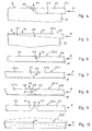
- FIG. 1 shows a floor covering, consisting of a plurality of laid in the composite rectangular panel panels 1.
- the panel panels 1 each have on their head sides 2, 3 and on their long sides 4, 5 locking strips. The locking strips arrive in the mounting position with adjacent panels in a covering with each other in engagement.
- Locking strips 6, 7 on the head sides 2 and 3 of an element plate 1 can be seen in the FIG. 2 , In the FIG. 2 is a vertical section through the head-side joint area between two element plates 1, so that one looks at the connection to the head sides 2, 3.
- the locking strips, not shown, on the longitudinal sides of an element plates 1 can be configured differently than the locking strips 6, 7.
- An element plate 1 consists of a base layer 8 of fiber material, usually of a high- or medium-density fiberboard, wherein the base layer 8 has an upper-side cover layer 9 and a lower-side counter-train 10.
- the cover layer 9 may consist of a decorative paper with an overlay, which determines the appearance of the floor panels 1.
- the so-called overlay or the seal forms a special treated wear layer, which gives the floor panels 1 a high surface durability.
- the counter-pull 10 on the underside of the support layer 8 serves the dimensional stability and the moisture barrier.
- Each element plate 1 has a locking strip 6 (1st locking strip) on the one head side 2 (1st head side) and a locking strip 7 (2nd locking strip) on the opposite side of the head 3 (2nd head side).
- the first locking bar 6 has a downwardly open first dome channel 11 and a downwardly directed end-side 1. Kuppelwulst 12.
- the second locking bar 7 on the opposite 2nd head side 3 of an element plate 1 is arranged on the bottom side and jumps against the support layer. 8 in front.
- the underside 13 of the second locking strip 7 extends in the plane of the underside 14 of the element plate 1.
- the second locking strip 7 has an upwardly open second coupling channel 15 and an upward end-side second coupling bead 16.
- first locking bar 6 and 2nd locking bar 7 engages the first dome bulge 12 in the 2nd dome channel 15 and the 2nd Kuppelwulst 16 in the 1st dome channel 11.
- first locking bar 6 and 2nd locking bar 7 engages the first dome bulge 12 in the 2nd dome channel 15 and the 2nd Kuppelwulst 16 in the 1st dome channel 11.
- grooves 19, 20 are formed, which extend over the entire length of the head sides 2, 3. As based on the FIG. 2 to recognize, correspond to the grooves 19, 20 of the abutting head side 2, 3 and form a barrier channel 21. In this blocking channel 21 a hatched head spring 22 is inserted.
- the grooves 19, 20 in the head sides 2, 3 are provided above the locking strips 6, 7 in the support layer 8.
- FIG. 3 shows a perspective view in the direction of the head side 2 of an element plate 1. From this illustration, it is apparent that the head spring 22 is disposed completely in the preassembled position within the groove 20 and in particular does not protrude beyond the head-side Nutmündung 23. However, the head spring 22 projects with its end 24 in the region of the longitudinal side 5 out of the groove 22. In FIG. 3 is merely exemplified as the head spring 22 is disposed in the groove 20. The operation and possible embodiments of the head spring is described below with reference to FIGS. 4 to 10 explained.
- FIG. 4 shows that the head spring 22 when inserted into the groove 20 in the direction of arrow P runs on a ramp surface 25 in the form of a wedge surface and is thus pivoted in the direction of arrow P1 out of the groove 20 and thereby in a manner not shown with the corresponding Groove 19 of the adjacent element plate 1 engages, as shown in FIG presentation of the FIG. 2 can be seen.
- the special in the embodiment of the FIG. 4 is that the groove 20 does not extend over the entire length of the head side 2, so that the ramp surface 25 is formed directly by the groove bottom.
- FIG. 6 shows a variant with a two-part head spring 22 b, which comprises a push portion 26 and a wedge body 27.
- Push section 26 and wedge body 27 encounter in analogy to the embodiment of FIG. 4 in the region of the wedge surface 25 to each other, so that by displacement of the thrust portion 26 in the direction of the arrow P, the inner end of the thrust portion 26 is pivoted transversely to the direction of the arrow P in the not-shown groove of the other element plate 1.
- the arrow P1 illustrates the pivoting direction.
- FIG. 7 shows a variant of a two-part head spring 22c, in which the ramp surface 25 is mounted with reverse inclination on a wedge body 27a, so that the displacement of the thrust portion 26a in the direction of arrow P causes a displacement of the wedge body 27a in the direction of the arrow P1.
- the locking therefore does not take place via the push section 26a, but via the wedge body 27a.
- FIG. 8 a wedge body 27b of a coupling spring 22d is shown, whose end facing the thrust portion 26b is configured V-shaped.
- V-shaped end engages a form-fitting adapted tip 30 of the thrust portion 26b.
- the V-shaped end is formed by two spring legs 28, 29, which pass through the tip 30 of the push portion 26b when displaced in the direction of the arrow P are pushed apart, so that the one spring leg 28 is pushed transversely to the thrust direction out of the groove 20 and displaced for locking in the groove 20 of the adjacent element plate 1.
- a portion of the tip 30 of the thrust section also engages with the corresponding groove of the adjacent element plate 1.
- FIG. 9 shows a variant of a head spring 22e made of a plastic material.
- the head spring 22e comprises two legs 32, 33 connected to one another via a joint 31.
- the legs 32, 33 are chamfered, so that a V-shaped notch results in the head spring 22e.
- the legs 32, 33 are displaced relative to each other, so that the region of the joint 31 can be pressed into the groove of the adjacent element plate 1 and thus contributes to the vertical locking of the adjacent panels.
- FIG. 10 shows finally an embodiment of a head spring 22f made of an elastic material that can be curved without wedge surfaces and joints exclusively by exerting force in the direction of the longitudinal axis of the coupling spring 22f, so that the arcuate portion engages with the corresponding groove of the adjacent element plate.
- the embodiments of the FIGS. 8 to 10 have the overall advantage that an automatic reset of the head spring in the original groove is possible by a spring effect.
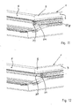
- FIGS. 11 and 12 show the end 24 of a head spring 22g in the unlatched position (FIG. FIG. 11 ) and in the locked position ( FIG. 12 ). From the illustrations, it is clear that the end face 34 of the protruding end 24 of the head spring 22g is adapted to the contour of the longitudinal dome channel 35, that is to say concave in this case. Furthermore, it can be seen that the head spring 22g in the unlocked state does not protrude beyond the decorative or cover layer 9 of the element plate 1, so that the head spring 22g is not visible from above and does not obstruct the obstacle Transport, handling and laying of the element plates 1 is.
- the FIGS. 13 and 14 show a variant of a head spring 22h, which is constructed in three parts.
- a rear part of the head spring 22 h is clawed in the groove flanks of the groove 20, so that it can not shift in the longitudinal direction of the groove 20.
- the rear part may also be referred to as a wedge body 27c.
- the wedge body 27c serves as an abutment for a trapezoidally configured central portion, which acts as a blocking body 36.
- not the longitudinally displaceable thrust section 26c is displaced laterally out of the groove, but only the locking body 36 which is supported both on a wedge surface on the wedge body 27c and on a wedge surface on the thrust section 26c.
- a variant of a head spring 22i which comprises a thrust portion 26d and a sleeve 37 leading the thrust portion 26d.
- the push portion 26d can be displaced against the spring force of a spring 38 within the sleeve 37.
- the spring 38 is supported on a bottom 39 of the sleeve 37 from.
- the sleeve 37 has lateral openings 40 which are arranged so that in the pockets 41 of the thrust portion 26d mounted locking body 42 can be pivoted out of the openings under the influence of a spring force and thereby engage in a manner not shown in a groove of an adjacent element plate to cause a head-side locking of the adjacent element plates.
- This type of head spring 22i can be used as a preassembled unit, in particular for thicker element plates, and permits reliable and reversible locking between the head-side grooves.
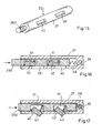
- FIG. 18 a variant of a head spring 22j is shown, which in turn is located in a groove 20 of the element plate 1 and in turn is displaced upon locking two element plates in the direction of the arrow P, thereby emerging from the groove 20 in the direction of the arrow P1.
- there is a parallel displacement of the head spring 22j which is due to two cams 43, 44 is due, which extend in the direction of the groove bottom of the groove 20.
- a first cam 43 is located in the transition region from the middle to the left in the image plane third of the head spring 22j.
- the cam 43 is configured triangular and projects into a recess 45, which is configured in a circular segment.
- the recess 45 has been produced for example by a disc-shaped saw blade which has been inserted into the groove 20.
- the cam 43 is matched to the depth of the recess 45, so that the head spring 22j rests in the unlocked state on the groove bottom.
- her front end 24 is not on the element plate 1 before.
- the second cam 44 which extends into the longitudinal dome channel 35.
- This cam 44 runs on the 90 degree corner in the transition region between the longitudinal dome channel 35 and the end groove 20. Since the displacement is small, this second cam 44 is made shorter or is not so far in the direction of the dome channel 35 before as the cam 43 in the recess provided therefor 45.
- the geometries of the cams 43, 44 may be coordinated so that a parallel displacement of the head spring 22j is possible.
- clamping pins 46 are distributed over the length of the head spring 22j.
- the clamping pins 46 are small protrusions on the top and bottom of the head spring 22j and serve to clamp them in the position shown.
- the embodiment of the FIG. 19 is different from the one of FIG. 18 in that the recess 45a is less deep than in the embodiment of FIG. 18 and that the cam 43a is correspondingly shorter.
- FIG. 20 shows the head spring 22k in the front view.
- the head spring 22k is corrugated toward the top and bottom of the groove 20 so that the contact surfaces of the head spring 22k with the groove 20 are reduced to reduce the friction.
- the clamping pins 46 are arranged both on the upper side and on the underside of the top spring 22 k and hold them within the groove 20.
- the dashed line cam 43a has a width which is smaller than the width of the main body of the head spring 22k, so that the friction between the cam 43a and the ramp surface within the recess 45 is minimized.
Landscapes
- Engineering & Computer Science (AREA)
- Architecture (AREA)
- Civil Engineering (AREA)
- Structural Engineering (AREA)
- Floor Finish (AREA)
Abstract
Claims (24)
- Revêtement de sol constitué d'une pluralité de plaques élémentaires (1) à poser en combinaison, qui possèdent sur leurs côtés frontaux (2, 3) et sur leurs côtés longitudinaux (4, 5) des barrettes de verrouillage (6, 7) qui viennent en engagement mutuel dans la situation de montage avec des plaques élémentaires (1) voisines dans un revêtement, dans lequel des gorges (19, 20) sont prévues dans les côtés frontaux (2, 3), lesdites gorges (19, 20) de deux côtés frontaux (2, 3) en aboutement mutuel étant en alignement et réalisant un canal de blocage (21) pour la réception d'une languette frontale (22, 22a-k), la languette frontale (22, 22a-k) étant montée préalablement dans l'une des gorges (20), caractérisé en ce que la languette frontale (22, 22a-k) dépasse au-delà d'une extrémité, tournée vers le côté longitudinal (5) de la plaque élémentaire (1), de la gorge (20) et est déplaçable, par translation de l'extrémité dépassante (24) de la languette frontale (22, 22a-k) en pénétration dans la gorge (20), partiellement depuis une gorge (20) jusque dans la gorge correspondante (19) de la plaque élémentaire voisine (1).
- Revêtement de sol selon la revendication 1, caractérisé en ce que la languette frontale (22) monte sur une surface d'entrée (25) lors de l'introduction dans la gorge (20).
- Revêtement de sol selon la revendication 2, caractérisé en ce que la surface d'entrée (25) est réalisée dans la gorge (20).
- Revêtement de sol selon la revendication 2 ou 3, caractérisé en ce que la surface d'entrée (25) fait partie d'un corps en coin (27, 27a, 27b, 27c), agencé dans la gorge (20), de la languette frontale (22b, 22c, 22d).
- Revêtement de sol selon l'une des revendications 2 à 4, caractérisé en ce qu'un tronçon de poussée (26, 26b), qui porte l'extrémité (24) dépassant hors de la gorge (20), de la languette frontale (22b, 22d) est déplaçable en engagement d'action avec la surface d'entrée (25) au moins partiellement dans la gorge correspondante (19).
- Revêtement de sol selon la revendication 4, caractérisé en ce que le corps en coin (27a, 27b) est déplaçable en engagement d'action avec un tronçon de poussée (26a, 26b) qui porte l'extrémité (24) de la languette frontale (22c, 22d) dépassant hors de la gorge (20) au moins partiellement dans la gorge correspondante (19).
- Revêtement de sol selon la revendication 4, caractérisé en ce que le tronçon de poussée (26b), qui porte l'extrémité (24) de la languette frontale (22d) dépassant hors de la gorge (20), ou bien le corps en coin (27b) est susceptible d'être écarté, par un engagement d'action réciproque, du côté extrémité en direction de la gorge correspondante (19).
- Revêtement de sol selon la revendication 4, caractérisé en ce qu'un corps de blocage (36) est agencé entre le corps en coin (27c) et le tronçon de poussée (26c), ledit corps de blocage étant déplaçable par déplacement du tronçon de poussée (26c) au moins partiellement dans la gorge correspondante (19).
- Revêtement de sol selon l'une des revendications 4 à 7, caractérisé en ce que le corps en coin (27, 27a, 27b) et un tronçon de poussée (26, 26a, 26b) qui porte l'extrémité (24) dépassant hors de la gorge (20) sont reliés l'un à l'autre via un emplacement de consigne de rupture, l'introduction de la languette frontale (22b-d) ayant lieu avec destruction de l'emplacement de consigne de rupture.
- Revêtement de sol selon la revendication 1, caractérisé en ce que la gorge (20) qui reçoit la languette frontale (22j, 22k) comporte au moins un évidement (45, 45a) dans lequel est réalisée la surface d'entrée (25) et dans lequel s'engage une came (43, 43a) de la languette frontale (22j).
- Revêtement de sol selon la revendication 10, caractérisé en ce que la came (43, 43a, 44) est plus étroite que la languette frontale (22j, 22k).
- Revêtement de sol selon la revendication 10 ou 11, caractérisé en ce que la came (43, 44) est en forme de coin.
- Revêtement de sol selon la revendication 10 ou 11, caractérisé en ce que la came (43a) est arrondie.
- Revêtement de sol selon l'une des revendications 10 à 13, caractérisé en ce que l'évidement (45, 45a) possède un contour en forme d'arc.
- Revêtement de sol selon l'une des revendications 10 à 14, caractérisé en ce que la languette frontale (22j, 22k) comporte une came (44) à son extrémité (24) dépassant au-delà de la gorge (20).
- Revêtement de sol selon l'une des revendications 1 à 15, caractérisé en ce que la languette frontale (22j, 22a) est ondulée, ses côtés ondulés étant tournés vers un côté décor et vers une face inférieure des plaques élémentaires (1).
- Revêtement de sol selon l'une des revendications 1 à 16, caractérisé en ce que la languette frontale (22j, 22a) comporte des tenons de serrage (46), via lesquels la languette frontale (22j, 22k) est retenue dans la gorge (20) avec serrage ponctuel.
- Revêtement de sol selon la revendication 1, caractérisé en ce que la languette frontale (22f) est en un matériau synthétique présentant l'élasticité d'un ressort, la languette frontale (22f) pouvant être incurvée en forme d'arc par translation de l'extrémité (24) en dépassement en pénétration dans la gorge (20), et peut être ici amenée en engagement avec la gorge correspondante (19) de la plaque élémentaire voisine (1).
- Revêtement de sol selon l'une des revendications 1 à 18, caractérisé en ce que la languette frontale (22e) comporte deux branches (32, 33) reliées l'une à l'autre via une articulation (31), la zone des branches (32, 33) qui entoure l'articulation (31) pouvant être amenée en engagement avec la gorge correspondante (19) de la plaque élémentaire voisine (1) par translation de l'extrémité (24) en dépassement en pénétration dans la gorge (20).
- Revêtement de sol selon la revendication 1, caractérisé en ce qu'un tronçon de poussée (26d), qui porte l'extrémité (24) dépassant hors de la gorge (20), de la languette frontale (22i) est guidé dans une douille (37) à mettre en place dans la gorge (20), dans lequel le tronçon de poussée (26d) comprend au moins un corps de blocage (42) chargé par un ressort qui, lors d'une translation du tronçon de poussée (26d) à l'intérieur de la douille (37) est susceptible d'être pivoté sous l'influence de la force du ressort hors d'une ouverture latérale (40) de la douille (37), et déplaçable au moins partiellement dans la gorge correspondante (19).
- Revêtement de sol selon l'une des revendications 1 à 20, caractérisé en ce que le contour d'un côté frontal (34) de l'extrémité (24) en dépassement de la languette frontale (22g) est adapté au contour d'un canal d'accouplement (35) du côté longitudinal.
- Revêtement de sol selon l'une des revendications 1 à 21, caractérisé en ce que la languette frontale (22g) dans l'état non verrouillé ne dépasse pas au-delà d'une couche de décoration ou de couverture (9) de la plaque élémentaire (1).
- Revêtement de sol selon l'une des revendications 1 à 22, caractérisé en ce qu'il s'agit d'un plancher en parquet, d'un plancher en parquet fini, d'un plancher en bois véritable ou d'un plancher en stratifié.
- Procédé de pose pour un revêtement de sol, dans lequel une pluralité de plaques élémentaires (1) à poser en combinaison sont enclenchées les unes avec les autres via des barrettes de verrouillage (6, 7) agencées sur leurs côtés frontaux (2, 3) et sur leurs côtés longitudinaux (4, 5), de sorte que des plaques élémentaires (1) mutuellement voisines viennent en engagement mutuel, et les côtés frontaux (2, 3) sont verrouillés les uns avec les autres par des languettes frontales (22, 22a-k) mises en place dans des gorges en alignement (19, 20), caractérisé en ce que les côtés frontaux (2, 3) sont enclenchés uniquement quand une autre plaque élémentaire (1) parvient en engagement avec son côté longitudinal (4) engagé avec les côtés longitudinaux (5) de la rangée de plaques élémentaires précédente, et pousse ici jusque dans la gorge (20) au moyen de son côté longitudinal (4) une extrémité (24) de la languette frontale (22, 22a-k) qui dépasse hors de la gorge (20), de sorte que celle-ci s'engage transversalement à la direction d'introduction dans la gorge opposée (19) de l'autre côté frontal (2, 3) et verrouille les plaques élémentaires (1) ensemble du côté frontal.
Priority Applications (3)
| Application Number | Priority Date | Filing Date | Title |
|---|---|---|---|
| PL09003663T PL2063045T3 (pl) | 2006-08-10 | 2007-08-10 | Wykładzina podłogowa |
| PL07801228T PL2049749T3 (pl) | 2006-08-10 | 2007-08-10 | Wykładzina podłogowa i sposób układania |
| EP09003663.3A EP2063045B1 (fr) | 2006-08-10 | 2007-08-10 | Revêtement de sol |
Applications Claiming Priority (3)
| Application Number | Priority Date | Filing Date | Title |
|---|---|---|---|
| DE102006037614A DE102006037614B3 (de) | 2006-08-10 | 2006-08-10 | Fußbodenbelag und Verlegeverfahren |
| PCT/DE2007/000584 WO2008017281A1 (fr) | 2006-08-10 | 2007-03-30 | Revêtement de sol et procédé de pose |
| PCT/DE2007/001425 WO2008017301A2 (fr) | 2006-08-10 | 2007-08-10 | Revêtement de sol et procédé de pose |
Related Child Applications (2)
| Application Number | Title | Priority Date | Filing Date |
|---|---|---|---|
| EP09003663.3A Division EP2063045B1 (fr) | 2006-08-10 | 2007-08-10 | Revêtement de sol |
| EP09003663.3 Division-Into | 2009-03-13 |
Publications (2)
| Publication Number | Publication Date |
|---|---|
| EP2049749A2 EP2049749A2 (fr) | 2009-04-22 |
| EP2049749B1 true EP2049749B1 (fr) | 2009-09-09 |
Family
ID=38267650
Family Applications (2)
| Application Number | Title | Priority Date | Filing Date |
|---|---|---|---|
| EP09003663.3A Not-in-force EP2063045B1 (fr) | 2006-08-10 | 2007-08-10 | Revêtement de sol |
| EP07801228A Active EP2049749B1 (fr) | 2006-08-10 | 2007-08-10 | Revêtement de sol et procédé de pose |
Family Applications Before (1)
| Application Number | Title | Priority Date | Filing Date |
|---|---|---|---|
| EP09003663.3A Not-in-force EP2063045B1 (fr) | 2006-08-10 | 2007-08-10 | Revêtement de sol |
Country Status (8)
| Country | Link |
|---|---|
| US (1) | US8302367B2 (fr) |
| EP (2) | EP2063045B1 (fr) |
| CN (1) | CN101490346B (fr) |
| DE (3) | DE102006037614B3 (fr) |
| ES (1) | ES2331669T3 (fr) |
| PL (2) | PL2063045T3 (fr) |
| RU (1) | RU2394137C1 (fr) |
| WO (2) | WO2008017281A1 (fr) |
Cited By (2)
| Publication number | Priority date | Publication date | Assignee | Title |
|---|---|---|---|---|
| US8997430B1 (en) | 2010-04-15 | 2015-04-07 | Spanolux N.V.-Div. Balterio | Floor panel assembly |
| US9206611B2 (en) | 2010-01-14 | 2015-12-08 | Spanolux N.V.—Div. Balterio | Floor panel assembly and floor panel for use therein |
Families Citing this family (133)
| Publication number | Priority date | Publication date | Assignee | Title |
|---|---|---|---|---|
| JP4472355B2 (ja) | 2002-04-03 | 2010-06-02 | ベーリンゲ、イノベイション、アクチボラグ | フロアボード用機械式係止システム |
| US7841144B2 (en) | 2005-03-30 | 2010-11-30 | Valinge Innovation Ab | Mechanical locking system for panels and method of installing same |
| US7454875B2 (en) | 2004-10-22 | 2008-11-25 | Valinge Aluminium Ab | Mechanical locking system for floor panels |
| SE530653C2 (sv) | 2006-01-12 | 2008-07-29 | Vaelinge Innovation Ab | Fuktsäker golvskiva samt golv med ett elastiskt ytskikt omfattande ett dekorativt spår |
| SE533410C2 (sv) | 2006-07-11 | 2010-09-14 | Vaelinge Innovation Ab | Golvpaneler med mekaniska låssystem med en flexibel och förskjutbar tunga samt tunga därför |
| US8689512B2 (en) | 2006-11-15 | 2014-04-08 | Valinge Innovation Ab | Mechanical locking of floor panels with vertical folding |
| US11725394B2 (en) | 2006-11-15 | 2023-08-15 | Välinge Innovation AB | Mechanical locking of floor panels with vertical folding |
| SE531111C2 (sv) * | 2006-12-08 | 2008-12-23 | Vaelinge Innovation Ab | Mekanisk låsning av golvpaneler |
| DE202007019674U1 (de) * | 2007-02-21 | 2015-05-27 | Hamberger Industriewerke Gmbh | Verbindung für plattenförmige Bauelemente |
| DE102007026342B4 (de) * | 2007-06-06 | 2013-11-28 | Laminatepark Gmbh & Co. Kg | Set aus tafelförmigen Paneelen mit bewegbarem Verriegelungselement |
| DE102007063837B3 (de) | 2007-06-06 | 2020-01-23 | Laminatepark Gmbh & Co. Kg | Set aus tafelförmigen Paneelen mit bewegbarem Verriegelungselement |
| WO2009061279A1 (fr) | 2007-11-07 | 2009-05-14 | Välinge Innovation AB | Blocage mécanique de panneaux de sol avec encliquetage sur pliure verticale et procédé d'installation pour relier ces panneaux |
| US8353140B2 (en) | 2007-11-07 | 2013-01-15 | Valinge Innovation Ab | Mechanical locking of floor panels with vertical snap folding |
| DE102008003117B4 (de) * | 2008-01-02 | 2011-01-27 | Flooring Technologies Ltd. | Einrichtung zum Verriegeln zweier Bauplatten |
| DE102008003550B4 (de) | 2008-01-09 | 2009-10-22 | Flooring Technologies Ltd. | Einrichtung und Verfahren zum Verriegeln zweier Bodenpaneele |
| EP2235285B1 (fr) | 2008-01-31 | 2019-06-26 | Välinge Innovation AB | Bloqueur mécanique de panneaux de sol |
| US8505257B2 (en) | 2008-01-31 | 2013-08-13 | Valinge Innovation Ab | Mechanical locking of floor panels |
| CN102066674B (zh) | 2008-05-15 | 2015-06-03 | 瓦林格创新股份有限公司 | 具有通过磁场启动的机械锁定系统的地板镶板及安装镶板的方法 |
| DE102008030281B3 (de) * | 2008-06-30 | 2009-10-29 | Guido Schulte | Verfahren und Vorrichtung zum Einsetzen von Federn in eine Nut |
| DE102008047098B3 (de) * | 2008-09-12 | 2010-04-08 | Guido Schulte | Fußbodenbelag |
| DE102008047099B4 (de) * | 2008-09-12 | 2010-05-12 | Guido Schulte | Fußbodenbelag |
| BE1018627A5 (nl) * | 2009-01-16 | 2011-05-03 | Flooring Ind Ltd Sarl | Vloerpaneel. |
| SG172871A1 (en) * | 2009-01-30 | 2011-08-29 | Vaelinge Innovation Belgium Bvba | Mechanical lockings of floor panels and a tongue blank |
| EP2236694A1 (fr) | 2009-03-25 | 2010-10-06 | Spanolux N.V.- DIV. Balterio | Système de fixation et panneau |
| DE102009034903B3 (de) | 2009-07-27 | 2011-01-20 | Guido Schulte | Belag aus mechanisch miteinander verbindbaren Paneelen |
| DE102009034902B4 (de) | 2009-07-27 | 2015-10-01 | Guido Schulte | Belag aus mechanisch miteinander verbindbaren Paneelen |
| US11725395B2 (en) | 2009-09-04 | 2023-08-15 | Välinge Innovation AB | Resilient floor |
| US8365499B2 (en) | 2009-09-04 | 2013-02-05 | Valinge Innovation Ab | Resilient floor |
| EP2473687B1 (fr) | 2009-09-04 | 2019-04-24 | Välinge Innovation AB | Procédé d'assemblage de lames de parquet souples qui sont équipées d'un système de verrouillage mécanique |
| DE102009041297B4 (de) | 2009-09-15 | 2018-10-11 | Guido Schulte | Belag aus mechanisch miteinander verbindbaren Elementen und ein Verfahren zur Herstellung von Elementen |
| DE102009051430B4 (de) | 2009-10-30 | 2012-08-02 | Guido Schulte | Verfahren zur spanabhebenden Bearbeitung eines Paneels und Vorrichtung zur Durchführung des Verfahrens |
| EP3702549B1 (fr) | 2010-01-12 | 2023-05-10 | Välinge Innovation AB | Jeu de panneaux de sol |
| US8234830B2 (en) | 2010-02-04 | 2012-08-07 | Välinge Innovations AB | Mechanical locking system for floor panels |
| BR112012018285B1 (pt) | 2010-02-04 | 2020-02-18 | Välinge Innovation AB | Conjunto de painéis de piso |
| KR101245963B1 (ko) * | 2010-03-02 | 2013-03-21 | 오광석 | 바닥재 및 이에 이용되는 회전체 |
| BE1019331A5 (nl) | 2010-05-10 | 2012-06-05 | Flooring Ind Ltd Sarl | Vloerpaneel en werkwijzen voor het vervaardigen van vloerpanelen. |
| DE102010022290B4 (de) | 2010-05-31 | 2016-08-18 | Guido Schulte | Fußboden-, Wand- oder Deckenelement |
| EP2657428B1 (fr) * | 2010-10-20 | 2018-08-08 | Kronoplus Technical AG | Revêtement de surface comprenant des panneaux stratifiés et un élément de verrouillage étranger |
| DE202010015754U1 (de) | 2010-11-23 | 2011-01-20 | Akzenta Paneele + Profile Gmbh | Fußbodenpaneel mit weichelastischer Nutzschicht |
| US8806832B2 (en) | 2011-03-18 | 2014-08-19 | Inotec Global Limited | Vertical joint system and associated surface covering system |
| UA109938C2 (uk) | 2011-05-06 | 2015-10-26 | Механічна фіксуюча система для будівельних панелей | |
| FR2975718B1 (fr) * | 2011-05-25 | 2015-01-02 | Inovame | Lame de structure plane de parement ou de parquet |
| FR2975717A1 (fr) * | 2011-09-22 | 2012-11-30 | Epi Flooring | Insert dissociable de blocage vertical entre deux lames d'une structure plane de parement ou de parquet. |
| FR2975716A1 (fr) * | 2011-05-25 | 2012-11-30 | Espace Production Internationale | Systeme de blocage entre deux lames d'une structure plane de parement ou de parquet. |
| UA114715C2 (uk) | 2011-07-05 | 2017-07-25 | Сералок Інновейшн Аб | Механічна фіксація панелей настилу підлоги до язичка з нанесеним шаром клею |
| US9725912B2 (en) | 2011-07-11 | 2017-08-08 | Ceraloc Innovation Ab | Mechanical locking system for floor panels |
| US8650826B2 (en) | 2011-07-19 | 2014-02-18 | Valinge Flooring Technology Ab | Mechanical locking system for floor panels |
| DE102012102339A1 (de) | 2011-07-29 | 2013-01-31 | Hamberger Industriewerke Gmbh | Verbindung für elastische oder plattenförmige Bauelemente, Profilschieber und Fußbodenbelag |
| DE102012105793A1 (de) | 2011-07-29 | 2013-01-31 | Hamberger Industriewerke Gmbh | Verbindung für elastische oder plattenförmige Bauelemente und Fußbodenbelag |
| DE102011052335B4 (de) | 2011-08-01 | 2015-09-17 | Guido Schulte | Belag aus mechanisch miteinander verbindbaren Paneelen und Verfahren zur Herstellung solcher Paneele |
| US8857126B2 (en) | 2011-08-15 | 2014-10-14 | Valinge Flooring Technology Ab | Mechanical locking system for floor panels |
| US8769905B2 (en) | 2011-08-15 | 2014-07-08 | Valinge Flooring Technology Ab | Mechanical locking system for floor panels |
| RU2611090C2 (ru) * | 2011-08-15 | 2017-02-21 | Сералок Инновейшн Аб | Механическая блокировочная система для панелей пола |
| US8763340B2 (en) | 2011-08-15 | 2014-07-01 | Valinge Flooring Technology Ab | Mechanical locking system for floor panels |
| CN102383572A (zh) * | 2011-08-25 | 2012-03-21 | 德尔国际家居股份有限公司 | 一种插入式锁扣地板 |
| WO2013029320A1 (fr) * | 2011-08-29 | 2013-03-07 | Yao Xizhi | Structure de plancher assemblable avec élément de connexion |
| US9216541B2 (en) | 2012-04-04 | 2015-12-22 | Valinge Innovation Ab | Method for producing a mechanical locking system for building panels |
| US8596013B2 (en) | 2012-04-04 | 2013-12-03 | Valinge Innovation Ab | Building panel with a mechanical locking system |
| RS60954B1 (sr) * | 2012-06-19 | 2020-11-30 | Vaelinge Innovation Ab | Sistem mehaničkog zaključavanja podnih dasaka |
| WO2014033628A1 (fr) | 2012-08-27 | 2014-03-06 | Pergo (Europe) Ab | Panneau |
| AU2013348454C1 (en) | 2012-11-22 | 2017-11-09 | Ceraloc Innovation Ab | Mechanical locking system for floor panels |
| US9194134B2 (en) | 2013-03-08 | 2015-11-24 | Valinge Innovation Ab | Building panels provided with a mechanical locking system |
| CN103266743B (zh) * | 2013-06-03 | 2015-05-13 | 德尔国际家居股份有限公司 | 一种插入式锁扣地板 |
| HUE060779T2 (hu) | 2013-06-27 | 2023-04-28 | Vaelinge Innovation Ab | Mechanikus rögzítõrendszerrel ellátott építõpanel |
| US10060139B2 (en) | 2013-07-09 | 2018-08-28 | Ceraloc Innovation Ab | Mechanical locking system for floor panels |
| EP3024998B1 (fr) * | 2013-07-24 | 2018-07-11 | Pantev, Gueorgui | Mécanisme auto-bloquant et panneautage |
| US9726210B2 (en) | 2013-09-16 | 2017-08-08 | Valinge Innovation Ab | Assembled product and a method of assembling the product |
| EP3039195B1 (fr) | 2013-09-16 | 2019-01-02 | Best Woods Inc. | Joints de raccordement de revêtement de surface |
| DK3047160T3 (en) | 2013-09-16 | 2019-04-08 | Vaelinge Innovation Ab | TOTAL FURNITURE PRODUCT |
| RU2662745C2 (ru) | 2013-10-25 | 2018-07-30 | Сералок Инновейшн Аб | Механическая замковая система для панелей пола |
| DE102013113109A1 (de) | 2013-11-27 | 2015-06-11 | Guido Schulte | Fußbodendiele |
| DE102013113130B4 (de) | 2013-11-27 | 2022-01-27 | Välinge Innovation AB | Verfahren zur Herstellung einer Fußbodendiele |
| DE102013113125A1 (de) | 2013-11-27 | 2015-05-28 | Guido Schulte | Fußboden-, Wand- oder Deckenpaneel und Verfahren zu dessen Herstellung |
| US9714672B2 (en) | 2014-01-10 | 2017-07-25 | Valinge Innovation Ab | Panels comprising a mechanical locking device and an assembled product comprising the panels |
| PL3092123T3 (pl) | 2014-01-10 | 2023-11-27 | Välinge Innovation AB | Panel na bazie włókien drzewnych z warstwą powierzchniową |
| CA2933681C (fr) | 2014-01-10 | 2021-10-19 | Valinge Innovation Ab | Panneau de meuble |
| US9260870B2 (en) | 2014-03-24 | 2016-02-16 | Ivc N.V. | Set of mutually lockable panels |
| WO2015144726A1 (fr) | 2014-03-24 | 2015-10-01 | Ivc N.V. | Ensemble de panneaux mutuellement verrouillables |
| CN106460901B (zh) | 2014-05-09 | 2020-02-04 | 瓦林格创新股份有限公司 | 用于建筑镶板的机械锁定系统 |
| HRP20251107T1 (hr) | 2014-05-12 | 2025-11-07 | Välinge Innovation AB | Metoda proizvodnje furniranog elementa |
| US10246883B2 (en) | 2014-05-14 | 2019-04-02 | Valinge Innovation Ab | Building panel with a mechanical locking system |
| KR102386246B1 (ko) | 2014-05-14 | 2022-04-12 | 뵈린게 이노베이션 에이비이 | 기계식 록킹 시스템이 구비된 빌딩 패널 |
| CN107027318A (zh) | 2014-07-11 | 2017-08-08 | 瓦林格创新股份有限公司 | 具有滑动件的面板 |
| DE102014112529A1 (de) | 2014-09-01 | 2016-03-03 | Guido Schulte | Mechanische Verbindung für Paneele und Verfahren zur Montage einer Verriegelungsfeder in einem Paneel |
| DE102014112527A1 (de) | 2014-09-01 | 2016-03-03 | Guido Schulte | Mechanische Verbindung für Paneele und Verfahren zur Montage einer Verriegelungsfeder in einem Paneel |
| CN107002411B (zh) | 2014-11-27 | 2020-06-16 | 瓦林格创新股份有限公司 | 用于地板镶板的机械锁定系统 |
| BR112017012422B1 (pt) | 2014-12-19 | 2022-11-08 | Vãlinge Innovation Ab | Conjunto de painéis compreendendo um dispositivo de travamento mecânico |
| EP3245353B1 (fr) * | 2015-01-16 | 2020-04-29 | Flooring Industries Limited, SARL | Panneau de plancher pour la formation d'un revêtement de sol |
| DE102015102671B4 (de) | 2015-02-25 | 2024-10-31 | Guido Schulte | Paneele mit einer mechanischen Verbindung für diese Paneele, Verfahren zur Montage einer Verriegelungsfeder in einem Paneel und Verfahren zum Verbinden von Paneelen mit einer mechanischen Verbindung |
| DE202015101541U1 (de) | 2015-03-19 | 2015-05-05 | Guido Schulte | Mechanische Verbindung für Paneele |
| EP3285620A4 (fr) | 2015-04-21 | 2018-11-14 | Välinge Innovation AB | Panneau à coulisse |
| MY185635A (en) | 2015-04-30 | 2021-05-27 | Valinge Innovation Ab | Panel with a fastening device |
| EP3310580A4 (fr) | 2015-06-16 | 2019-02-13 | Välinge Innovation AB | Procédé de formation d'élément de surface ou de panneau de construction, et élément de surface et panneau de construction |
| UA125554C2 (uk) | 2015-09-22 | 2022-04-20 | Велінге Інновейшн Аб | Панелі, що містять механічний фіксуючий пристрій, і зібраний виріб, що містить панелі |
| LT3384165T (lt) | 2015-12-03 | 2021-11-10 | Välinge Innovation AB | Plokščių su mechaniniu fiksavimo įrenginiu rinkinys |
| DE102016114221A1 (de) | 2016-01-22 | 2017-07-27 | Hamberger Industriewerke Gmbh | Verbindung für Bauelemente |
| DE102016114226A1 (de) | 2016-01-22 | 2017-07-27 | Hamberger Industriewerke Gmbh | Verbindung für elastische oder feste Bauelemente |
| WO2017131574A1 (fr) | 2016-01-26 | 2017-08-03 | Välinge Innovation AB | Panneaux comprenant un dispositif de verrouillage mécanique et produit assemblé comportant les panneaux |
| RU2724688C2 (ru) | 2016-02-04 | 2020-06-25 | Велинге Инновейшн Аб | Набор панелей для собранного изделия |
| CA3011612A1 (fr) | 2016-02-09 | 2017-08-17 | Valinge Innovation Ab | Ensemble de trois elements en forme de panneau |
| CA3011703A1 (fr) | 2016-02-09 | 2017-08-17 | Valinge Innovation Ab | Element et procede de fourniture de rainure de demontage |
| MX2018009631A (es) | 2016-02-15 | 2018-12-17 | Vaelinge Innovation Ab | Un metodo para formar un panel para un producto de mobiliario. |
| UA127004C2 (uk) | 2016-04-25 | 2023-03-08 | Велінге Інновейшн Аб | Облицьований шпоном елемент і спосіб виготовлення такого облицьованого шпоном елемента |
| LT3478901T (lt) | 2016-06-29 | 2021-06-25 | Välinge Innovation AB | Liežuvėlio įterpimo būdas ir įtaisas |
| WO2018004440A1 (fr) | 2016-06-29 | 2018-01-04 | Välinge Innovation AB | Procédé et dispositif de gestion et de séparation d'une languette à partir d'une ébauche de langue |
| CN109311179B (zh) | 2016-06-30 | 2021-09-17 | 瓦林格创新股份有限公司 | 用于插入榫舌的设备 |
| CA3040653A1 (fr) | 2016-10-27 | 2018-05-03 | Valinge Innovation Ab | Ensemble de panneaux avec un dispositif de verrouillage mecanique |
| PL3558609T3 (pl) | 2016-12-22 | 2022-01-31 | Välinge Innovation AB | Urządzenie do wprowadzania pióra we wpust wprowadzający w panelu |
| EA038797B1 (ru) | 2017-05-15 | 2021-10-20 | Велинге Инновейшн Аб | Набор для механической блокировки цилиндрических частей сборного мебельного изделия |
| CN107100343A (zh) * | 2017-06-28 | 2017-08-29 | 黑龙江省木材科学研究所 | 一种带有弹性条的锁扣地板结构 |
| HUE071513T2 (hu) | 2017-07-18 | 2025-09-28 | Lignum Tech Ag | Panelek eltávolítható kiálló peremmel fal-mennyezet- vagy padló-burkolatokhoz |
| EP3728869B1 (fr) | 2017-12-22 | 2023-01-25 | Välinge Innovation AB | Ensemble de panneaux, leur procédé d'assemblage et dispositif de verrouillage pour un produit de mobilier |
| CA3086335A1 (fr) | 2017-12-22 | 2019-06-27 | Valinge Innovation Ab | Ensemble de panneaux, son procede d'assemblage et dispositif de verrouillage pour un produit de mobilier |
| WO2019139523A1 (fr) | 2018-01-11 | 2019-07-18 | Välinge Innovation AB | Procédé de fabrication d'un élément plaqué et élément plaqué |
| EP3737559B1 (fr) | 2018-01-11 | 2023-09-27 | Välinge Innovation AB | Procédé de fabrication d'un élément plaqué et élément plaqué |
| HRP20231305T1 (hr) | 2018-03-23 | 2024-02-02 | Välinge Innovation AB | Skup ploča |
| CN112262265B (zh) | 2018-04-18 | 2022-12-20 | 瓦林格创新股份有限公司 | 对称榫舌和t形交叉组件 |
| WO2019203722A1 (fr) | 2018-04-18 | 2019-10-24 | Välinge Innovation AB | Ensemble de panneaux avec un dispositif de verrouillage mécanique |
| EP3781823B1 (fr) | 2018-04-18 | 2024-04-10 | Välinge Innovation AB | Ensemble de panneaux avec un dispositif de verrouillage mécanique |
| EP3781822B1 (fr) | 2018-04-18 | 2024-08-21 | Välinge Innovation AB | Ensemble de panneaux comprenant un dispositif de verrouillage mécanique |
| US11614114B2 (en) | 2018-04-19 | 2023-03-28 | Valinge Innovation Ab | Panels for an assembled product |
| ES2965246T3 (es) | 2018-06-13 | 2024-04-11 | Ceraloc Innovation Ab | Sistema de pavimento provisto de un sistema de conexión y un dispositivo de conexión asociado |
| EP4410151B1 (fr) | 2018-08-30 | 2026-04-15 | Välinge Innovation AB | Ensemble de panneaux avec un dispositif de verrouillage mécanique |
| KR102878208B1 (ko) | 2018-08-30 | 2025-10-28 | 뵈린게 이노베이션 에이비이 | 기계적인 잠금 디바이스를 갖는 패널들의 세트 |
| US11597187B2 (en) | 2019-01-09 | 2023-03-07 | Valinge Innovation Ab | Method to produce a veneer element and a veneer element |
| EA202191810A1 (ru) | 2019-01-10 | 2021-10-05 | Велинге Инновейшн Аб | Система разблокирования для панелей |
| EP3718437A1 (fr) | 2019-04-05 | 2020-10-07 | Välinge Innovation AB | Méthode d'assemblage d'un meuble |
| US12577778B2 (en) | 2019-10-18 | 2026-03-17 | Välinge Innovation AB | Wood fibre based panel and a method for obtaining such panel |
| PL4055236T3 (pl) | 2019-11-07 | 2023-11-06 | Lignum Technologies Ag | Panele z odłączalną wystającą krawędzią do pokryć ściennych, sufitowych lub podłogowych |
| US11718083B2 (en) | 2020-04-16 | 2023-08-08 | Välinge Innovation AB | Method for producing a building element, a pressing device and a method of embossing a wooden surface |
| CN116529072A (zh) | 2020-12-08 | 2023-08-01 | 瓦林格创新股份有限公司 | 制造带饰面的元件的方法和带饰面的元件 |
| WO2022197235A1 (fr) | 2021-03-19 | 2022-09-22 | Välinge Innovation AB | Procédé de production d'un panneau de construction et panneau de construction |
| CN115405067B (zh) * | 2022-09-21 | 2026-02-03 | 石家庄德卡诺装饰材料有限公司 | 一种表面为实木薄皮拼花工艺的复合石晶地板 |
Family Cites Families (9)
| Publication number | Priority date | Publication date | Assignee | Title |
|---|---|---|---|---|
| US5476699A (en) * | 1993-11-02 | 1995-12-19 | Hughes Aircraft Company | Extrusion interlock assembly |
| SE515789C2 (sv) * | 1999-02-10 | 2001-10-08 | Perstorp Flooring Ab | Golvbeläggningsmaterial innefattande golvelement vilka är avsedda att sammanfogas vertikalt |
| DE20122778U1 (de) * | 2001-08-10 | 2007-10-25 | Akzenta Paneele + Profile Gmbh | Paneel sowie Befestigungssystem für Paneele |
| SE525558C2 (sv) * | 2001-09-20 | 2005-03-08 | Vaelinge Innovation Ab | System för bildande av en golvbeläggning, sats av golvskivor samt förfarande för tillverkning av två olika typer av golvskivor |
| CN2544925Y (zh) * | 2002-07-08 | 2003-04-16 | 圣象实业(深圳)有限公司 | 无胶强化地板 |
| CN2559710Y (zh) * | 2002-07-24 | 2003-07-09 | 庄启程 | 自锁连接的地板 |
| SI1650375T2 (sl) * | 2004-10-22 | 2011-04-29 | Vaelinge Innovation Ab | Set talnih panelov |
| DE202005012603U1 (de) * | 2005-08-08 | 2005-10-27 | Schulte, Johannes | Fußbodenbelag |
| DE102005062982B3 (de) * | 2005-08-08 | 2007-01-18 | Johannes Schulte | Kopffeder |
-
2006
- 2006-08-10 DE DE102006037614A patent/DE102006037614B3/de not_active Expired - Fee Related
-
2007
- 2007-03-30 WO PCT/DE2007/000584 patent/WO2008017281A1/fr not_active Ceased
- 2007-08-10 WO PCT/DE2007/001425 patent/WO2008017301A2/fr not_active Ceased
- 2007-08-10 RU RU2009108282/03A patent/RU2394137C1/ru active
- 2007-08-10 PL PL09003663T patent/PL2063045T3/pl unknown
- 2007-08-10 US US12/376,491 patent/US8302367B2/en not_active Expired - Fee Related
- 2007-08-10 EP EP09003663.3A patent/EP2063045B1/fr not_active Not-in-force
- 2007-08-10 DE DE202007018811U patent/DE202007018811U1/de not_active Expired - Lifetime
- 2007-08-10 PL PL07801228T patent/PL2049749T3/pl unknown
- 2007-08-10 DE DE102007038035A patent/DE102007038035B4/de not_active Expired - Fee Related
- 2007-08-10 ES ES07801228T patent/ES2331669T3/es active Active
- 2007-08-10 CN CN2007800266200A patent/CN101490346B/zh not_active Expired - Fee Related
- 2007-08-10 EP EP07801228A patent/EP2049749B1/fr active Active
Cited By (4)
| Publication number | Priority date | Publication date | Assignee | Title |
|---|---|---|---|---|
| US9206611B2 (en) | 2010-01-14 | 2015-12-08 | Spanolux N.V.—Div. Balterio | Floor panel assembly and floor panel for use therein |
| US8997430B1 (en) | 2010-04-15 | 2015-04-07 | Spanolux N.V.-Div. Balterio | Floor panel assembly |
| US9003735B2 (en) | 2010-04-15 | 2015-04-14 | Spanolux N.V.—Div. Balterio | Floor panel assembly |
| US9476208B2 (en) | 2010-04-15 | 2016-10-25 | Spanolux N.V.—Div. Balterio | Floor panel assembly |
Also Published As
| Publication number | Publication date |
|---|---|
| WO2008017301A2 (fr) | 2008-02-14 |
| US20110225921A1 (en) | 2011-09-22 |
| EP2063045A3 (fr) | 2010-12-22 |
| WO2008017301A9 (fr) | 2009-02-12 |
| PL2063045T3 (pl) | 2018-05-30 |
| WO2008017281A1 (fr) | 2008-02-14 |
| DE102007038035B4 (de) | 2010-07-15 |
| DE102007038035A1 (de) | 2008-02-14 |
| CN101490346A (zh) | 2009-07-22 |
| ES2331669T3 (es) | 2010-01-12 |
| DE102006037614B3 (de) | 2007-12-20 |
| US8302367B2 (en) | 2012-11-06 |
| EP2063045A2 (fr) | 2009-05-27 |
| EP2049749A2 (fr) | 2009-04-22 |
| EP2063045B1 (fr) | 2018-01-03 |
| RU2394137C1 (ru) | 2010-07-10 |
| PL2049749T3 (pl) | 2010-02-26 |
| CN101490346B (zh) | 2012-10-10 |
| DE202007018811U1 (de) | 2009-05-28 |
| WO2008017301A3 (fr) | 2008-03-27 |
Similar Documents
| Publication | Publication Date | Title |
|---|---|---|
| EP2049749B1 (fr) | Revêtement de sol et procédé de pose | |
| EP2459818B1 (fr) | Revêtement composé de panneaux mécaniquement reliables entre eux | |
| EP2459815B1 (fr) | Revêtement composé de panneaux mécaniquement reliables entre eux | |
| EP2324167B1 (fr) | Revetement de sol | |
| EP1380710B1 (fr) | Panneau de plancher et méthode d'installation d'un panneau de plancher | |
| EP2270291B1 (fr) | Jeu de panneaux de construction avec dispositif de verrouillage de deux de ces panneaux | |
| DE20203311U1 (de) | Paneelelement | |
| DE102008047099A1 (de) | Fußbodenbelag | |
| EP1900889B1 (fr) | Panneau de plancher | |
| WO2008083662A1 (fr) | Panneau et revêtement de sol | |
| DE102006057491A1 (de) | Paneel sowie Bodenbelag | |
| DE102015102671B4 (de) | Paneele mit einer mechanischen Verbindung für diese Paneele, Verfahren zur Montage einer Verriegelungsfeder in einem Paneel und Verfahren zum Verbinden von Paneelen mit einer mechanischen Verbindung | |
| EP2995747B1 (fr) | Liaison mecanique pour panneaux et procede de montage d'une languette de verrouillage dans un panneau | |
| EP2112297A2 (fr) | Système d'assemblage pour panneaux de plancher | |
| EP2995746B1 (fr) | Liaison mécanique pour panneaux et procédé de montage d'un ressort de verrouillage dans un panneau | |
| DE202007017602U1 (de) | Fußbodenbelag | |
| EP3080365B1 (fr) | Panneau pourvu d'un élément de verrouillage | |
| DE202007017732U1 (de) | Fußbodenbelag | |
| DE10253236B4 (de) | Fussbodenpaneel und Verfahren zum Verlegen eines Fussbodenpaneels | |
| DE20200268U1 (de) | Paneelelement | |
| DE102005037811A1 (de) | Fußbodenbelag | |
| DE202007017731U1 (de) | Fußbodenbelag | |
| DE202007017730U1 (de) | Fußbodenbelag | |
| DE10230819A1 (de) | Fussbodenpaneel und Verfahren zum Verlegen eines Fussbodenpaneels |
Legal Events
| Date | Code | Title | Description |
|---|---|---|---|
| PUAI | Public reference made under article 153(3) epc to a published international application that has entered the european phase |
Free format text: ORIGINAL CODE: 0009012 |
|
| 17P | Request for examination filed |
Effective date: 20081201 |
|
| AK | Designated contracting states |
Kind code of ref document: A2 Designated state(s): AT BE BG CH CY CZ DE DK EE ES FI FR GB GR HU IE IS IT LI LT LU LV MC MT NL PL PT RO SE SI SK TR |
|
| AX | Request for extension of the european patent |
Extension state: AL BA HR MK RS |
|
| GRAP | Despatch of communication of intention to grant a patent |
Free format text: ORIGINAL CODE: EPIDOSNIGR1 |
|
| GRAS | Grant fee paid |
Free format text: ORIGINAL CODE: EPIDOSNIGR3 |
|
| GRAA | (expected) grant |
Free format text: ORIGINAL CODE: 0009210 |
|
| AK | Designated contracting states |
Kind code of ref document: B1 Designated state(s): AT BE BG CH CY CZ DE DK EE ES FI FR GB GR HU IE IS IT LI LT LU LV MC MT NL PL PT RO SE SI SK TR |
|
| REG | Reference to a national code |
Ref country code: GB Ref legal event code: FG4D Free format text: NOT ENGLISH |
|
| REG | Reference to a national code |
Ref country code: CH Ref legal event code: EP |
|
| REG | Reference to a national code |
Ref country code: IE Ref legal event code: FG4D |
|
| REF | Corresponds to: |
Ref document number: 502007001511 Country of ref document: DE Date of ref document: 20091022 Kind code of ref document: P |
|
| REG | Reference to a national code |
Ref country code: CH Ref legal event code: NV Representative=s name: PATENTANWAELTE SCHAAD, BALASS, MENZL & PARTNER AG |
|
| REG | Reference to a national code |
Ref country code: SE Ref legal event code: TRGR |
|
| REG | Reference to a national code |
Ref country code: ES Ref legal event code: FG2A Ref document number: 2331669 Country of ref document: ES Kind code of ref document: T3 |
|
| PG25 | Lapsed in a contracting state [announced via postgrant information from national office to epo] |
Ref country code: LT Free format text: LAPSE BECAUSE OF FAILURE TO SUBMIT A TRANSLATION OF THE DESCRIPTION OR TO PAY THE FEE WITHIN THE PRESCRIBED TIME-LIMIT Effective date: 20090909 Ref country code: FI Free format text: LAPSE BECAUSE OF FAILURE TO SUBMIT A TRANSLATION OF THE DESCRIPTION OR TO PAY THE FEE WITHIN THE PRESCRIBED TIME-LIMIT Effective date: 20090909 |
|
| LTIE | Lt: invalidation of european patent or patent extension |
Effective date: 20090909 |
|
| PG25 | Lapsed in a contracting state [announced via postgrant information from national office to epo] |
Ref country code: LV Free format text: LAPSE BECAUSE OF FAILURE TO SUBMIT A TRANSLATION OF THE DESCRIPTION OR TO PAY THE FEE WITHIN THE PRESCRIBED TIME-LIMIT Effective date: 20090909 Ref country code: SI Free format text: LAPSE BECAUSE OF FAILURE TO SUBMIT A TRANSLATION OF THE DESCRIPTION OR TO PAY THE FEE WITHIN THE PRESCRIBED TIME-LIMIT Effective date: 20090909 |
|
| REG | Reference to a national code |
Ref country code: PL Ref legal event code: T3 |
|
| PG25 | Lapsed in a contracting state [announced via postgrant information from national office to epo] |
Ref country code: CY Free format text: LAPSE BECAUSE OF FAILURE TO SUBMIT A TRANSLATION OF THE DESCRIPTION OR TO PAY THE FEE WITHIN THE PRESCRIBED TIME-LIMIT Effective date: 20090909 |
|
| REG | Reference to a national code |
Ref country code: IE Ref legal event code: FD4D |
|
| PG25 | Lapsed in a contracting state [announced via postgrant information from national office to epo] |
Ref country code: EE Free format text: LAPSE BECAUSE OF FAILURE TO SUBMIT A TRANSLATION OF THE DESCRIPTION OR TO PAY THE FEE WITHIN THE PRESCRIBED TIME-LIMIT Effective date: 20090909 Ref country code: RO Free format text: LAPSE BECAUSE OF FAILURE TO SUBMIT A TRANSLATION OF THE DESCRIPTION OR TO PAY THE FEE WITHIN THE PRESCRIBED TIME-LIMIT Effective date: 20090909 Ref country code: PT Free format text: LAPSE BECAUSE OF FAILURE TO SUBMIT A TRANSLATION OF THE DESCRIPTION OR TO PAY THE FEE WITHIN THE PRESCRIBED TIME-LIMIT Effective date: 20100111 Ref country code: CZ Free format text: LAPSE BECAUSE OF FAILURE TO SUBMIT A TRANSLATION OF THE DESCRIPTION OR TO PAY THE FEE WITHIN THE PRESCRIBED TIME-LIMIT Effective date: 20090909 Ref country code: IS Free format text: LAPSE BECAUSE OF FAILURE TO SUBMIT A TRANSLATION OF THE DESCRIPTION OR TO PAY THE FEE WITHIN THE PRESCRIBED TIME-LIMIT Effective date: 20100109 Ref country code: IE Free format text: LAPSE BECAUSE OF FAILURE TO SUBMIT A TRANSLATION OF THE DESCRIPTION OR TO PAY THE FEE WITHIN THE PRESCRIBED TIME-LIMIT Effective date: 20090909 |
|
| PG25 | Lapsed in a contracting state [announced via postgrant information from national office to epo] |
Ref country code: SK Free format text: LAPSE BECAUSE OF FAILURE TO SUBMIT A TRANSLATION OF THE DESCRIPTION OR TO PAY THE FEE WITHIN THE PRESCRIBED TIME-LIMIT Effective date: 20090909 |
|
| PLBE | No opposition filed within time limit |
Free format text: ORIGINAL CODE: 0009261 |
|
| STAA | Information on the status of an ep patent application or granted ep patent |
Free format text: STATUS: NO OPPOSITION FILED WITHIN TIME LIMIT |
|
| PG25 | Lapsed in a contracting state [announced via postgrant information from national office to epo] |
Ref country code: DK Free format text: LAPSE BECAUSE OF FAILURE TO SUBMIT A TRANSLATION OF THE DESCRIPTION OR TO PAY THE FEE WITHIN THE PRESCRIBED TIME-LIMIT Effective date: 20090909 |
|
| 26N | No opposition filed |
Effective date: 20100610 |
|
| PG25 | Lapsed in a contracting state [announced via postgrant information from national office to epo] |
Ref country code: GR Free format text: LAPSE BECAUSE OF FAILURE TO SUBMIT A TRANSLATION OF THE DESCRIPTION OR TO PAY THE FEE WITHIN THE PRESCRIBED TIME-LIMIT Effective date: 20091210 |
|
| BERE | Be: lapsed |
Owner name: SCHULTE, GUIDO Effective date: 20100831 |
|
| PG25 | Lapsed in a contracting state [announced via postgrant information from national office to epo] |
Ref country code: MC Free format text: LAPSE BECAUSE OF NON-PAYMENT OF DUE FEES Effective date: 20100831 |
|
| PG25 | Lapsed in a contracting state [announced via postgrant information from national office to epo] |
Ref country code: BE Free format text: LAPSE BECAUSE OF NON-PAYMENT OF DUE FEES Effective date: 20100831 |
|
| PG25 | Lapsed in a contracting state [announced via postgrant information from national office to epo] |
Ref country code: MT Free format text: LAPSE BECAUSE OF FAILURE TO SUBMIT A TRANSLATION OF THE DESCRIPTION OR TO PAY THE FEE WITHIN THE PRESCRIBED TIME-LIMIT Effective date: 20090909 |
|
| PG25 | Lapsed in a contracting state [announced via postgrant information from national office to epo] |
Ref country code: BG Free format text: LAPSE BECAUSE OF FAILURE TO SUBMIT A TRANSLATION OF THE DESCRIPTION OR TO PAY THE FEE WITHIN THE PRESCRIBED TIME-LIMIT Effective date: 20090909 Ref country code: LU Free format text: LAPSE BECAUSE OF NON-PAYMENT OF DUE FEES Effective date: 20100810 Ref country code: HU Free format text: LAPSE BECAUSE OF FAILURE TO SUBMIT A TRANSLATION OF THE DESCRIPTION OR TO PAY THE FEE WITHIN THE PRESCRIBED TIME-LIMIT Effective date: 20100310 |
|
| REG | Reference to a national code |
Ref country code: FR Ref legal event code: PLFP Year of fee payment: 9 |
|
| REG | Reference to a national code |
Ref country code: FR Ref legal event code: PLFP Year of fee payment: 10 |
|
| REG | Reference to a national code |
Ref country code: FR Ref legal event code: PLFP Year of fee payment: 11 |
|
| PGFP | Annual fee paid to national office [announced via postgrant information from national office to epo] |
Ref country code: NL Payment date: 20170821 Year of fee payment: 11 |
|
| REG | Reference to a national code |
Ref country code: NL Ref legal event code: MM Effective date: 20180901 |
|
| PG25 | Lapsed in a contracting state [announced via postgrant information from national office to epo] |
Ref country code: NL Free format text: LAPSE BECAUSE OF NON-PAYMENT OF DUE FEES Effective date: 20180901 |
|
| PG25 | Lapsed in a contracting state [announced via postgrant information from national office to epo] |
Ref country code: FR Free format text: LAPSE BECAUSE OF NON-PAYMENT OF DUE FEES Effective date: 20180831 |
|
| PGFP | Annual fee paid to national office [announced via postgrant information from national office to epo] |
Ref country code: IT Payment date: 20190829 Year of fee payment: 13 Ref country code: ES Payment date: 20190923 Year of fee payment: 13 Ref country code: SE Payment date: 20190821 Year of fee payment: 13 |
|
| REG | Reference to a national code |
Ref country code: SE Ref legal event code: EUG |
|
| PG25 | Lapsed in a contracting state [announced via postgrant information from national office to epo] |
Ref country code: SE Free format text: LAPSE BECAUSE OF NON-PAYMENT OF DUE FEES Effective date: 20200811 |
|
| REG | Reference to a national code |
Ref country code: ES Ref legal event code: FD2A Effective date: 20220110 |
|
| PG25 | Lapsed in a contracting state [announced via postgrant information from national office to epo] |
Ref country code: ES Free format text: LAPSE BECAUSE OF NON-PAYMENT OF DUE FEES Effective date: 20200811 |
|
| PG25 | Lapsed in a contracting state [announced via postgrant information from national office to epo] |
Ref country code: TR Free format text: LAPSE BECAUSE OF NON-PAYMENT OF DUE FEES Effective date: 20190810 |
|
| PGFP | Annual fee paid to national office [announced via postgrant information from national office to epo] |
Ref country code: GB Payment date: 20220822 Year of fee payment: 16 Ref country code: AT Payment date: 20220822 Year of fee payment: 16 |
|
| PG25 | Lapsed in a contracting state [announced via postgrant information from national office to epo] |
Ref country code: IT Free format text: LAPSE BECAUSE OF NON-PAYMENT OF DUE FEES Effective date: 20200810 |
|
| PGFP | Annual fee paid to national office [announced via postgrant information from national office to epo] |
Ref country code: CH Payment date: 20230902 Year of fee payment: 17 |
|
| PGFP | Annual fee paid to national office [announced via postgrant information from national office to epo] |
Ref country code: PL Payment date: 20230727 Year of fee payment: 17 |
|
| REG | Reference to a national code |
Ref country code: AT Ref legal event code: MM01 Ref document number: 442498 Country of ref document: AT Kind code of ref document: T Effective date: 20230810 |
|
| PG25 | Lapsed in a contracting state [announced via postgrant information from national office to epo] |
Ref country code: AT Free format text: LAPSE BECAUSE OF NON-PAYMENT OF DUE FEES Effective date: 20230810 |
|
| GBPC | Gb: european patent ceased through non-payment of renewal fee |
Effective date: 20230810 |
|
| PG25 | Lapsed in a contracting state [announced via postgrant information from national office to epo] |
Ref country code: AT Free format text: LAPSE BECAUSE OF NON-PAYMENT OF DUE FEES Effective date: 20230810 |
|
| PG25 | Lapsed in a contracting state [announced via postgrant information from national office to epo] |
Ref country code: GB Free format text: LAPSE BECAUSE OF NON-PAYMENT OF DUE FEES Effective date: 20230810 |
|
| PG25 | Lapsed in a contracting state [announced via postgrant information from national office to epo] |
Ref country code: GB Free format text: LAPSE BECAUSE OF NON-PAYMENT OF DUE FEES Effective date: 20230810 |
|
| PGFP | Annual fee paid to national office [announced via postgrant information from national office to epo] |
Ref country code: DE Payment date: 20240822 Year of fee payment: 18 |
|
| REG | Reference to a national code |
Ref country code: CH Ref legal event code: PL |
|
| PG25 | Lapsed in a contracting state [announced via postgrant information from national office to epo] |
Ref country code: CH Free format text: LAPSE BECAUSE OF NON-PAYMENT OF DUE FEES Effective date: 20240831 |
|
| REG | Reference to a national code |
Ref country code: DE Ref legal event code: R119 Ref document number: 502007001511 Country of ref document: DE |