EP2049802B1 - Dispositif d'actionnement - Google Patents
Dispositif d'actionnement Download PDFInfo
- Publication number
- EP2049802B1 EP2049802B1 EP07786011A EP07786011A EP2049802B1 EP 2049802 B1 EP2049802 B1 EP 2049802B1 EP 07786011 A EP07786011 A EP 07786011A EP 07786011 A EP07786011 A EP 07786011A EP 2049802 B1 EP2049802 B1 EP 2049802B1
- Authority
- EP
- European Patent Office
- Prior art keywords
- valve
- aperture
- hydraulic
- actuating device
- proportional valve
- Prior art date
- Legal status (The legal status is an assumption and is not a legal conclusion. Google has not performed a legal analysis and makes no representation as to the accuracy of the status listed.)
- Not-in-force
Links
- 239000012530 fluid Substances 0.000 claims abstract description 29
- 230000000694 effects Effects 0.000 claims description 6
- 230000001133 acceleration Effects 0.000 abstract description 6
- 230000003213 activating effect Effects 0.000 abstract 1
- 230000004913 activation Effects 0.000 abstract 1
- 238000000034 method Methods 0.000 description 6
- 239000000243 solution Substances 0.000 description 6
- 230000006835 compression Effects 0.000 description 5
- 238000007906 compression Methods 0.000 description 5
- 238000013016 damping Methods 0.000 description 4
- 238000010586 diagram Methods 0.000 description 4
- 238000005516 engineering process Methods 0.000 description 4
- 238000006073 displacement reaction Methods 0.000 description 2
- 238000010079 rubber tapping Methods 0.000 description 2
- 241001124569 Lycaenidae Species 0.000 description 1
- 235000010678 Paulownia tomentosa Nutrition 0.000 description 1
- 240000002834 Paulownia tomentosa Species 0.000 description 1
- 230000003749 cleanliness Effects 0.000 description 1
- 230000001447 compensatory effect Effects 0.000 description 1
- 238000010276 construction Methods 0.000 description 1
- 238000011109 contamination Methods 0.000 description 1
- 230000001419 dependent effect Effects 0.000 description 1
- 238000001514 detection method Methods 0.000 description 1
- 238000004033 diameter control Methods 0.000 description 1
- 230000005802 health problem Effects 0.000 description 1
- 238000001746 injection moulding Methods 0.000 description 1
- 238000009434 installation Methods 0.000 description 1
- 239000011435 rock Substances 0.000 description 1
- 230000001960 triggered effect Effects 0.000 description 1
- 238000011144 upstream manufacturing Methods 0.000 description 1
Images


Classifications
-
- F—MECHANICAL ENGINEERING; LIGHTING; HEATING; WEAPONS; BLASTING
- F15—FLUID-PRESSURE ACTUATORS; HYDRAULICS OR PNEUMATICS IN GENERAL
- F15B—SYSTEMS ACTING BY MEANS OF FLUIDS IN GENERAL; FLUID-PRESSURE ACTUATORS, e.g. SERVOMOTORS; DETAILS OF FLUID-PRESSURE SYSTEMS, NOT OTHERWISE PROVIDED FOR
- F15B11/00—Servomotor systems without provision for follow-up action; Circuits therefor
- F15B11/02—Systems essentially incorporating special features for controlling the speed or actuating force of an output member
- F15B11/04—Systems essentially incorporating special features for controlling the speed or actuating force of an output member for controlling the speed
- F15B11/0406—Systems essentially incorporating special features for controlling the speed or actuating force of an output member for controlling the speed during starting or stopping
-
- F—MECHANICAL ENGINEERING; LIGHTING; HEATING; WEAPONS; BLASTING
- F15—FLUID-PRESSURE ACTUATORS; HYDRAULICS OR PNEUMATICS IN GENERAL
- F15B—SYSTEMS ACTING BY MEANS OF FLUIDS IN GENERAL; FLUID-PRESSURE ACTUATORS, e.g. SERVOMOTORS; DETAILS OF FLUID-PRESSURE SYSTEMS, NOT OTHERWISE PROVIDED FOR
- F15B2211/00—Circuits for servomotor systems
- F15B2211/30—Directional control
- F15B2211/305—Directional control characterised by the type of valves
- F15B2211/30505—Non-return valves, i.e. check valves
- F15B2211/3051—Cross-check valves
-
- F—MECHANICAL ENGINEERING; LIGHTING; HEATING; WEAPONS; BLASTING
- F15—FLUID-PRESSURE ACTUATORS; HYDRAULICS OR PNEUMATICS IN GENERAL
- F15B—SYSTEMS ACTING BY MEANS OF FLUIDS IN GENERAL; FLUID-PRESSURE ACTUATORS, e.g. SERVOMOTORS; DETAILS OF FLUID-PRESSURE SYSTEMS, NOT OTHERWISE PROVIDED FOR
- F15B2211/00—Circuits for servomotor systems
- F15B2211/30—Directional control
- F15B2211/305—Directional control characterised by the type of valves
- F15B2211/3052—Shuttle valves
-
- F—MECHANICAL ENGINEERING; LIGHTING; HEATING; WEAPONS; BLASTING
- F15—FLUID-PRESSURE ACTUATORS; HYDRAULICS OR PNEUMATICS IN GENERAL
- F15B—SYSTEMS ACTING BY MEANS OF FLUIDS IN GENERAL; FLUID-PRESSURE ACTUATORS, e.g. SERVOMOTORS; DETAILS OF FLUID-PRESSURE SYSTEMS, NOT OTHERWISE PROVIDED FOR
- F15B2211/00—Circuits for servomotor systems
- F15B2211/30—Directional control
- F15B2211/305—Directional control characterised by the type of valves
- F15B2211/30525—Directional control valves, e.g. 4/3-directional control valve
- F15B2211/3053—In combination with a pressure compensating valve
- F15B2211/30535—In combination with a pressure compensating valve the pressure compensating valve is arranged between pressure source and directional control valve
-
- F—MECHANICAL ENGINEERING; LIGHTING; HEATING; WEAPONS; BLASTING
- F15—FLUID-PRESSURE ACTUATORS; HYDRAULICS OR PNEUMATICS IN GENERAL
- F15B—SYSTEMS ACTING BY MEANS OF FLUIDS IN GENERAL; FLUID-PRESSURE ACTUATORS, e.g. SERVOMOTORS; DETAILS OF FLUID-PRESSURE SYSTEMS, NOT OTHERWISE PROVIDED FOR
- F15B2211/00—Circuits for servomotor systems
- F15B2211/30—Directional control
- F15B2211/31—Directional control characterised by the positions of the valve element
- F15B2211/3122—Special positions other than the pump port being connected to working ports or the working ports being connected to the return line
- F15B2211/3127—Floating position connecting the working ports and the return line
-
- F—MECHANICAL ENGINEERING; LIGHTING; HEATING; WEAPONS; BLASTING
- F15—FLUID-PRESSURE ACTUATORS; HYDRAULICS OR PNEUMATICS IN GENERAL
- F15B—SYSTEMS ACTING BY MEANS OF FLUIDS IN GENERAL; FLUID-PRESSURE ACTUATORS, e.g. SERVOMOTORS; DETAILS OF FLUID-PRESSURE SYSTEMS, NOT OTHERWISE PROVIDED FOR
- F15B2211/00—Circuits for servomotor systems
- F15B2211/30—Directional control
- F15B2211/32—Directional control characterised by the type of actuation
- F15B2211/327—Directional control characterised by the type of actuation electrically or electronically
-
- F—MECHANICAL ENGINEERING; LIGHTING; HEATING; WEAPONS; BLASTING
- F15—FLUID-PRESSURE ACTUATORS; HYDRAULICS OR PNEUMATICS IN GENERAL
- F15B—SYSTEMS ACTING BY MEANS OF FLUIDS IN GENERAL; FLUID-PRESSURE ACTUATORS, e.g. SERVOMOTORS; DETAILS OF FLUID-PRESSURE SYSTEMS, NOT OTHERWISE PROVIDED FOR
- F15B2211/00—Circuits for servomotor systems
- F15B2211/40—Flow control
- F15B2211/405—Flow control characterised by the type of flow control means or valve
- F15B2211/40515—Flow control characterised by the type of flow control means or valve with variable throttles or orifices
-
- F—MECHANICAL ENGINEERING; LIGHTING; HEATING; WEAPONS; BLASTING
- F15—FLUID-PRESSURE ACTUATORS; HYDRAULICS OR PNEUMATICS IN GENERAL
- F15B—SYSTEMS ACTING BY MEANS OF FLUIDS IN GENERAL; FLUID-PRESSURE ACTUATORS, e.g. SERVOMOTORS; DETAILS OF FLUID-PRESSURE SYSTEMS, NOT OTHERWISE PROVIDED FOR
- F15B2211/00—Circuits for servomotor systems
- F15B2211/40—Flow control
- F15B2211/41—Flow control characterised by the positions of the valve element
- F15B2211/413—Flow control characterised by the positions of the valve element the positions being continuously variable, e.g. as realised by proportional valves
-
- F—MECHANICAL ENGINEERING; LIGHTING; HEATING; WEAPONS; BLASTING
- F15—FLUID-PRESSURE ACTUATORS; HYDRAULICS OR PNEUMATICS IN GENERAL
- F15B—SYSTEMS ACTING BY MEANS OF FLUIDS IN GENERAL; FLUID-PRESSURE ACTUATORS, e.g. SERVOMOTORS; DETAILS OF FLUID-PRESSURE SYSTEMS, NOT OTHERWISE PROVIDED FOR
- F15B2211/00—Circuits for servomotor systems
- F15B2211/40—Flow control
- F15B2211/42—Flow control characterised by the type of actuation
- F15B2211/428—Flow control characterised by the type of actuation actuated by fluid pressure
-
- F—MECHANICAL ENGINEERING; LIGHTING; HEATING; WEAPONS; BLASTING
- F15—FLUID-PRESSURE ACTUATORS; HYDRAULICS OR PNEUMATICS IN GENERAL
- F15B—SYSTEMS ACTING BY MEANS OF FLUIDS IN GENERAL; FLUID-PRESSURE ACTUATORS, e.g. SERVOMOTORS; DETAILS OF FLUID-PRESSURE SYSTEMS, NOT OTHERWISE PROVIDED FOR
- F15B2211/00—Circuits for servomotor systems
- F15B2211/60—Circuit components or control therefor
- F15B2211/605—Load sensing circuits
- F15B2211/6051—Load sensing circuits having valve means between output member and the load sensing circuit
- F15B2211/6054—Load sensing circuits having valve means between output member and the load sensing circuit using shuttle valves
-
- F—MECHANICAL ENGINEERING; LIGHTING; HEATING; WEAPONS; BLASTING
- F15—FLUID-PRESSURE ACTUATORS; HYDRAULICS OR PNEUMATICS IN GENERAL
- F15B—SYSTEMS ACTING BY MEANS OF FLUIDS IN GENERAL; FLUID-PRESSURE ACTUATORS, e.g. SERVOMOTORS; DETAILS OF FLUID-PRESSURE SYSTEMS, NOT OTHERWISE PROVIDED FOR
- F15B2211/00—Circuits for servomotor systems
- F15B2211/70—Output members, e.g. hydraulic motors or cylinders or control therefor
- F15B2211/705—Output members, e.g. hydraulic motors or cylinders or control therefor characterised by the type of output members or actuators
- F15B2211/7051—Linear output members
- F15B2211/7053—Double-acting output members
-
- F—MECHANICAL ENGINEERING; LIGHTING; HEATING; WEAPONS; BLASTING
- F15—FLUID-PRESSURE ACTUATORS; HYDRAULICS OR PNEUMATICS IN GENERAL
- F15B—SYSTEMS ACTING BY MEANS OF FLUIDS IN GENERAL; FLUID-PRESSURE ACTUATORS, e.g. SERVOMOTORS; DETAILS OF FLUID-PRESSURE SYSTEMS, NOT OTHERWISE PROVIDED FOR
- F15B2211/00—Circuits for servomotor systems
- F15B2211/80—Other types of control related to particular problems or conditions
- F15B2211/85—Control during special operating conditions
- F15B2211/851—Control during special operating conditions during starting
Definitions
- the invention relates to an actuating device for controlling at least one hydraulic consumer, such as a working cylinder, by means of a fluid supply current, wherein by means of a drive unit, the fluid supply current for the consumer is controlled such that a damped operation is achieved with a gentle starting behavior
- the drive unit is a proportional -Ventil which acts as a throttle whose throttling action is at least partially adjustable via a control input with a constant fluid volume flow, wherein for obtaining a constant fluid volume flow on the control input side at least one shutter is connected, the output side is connected to the input of a pressure relief valve, and wherein between the output of a diaphragm and input of the pressure relief valve, a further orifice is connected in the control input for the proportional valve.
- actuators are known in a variety of different embodiments and freely available on the market.
- the known actuators are used to control work machines, such as excavators, tractors, harvesters and cranes, but are also used for hydraulic lifts, forklifts, elevators, etc. and for various types of hydraulically operated machines, including machine tools, plastic injection molding machines etc ..
- a variety of other applications such as power plant technology, off-shore technology, wind farms, aerospace engineering, also use such actuators for triggering movement and work processes.
- actuators are regularly required as hydraulic consumers, for example in the form of pumps, hydraulic motors or working cylinders. The enumeration is only an example and not exhaustive.
- An actuator of the type mentioned is out EP 1 353 076 A2 known.
- the known actuator is used in an adjustable by the user in a desired position chair.
- a system for hydraulic actuation and fluid control at least two fluid operated cylinders and a bi-directional motor are arranged.
- the fluid control system includes several elements to achieve smooth cylinder movement at start, stop and intermediate positions, including piston type accumulators, automatic fluid flow control valves and buffer valves.
- piston type accumulators piston type accumulators, automatic fluid flow control valves and buffer valves.
- the invention has the object to further improve the known solutions to the effect that the disadvantages described above do not occur, in particular improved Ease of use and Ergonomiesn is taken into account.
- a related object solves an actuator with the features of claim 1 in its entirety.
- the two apertures of the drive unit on different aperture diameters.
- the pressure relief valve and the acting spring force on the compression spring on the oppositely acting control input side is determined by reference to the geometry of the piston of the proportional valve, the opening characteristic for the throttle and thus the damping effect for the entire system.
- one aperture has a larger diameter than the other aperture in the control input of the proportional valve.
- the actuating device according to the invention with drive unit for the fluid supply flow that when moving a control cabin of an excavator or a crane in each displacement position, the acceleration for the cabin is smooth, which in addition to an increased ease of use also contributes to operator safety.
- the drive unit used can be chosen so that existing machine complexes can be retrofitted and that the actuator according to the invention with the oil purities on the ground comes home, even if they should be of poor quality. Since the drive unit represents a substantially pure hydraulic solution, no changes to the electronics or electrical system are necessary in a retrofit of existing units, which helps to save costs. Overall, the actuator according to the invention can be designed more cost-effective than the known use of a variety of costly proportional directional spool valves with expensive control electronics used.
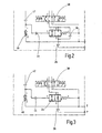
- actuating device serves to control at least one hydraulic consumer 10 in the form of a hydraulic differential cylinder.
- a pertinent differential cylinder could also occur a Gleichgangzylinder or a hydraulic motor and comparable consumers who want to help to a smooth starting behavior.
- the hydraulic consumer 10 in the form of the working cylinder has a piston rod unit 12 which separates two hydraulic working spaces 14,16 from each other. The construction of this working cylinder or actuators is common, so that will not be discussed in more detail here at this point.
- the working space 14 also called piston working space, is connected via a connection A with the actual hydraulic circuit and the working space 16, which is also called bar working space, with the corresponding junction B.
- the terminals S1 and S2 shown in the upper part of the hydraulic circuit seen serve the connection of corresponding sensors, for example for pressure value detection in the corresponding hydraulic lines, each open at the connection points A, B to the outside, wherein the actuating device is preferably designed in the manner of a hydraulic modular control block.
- the actuating device in addition to the Nutzanêtn A, B nor a hydraulic supply port P and a drain T, which preferably opens at ambient pressure in a corresponding supply tank.
- the hydraulic supply at port P can be done via a corresponding hydraulic pump.
- a proportional valve 24 is connected, which forms a kind of throttle or throttle valve.
- Proportional valves are continuously adjustable pressure, flow and directional valves that can convert a variable input signal into a proportional hydraulic output signal.
- a diaphragm 26 is connected, which throttles the fluid supply flow coming from the supply pump so far.
- the proportional valve 24 has two control inputs 28,30, wherein at the control input 28, the fluid pressure at the point 1 of the proportional valve 24 is present and at the control input 30 of the set pressure of a compression spring 32 (see. Figure 4 ).
- the working space of the compression spring 32 is connected via the terminal 4 of the proportional valve 24 and thus via a leakage oil connection 34 with the tank T.
- a diaphragm 36 is connected in the secondary branch between the connection points 2 and 3 of the proportional valve 24, in turn.
- a slide valve 38 is connected to the input 3, which is in the manner of a 4/3-way slide valve is formed with a further connection point 1, which is connected to the tank connection T and to the leakage oil connection 34.
- the pertinent slide valve 38 is spring-centered on both sides held in the initial position shown and can be controlled via appropriate actuation or switching magnets in a known manner.
- the output 4 of the slide valve 38 opens in the direction of the Fig.1 Seen on the right side in the line for the Nutzanschluß B, via the input 1 of the pilot-operated check valve 22.
- the output 4 of the spool valve 38 opens onto the input side 1 of a shuttle valve 40 of known type.
- the other input 3 of the shuttle valve 40 opens to the other output 2 of the slide valve 38.
- For the mutual unlocking of the two check valves 22 open the control lines on the Input side 3 of the check valves 22 each in the opposite feed line for the Nutzan bend A, B.
- the output 2 of the shuttle valve 40 in turn opens via an aperture 42 to the input side 1 with the control input 28, in turn, another aperture 44 is connected.
- a pressure relief valve 46 is connected, which is formed in the present case as a spring-loaded check valve with opening direction in the direction of the tank port T.
- the drive unit designated as a whole by 48 consists essentially of the pressure relief valve 46 and of the orifices 42 and 44.
- the pertinent control unit 48 controls the fluid supply flow for the consumer 10 such that a damped operation is achieved with a gentle starting behavior for the hydraulic consumer 10 in the form of the working cylinder.
- the system pressure prevailing in the region of the shuttle valve 40, which supplies the useful ports A, B, can assume a wide range of pressure values within a certain range of variation and depending on the load acting on the hydraulic cylinder 10, different volume flows occur, in particular with respect to the diaphragm 42 between the shuttle valve 40 and pressure relief valve 46.
- the slide valve 38 is first to be activated, which can take place via a suitable actuation or control device triggered by an operator.
- the pressure relief valve 46 and the acting spring force on the compression spring 32 on the oppositely acting control input side 30 is taking into account the geometry of the piston 50 of the proportional valve 24 (see. Figure 4 ) determines the opening characteristic for the throttle 24 and thus the damping effect for the entire system.
- this also increases the fluid supply flow for the hydraulic consumer 10, the opening behavior of the throttle in the form of the proportional valve 24 being independent of the load pressure at the consumer 10 due to the pressure limiting valve 46. Due to such a steady increase of the fluid flow to the hydraulic consumer 10, this drives smoothly and continuously until it reaches the maximum speed.
- the displaced in the rod working space 16 fluid in the pertinent extension movement of the piston rod unit 12 is pushed over the Nutzanschluß B and the terminal 4 of the spool valve 38 in the direction of the tank port T in the tank.
- the closing element of the shuttle valve 40 is opposite to the representation of the Fig.1 brought into the upper position, which faces in the direction of the input 3 of the shuttle valve 40, so that the input 1 is fluidly connected to the output 2 of the shuttle valve 40 and in turn via the proportional valve 24 in a throttled manner and thus gently the retraction movement of the piston rod unit 12 can be done.
- the aperture 42 has the same aperture diameter as the aperture 36 and that the further aperture 44 has a smaller aperture diameter than the aperture 42 and 36, wherein the pump inlet-side arranged aperture 26 should have the smallest aperture diameter.
- the shuttle valve 40 operates in the manner of a tapping point, wherein a pertinent tapping point (not shown) via other hydraulic means would be realized, but this is associated with a correspondingly increased circuit complexity.
- the combination of an initial throttling via the proportional valve 24 with the inlet panel 36 ensures that pressurized fluid is present on the input side of the actuating or sliding valve 38 even in the non-switched state for the gentle starting process of the consumer.
- Such a delay-free starting is possible and the indicated hydraulic switching unit can basically be used for each hydraulic consumer, even if the requirements for the initial volume flow are different.
- Fig.2 can be closed at the existing aperture 36, the proportional valve in the illustrated switched position, in which case the entire adjustment has to be made via the aperture 36, which optionally also limits the adjustment options for the hydraulic circuit.
- Fig.1 shown combination of initial throttling on the proportional valve 24 with inserted aperture 36 with permanent aperture cross-section makes sense especially from a cost point of view, if the proportional valve 24 is designed for the smallest occurring volume flow and the larger volume flows is realized by the parallel connection of the diaphragm 36 to the proportional valve 24. Also results from the pertinent arrangement, an increased dynamic behavior during soft damped startup of the hydraulic load 10. If the embodiments according to the Fig.2 and 3 towards the solution after the Fig.1 are changed, only the major changes have been explained above and otherwise the same reference numerals are used for the same components, as in Fig. 1 specified.
- the piston 50 would then completely block the pertinent fluid path, so that the compensation can take place via the diaphragm 36.
- a corresponding throttling of the fluid flow of the piston 50 is provided between two piston parts 56,58 with a reduced diameter control or annular groove 60 and the pressure applied to the control input 1 or 28 relative to the constant volume flow is then permanently at the bottom of the piston part 58 on.
- the spring chamber above the piston 50 opens into the leakage oil connection 34, which opens out to the tank side T.
- the actuating device according to the invention is preferably used there in which operating cabins of excavators or cranes have to move several meters forwards or upwards; Adjusting movements of the cabin, as they are necessary to make a timely unloading of ships od. Like. To make, where the operator needs an extended field of view. Thanks to the smooth start-up and stop movements with linear speed and acceleration behavior, the otherwise unpleasant rocking movements of the car which otherwise occur are counteracted, which, in addition to increasing the ease of operation, also meets increased safety requirements.
- the proportional valve 24 is designed in the manner of a continuous valve.
- the proportional valve 24 can be used for poor oil cleanliness classes, which otherwise make the use of conventional proportional valves impossible, provided that they are provided with electrically operable switching or actuating magnet. So far as in the present application of a proportional valve is mentioned, this means a continuous valve without the use of a switching or actuating magnet. Furthermore, all throttles and / or diaphragms used can be protected by sieves against contamination.
Landscapes
- Engineering & Computer Science (AREA)
- Physics & Mathematics (AREA)
- Fluid Mechanics (AREA)
- Mechanical Engineering (AREA)
- General Engineering & Computer Science (AREA)
- Fluid-Pressure Circuits (AREA)
- Operation Control Of Excavators (AREA)
Claims (7)
- Dispositif d'actionnement pour la commande d'un appareil (10) consommateur hydraulique, comme un cylindre de travail, au moyen d'un courant d'alimentation en fluide,- dans lequel, au moyen d'une unité (48) de commande, le courant d'alimentation en fluide de l'appareil (10) consommateur est commandé de manière à obtenir un actionnement amorti en ayant un comportement doux au démarrage,- dans lequel l'unité (48) de commande comporte une vanne (24) proportionnelle qui sert d'étranglement, dont l'effet d'étranglement peut être réglé, au moins en partie, par une entrée (28) de commande d'un courant volumique de fluide constant,- dans lequel, pour l'obtention d'un courant volumique de fluide constant, on monte sur l'un des côtés (28) d'entrée de commande au moins un obturateur (42) qui est raccordé du côté de la sortie à l'entrée d'une vanne (46) de limitation de la pression, et- dans lequel, entre la sortie de l'un des obturateurs (42) et l'entrée (1) de la vanne (46) de limitation de la pression, un autre obturateur (44) est monté dans l'entrée (28) de commande de la vanne (24) proportionnelle,- caractérisé en ce que les deux obturateurs (42, 44) de l'unité (48) de commande ont des diamètres d'obturation différents.
- Dispositif d'actionnement suivant la revendication 1, caractérisé en ce que l'un des obturateurs (42) a un diamètre plus grand que l'autre obturateur (44) dans l'entrée (28) de commande de la vanne (24) proportionnelle.
- Dispositif d'actionnement suivant l'une des revendications 1 à 2, caractérisé en ce que l'autre entrée (30) de commande de la vanne (24) proportionnelle comporte un ressort (32) de compression.
- Dispositif d'actionnement suivant l'une des revendications 1 à 3, caractérisé en ce qu'une vanne (38) à passage directe, notamment une vanne à passage directe 4/3 voies est montée, entre l'appareil (10) consommateur hydraulique et l'unité (48) de commande.
- Dispositif d'actionnement suivant la revendication 4, caractérisé en ce qu'entre la vanne (38) à passage directe et l'appareil (10) consommateur hydraulique est montée, par ses deux entrées (1, 3), une vanne (40) à deux voies, qui est raccordée par sa sortie (2) du côté de l'entrée à l'un des obturateurs (42).
- Dispositif d'actionnement suivant l'une des revendications précédentes, caractérisé en ce qu'un troisième obturateur (36) supplémentaire est monté dans une branche secondaire entre l'entrée et la sortie (3, 2) de la vanne (24) proportionnelle.
- Dispositif d'actionnement suivant l'une des revendications précédentes, caractérisé en ce que la vanne (24) proportionnelle est pourvue, dans une position de départ non actionnée, d'un étranglement de base.
Applications Claiming Priority (2)
| Application Number | Priority Date | Filing Date | Title |
|---|---|---|---|
| DE102006037631A DE102006037631A1 (de) | 2006-08-10 | 2006-08-10 | Betätigungsvorrichtung |
| PCT/EP2007/006179 WO2008017359A1 (fr) | 2006-08-10 | 2007-07-12 | Dispositif d'actionnement |
Publications (2)
| Publication Number | Publication Date |
|---|---|
| EP2049802A2 EP2049802A2 (fr) | 2009-04-22 |
| EP2049802B1 true EP2049802B1 (fr) | 2011-09-07 |
Family
ID=38606463
Family Applications (1)
| Application Number | Title | Priority Date | Filing Date |
|---|---|---|---|
| EP07786011A Not-in-force EP2049802B1 (fr) | 2006-08-10 | 2007-07-12 | Dispositif d'actionnement |
Country Status (4)
| Country | Link |
|---|---|
| EP (1) | EP2049802B1 (fr) |
| AT (1) | ATE523698T1 (fr) |
| DE (1) | DE102006037631A1 (fr) |
| WO (1) | WO2008017359A1 (fr) |
Families Citing this family (4)
| Publication number | Priority date | Publication date | Assignee | Title |
|---|---|---|---|---|
| DE102009040347A1 (de) * | 2009-09-05 | 2011-03-10 | Alpha Fluid Hydrauliksysteme Müller GmbH | Schaltungs-,Ansteuerungs- und Regelkonzeption für autarke, weggeregelte elektrohydraulische Aktoren |
| EP2829504A1 (fr) * | 2013-07-23 | 2015-01-28 | Palfinger Platforms GmbH | Procédé de commande d'une machine de travail et système hydraulique pour une plate-forme élévatrice |
| DE102014205233A1 (de) | 2014-03-20 | 2015-09-24 | Deere & Company | Erntemaschine mit vorausschauender Vortriebsgeschwindigkeitsvorgabe |
| EP3330111B1 (fr) * | 2016-12-02 | 2023-02-01 | Husco International, Inc. | Système de suspension pour un véhicule tout terrain |
Family Cites Families (7)
| Publication number | Priority date | Publication date | Assignee | Title |
|---|---|---|---|---|
| JPH0742705A (ja) * | 1993-07-30 | 1995-02-10 | Yutani Heavy Ind Ltd | 作業機械の油圧装置 |
| US6814409B2 (en) | 2001-04-12 | 2004-11-09 | A-Dec, Inc. | Hydraulic drive system |
| DE10122297C1 (de) * | 2001-05-08 | 2002-06-27 | Festo Ag & Co | Vorrichtung zur gedämpften Positionierung eines in einem Zylinder verschiebbaren Kolbens in einer Anschlagposition |
| US6578855B2 (en) * | 2001-07-11 | 2003-06-17 | Deere & Company | Vehicle suspension control system |
| ATE323836T1 (de) * | 2001-11-28 | 2006-05-15 | Bosch Rexroth Ag | Antrieb |
| DE102004005606B3 (de) * | 2004-02-05 | 2005-10-06 | Hydac Fluidtechnik Gmbh | Schaltungsanordnung |
| DE202004014029U1 (de) * | 2004-09-08 | 2006-01-12 | Hawe Hydraulik Gmbh & Co. Kg | Elektrohydraulische Steuervorrichtung |
-
2006
- 2006-08-10 DE DE102006037631A patent/DE102006037631A1/de not_active Withdrawn
-
2007
- 2007-07-12 EP EP07786011A patent/EP2049802B1/fr not_active Not-in-force
- 2007-07-12 WO PCT/EP2007/006179 patent/WO2008017359A1/fr not_active Ceased
- 2007-07-12 AT AT07786011T patent/ATE523698T1/de active
Also Published As
| Publication number | Publication date |
|---|---|
| DE102006037631A1 (de) | 2008-02-14 |
| WO2008017359A8 (fr) | 2008-05-29 |
| ATE523698T1 (de) | 2011-09-15 |
| EP2049802A2 (fr) | 2009-04-22 |
| WO2008017359A1 (fr) | 2008-02-14 |
Similar Documents
| Publication | Publication Date | Title |
|---|---|---|
| DE10344480B3 (de) | Hydraulische Ventilanordnung | |
| DE102004012382B4 (de) | Hydraulische Anordnung | |
| EP1989450B1 (fr) | Dispositif de commande hydraulique | |
| DE10307346A1 (de) | Ventilanordnung | |
| DE102011106307A1 (de) | Steueranordnung und Verfahren zum Ansteuern von mehreren hydraulischen Verbrauchern | |
| EP0016719B1 (fr) | Dispositif de commande pour moteur hydraulique | |
| DE10330869A1 (de) | Hydraulisches System | |
| DE102012207422A1 (de) | Hydraulische Steueranordnung mit Lastdruckminderungund hydraulischer Ventilblock dafür | |
| EP3816455A1 (fr) | Dispositif de commande hydraulique destiné à l'alimentation en fluide de pression d'au moins deux consommateurs hydrauliques | |
| EP1710445A2 (fr) | Dispositif de contrôle hydraulique | |
| WO2009062564A1 (fr) | Mécanisme hydraulique à soupape | |
| EP1743981A1 (fr) | Agencement hydraulique | |
| EP2142808B1 (fr) | Ensemble de commande hydraulique | |
| EP2049802B1 (fr) | Dispositif d'actionnement | |
| DE10219717B3 (de) | Hydraulische Ventilanordnung | |
| EP2535624A1 (fr) | Clapet de limitation de pression | |
| DE10340505B4 (de) | Ventilanordnung zur Steuerung eines Hydraulikantriebs | |
| DE112022005139T5 (de) | Hydrauliksteuersystem in einer Arbeitsmaschine | |
| EP2513491B1 (fr) | Systeme de vanne pour commander un consommateur | |
| WO2003087585A1 (fr) | Systeme de commande hydraulique faisant appel au principe de la sensibilite de charge | |
| EP0603722A1 (fr) | Dispositif de commande hydraulique | |
| WO2005093263A1 (fr) | Systeme de commande hydraulique | |
| DE102007045802A1 (de) | Hydraulische Steueranordnung | |
| WO2001060734A1 (fr) | Dispositif servant a reguler la fonction d'inclinaison d'un mat de levage, notamment pour un chariot a fourche | |
| WO2005021978A1 (fr) | Soupape a commande hydraulique pourvue d'au moins une unite de commande hydraulique |
Legal Events
| Date | Code | Title | Description |
|---|---|---|---|
| PUAI | Public reference made under article 153(3) epc to a published international application that has entered the european phase |
Free format text: ORIGINAL CODE: 0009012 |
|
| 17P | Request for examination filed |
Effective date: 20081224 |
|
| AK | Designated contracting states |
Kind code of ref document: A2 Designated state(s): AT BE BG CH CY CZ DE DK EE ES FI FR GB GR HU IE IS IT LI LT LU LV MC MT NL PL PT RO SE SI SK TR |
|
| AX | Request for extension of the european patent |
Extension state: AL BA HR MK RS |
|
| DAX | Request for extension of the european patent (deleted) | ||
| 17Q | First examination report despatched |
Effective date: 20101112 |
|
| GRAC | Information related to communication of intention to grant a patent modified |
Free format text: ORIGINAL CODE: EPIDOSCIGR1 |
|
| GRAP | Despatch of communication of intention to grant a patent |
Free format text: ORIGINAL CODE: EPIDOSNIGR1 |
|
| GRAS | Grant fee paid |
Free format text: ORIGINAL CODE: EPIDOSNIGR3 |
|
| GRAA | (expected) grant |
Free format text: ORIGINAL CODE: 0009210 |
|
| REG | Reference to a national code |
Ref country code: GB Ref legal event code: FG4D Free format text: NOT ENGLISH |
|
| REG | Reference to a national code |
Ref country code: CH Ref legal event code: EP Ref country code: CH Ref legal event code: NV Representative=s name: ISLER & PEDRAZZINI AG |
|
| REG | Reference to a national code |
Ref country code: IE Ref legal event code: FG4D Free format text: LANGUAGE OF EP DOCUMENT: GERMAN |
|
| REG | Reference to a national code |
Ref country code: SE Ref legal event code: TRGR |
|
| REG | Reference to a national code |
Ref country code: DE Ref legal event code: R096 Ref document number: 502007008107 Country of ref document: DE Effective date: 20111103 |
|
| REG | Reference to a national code |
Ref country code: NL Ref legal event code: VDEP Effective date: 20110907 |
|
| PG25 | Lapsed in a contracting state [announced via postgrant information from national office to epo] |
Ref country code: LT Free format text: LAPSE BECAUSE OF FAILURE TO SUBMIT A TRANSLATION OF THE DESCRIPTION OR TO PAY THE FEE WITHIN THE PRESCRIBED TIME-LIMIT Effective date: 20110907 |
|
| LTIE | Lt: invalidation of european patent or patent extension |
Effective date: 20110907 |
|
| PG25 | Lapsed in a contracting state [announced via postgrant information from national office to epo] |
Ref country code: CY Free format text: LAPSE BECAUSE OF FAILURE TO SUBMIT A TRANSLATION OF THE DESCRIPTION OR TO PAY THE FEE WITHIN THE PRESCRIBED TIME-LIMIT Effective date: 20110907 Ref country code: SI Free format text: LAPSE BECAUSE OF FAILURE TO SUBMIT A TRANSLATION OF THE DESCRIPTION OR TO PAY THE FEE WITHIN THE PRESCRIBED TIME-LIMIT Effective date: 20110907 Ref country code: GR Free format text: LAPSE BECAUSE OF FAILURE TO SUBMIT A TRANSLATION OF THE DESCRIPTION OR TO PAY THE FEE WITHIN THE PRESCRIBED TIME-LIMIT Effective date: 20111208 Ref country code: LV Free format text: LAPSE BECAUSE OF FAILURE TO SUBMIT A TRANSLATION OF THE DESCRIPTION OR TO PAY THE FEE WITHIN THE PRESCRIBED TIME-LIMIT Effective date: 20110907 |
|
| REG | Reference to a national code |
Ref country code: IE Ref legal event code: FD4D |
|
| PG25 | Lapsed in a contracting state [announced via postgrant information from national office to epo] |
Ref country code: IS Free format text: LAPSE BECAUSE OF FAILURE TO SUBMIT A TRANSLATION OF THE DESCRIPTION OR TO PAY THE FEE WITHIN THE PRESCRIBED TIME-LIMIT Effective date: 20120107 Ref country code: SK Free format text: LAPSE BECAUSE OF FAILURE TO SUBMIT A TRANSLATION OF THE DESCRIPTION OR TO PAY THE FEE WITHIN THE PRESCRIBED TIME-LIMIT Effective date: 20110907 Ref country code: CZ Free format text: LAPSE BECAUSE OF FAILURE TO SUBMIT A TRANSLATION OF THE DESCRIPTION OR TO PAY THE FEE WITHIN THE PRESCRIBED TIME-LIMIT Effective date: 20110907 Ref country code: IE Free format text: LAPSE BECAUSE OF FAILURE TO SUBMIT A TRANSLATION OF THE DESCRIPTION OR TO PAY THE FEE WITHIN THE PRESCRIBED TIME-LIMIT Effective date: 20110907 |
|
| PG25 | Lapsed in a contracting state [announced via postgrant information from national office to epo] |
Ref country code: PL Free format text: LAPSE BECAUSE OF FAILURE TO SUBMIT A TRANSLATION OF THE DESCRIPTION OR TO PAY THE FEE WITHIN THE PRESCRIBED TIME-LIMIT Effective date: 20110907 Ref country code: EE Free format text: LAPSE BECAUSE OF FAILURE TO SUBMIT A TRANSLATION OF THE DESCRIPTION OR TO PAY THE FEE WITHIN THE PRESCRIBED TIME-LIMIT Effective date: 20110907 Ref country code: PT Free format text: LAPSE BECAUSE OF FAILURE TO SUBMIT A TRANSLATION OF THE DESCRIPTION OR TO PAY THE FEE WITHIN THE PRESCRIBED TIME-LIMIT Effective date: 20120109 Ref country code: NL Free format text: LAPSE BECAUSE OF FAILURE TO SUBMIT A TRANSLATION OF THE DESCRIPTION OR TO PAY THE FEE WITHIN THE PRESCRIBED TIME-LIMIT Effective date: 20110907 Ref country code: RO Free format text: LAPSE BECAUSE OF FAILURE TO SUBMIT A TRANSLATION OF THE DESCRIPTION OR TO PAY THE FEE WITHIN THE PRESCRIBED TIME-LIMIT Effective date: 20110907 |
|
| PLBE | No opposition filed within time limit |
Free format text: ORIGINAL CODE: 0009261 |
|
| STAA | Information on the status of an ep patent application or granted ep patent |
Free format text: STATUS: NO OPPOSITION FILED WITHIN TIME LIMIT |
|
| PG25 | Lapsed in a contracting state [announced via postgrant information from national office to epo] |
Ref country code: DK Free format text: LAPSE BECAUSE OF FAILURE TO SUBMIT A TRANSLATION OF THE DESCRIPTION OR TO PAY THE FEE WITHIN THE PRESCRIBED TIME-LIMIT Effective date: 20110907 |
|
| 26N | No opposition filed |
Effective date: 20120611 |
|
| REG | Reference to a national code |
Ref country code: DE Ref legal event code: R097 Ref document number: 502007008107 Country of ref document: DE Effective date: 20120611 |
|
| BERE | Be: lapsed |
Owner name: HYDAC FLUIDTECHNIK G.M.B.H. Effective date: 20120731 |
|
| PG25 | Lapsed in a contracting state [announced via postgrant information from national office to epo] |
Ref country code: MC Free format text: LAPSE BECAUSE OF NON-PAYMENT OF DUE FEES Effective date: 20120731 |
|
| PG25 | Lapsed in a contracting state [announced via postgrant information from national office to epo] |
Ref country code: ES Free format text: LAPSE BECAUSE OF FAILURE TO SUBMIT A TRANSLATION OF THE DESCRIPTION OR TO PAY THE FEE WITHIN THE PRESCRIBED TIME-LIMIT Effective date: 20111218 |
|
| PG25 | Lapsed in a contracting state [announced via postgrant information from national office to epo] |
Ref country code: BE Free format text: LAPSE BECAUSE OF NON-PAYMENT OF DUE FEES Effective date: 20120731 |
|
| PG25 | Lapsed in a contracting state [announced via postgrant information from national office to epo] |
Ref country code: BG Free format text: LAPSE BECAUSE OF FAILURE TO SUBMIT A TRANSLATION OF THE DESCRIPTION OR TO PAY THE FEE WITHIN THE PRESCRIBED TIME-LIMIT Effective date: 20111207 |
|
| PG25 | Lapsed in a contracting state [announced via postgrant information from national office to epo] |
Ref country code: MT Free format text: LAPSE BECAUSE OF FAILURE TO SUBMIT A TRANSLATION OF THE DESCRIPTION OR TO PAY THE FEE WITHIN THE PRESCRIBED TIME-LIMIT Effective date: 20110907 |
|
| REG | Reference to a national code |
Ref country code: AT Ref legal event code: MM01 Ref document number: 523698 Country of ref document: AT Kind code of ref document: T Effective date: 20120731 |
|
| PG25 | Lapsed in a contracting state [announced via postgrant information from national office to epo] |
Ref country code: AT Free format text: LAPSE BECAUSE OF NON-PAYMENT OF DUE FEES Effective date: 20120731 |
|
| PG25 | Lapsed in a contracting state [announced via postgrant information from national office to epo] |
Ref country code: TR Free format text: LAPSE BECAUSE OF FAILURE TO SUBMIT A TRANSLATION OF THE DESCRIPTION OR TO PAY THE FEE WITHIN THE PRESCRIBED TIME-LIMIT Effective date: 20110907 |
|
| PG25 | Lapsed in a contracting state [announced via postgrant information from national office to epo] |
Ref country code: LU Free format text: LAPSE BECAUSE OF NON-PAYMENT OF DUE FEES Effective date: 20120712 |
|
| PG25 | Lapsed in a contracting state [announced via postgrant information from national office to epo] |
Ref country code: HU Free format text: LAPSE BECAUSE OF FAILURE TO SUBMIT A TRANSLATION OF THE DESCRIPTION OR TO PAY THE FEE WITHIN THE PRESCRIBED TIME-LIMIT Effective date: 20070712 |
|
| REG | Reference to a national code |
Ref country code: FR Ref legal event code: PLFP Year of fee payment: 9 |
|
| PGFP | Annual fee paid to national office [announced via postgrant information from national office to epo] |
Ref country code: GB Payment date: 20150505 Year of fee payment: 9 |
|
| PGFP | Annual fee paid to national office [announced via postgrant information from national office to epo] |
Ref country code: FR Payment date: 20150506 Year of fee payment: 9 |
|
| PGFP | Annual fee paid to national office [announced via postgrant information from national office to epo] |
Ref country code: DE Payment date: 20150701 Year of fee payment: 9 Ref country code: FI Payment date: 20150728 Year of fee payment: 9 Ref country code: CH Payment date: 20150713 Year of fee payment: 9 |
|
| PGFP | Annual fee paid to national office [announced via postgrant information from national office to epo] |
Ref country code: SE Payment date: 20150720 Year of fee payment: 9 |
|
| PGFP | Annual fee paid to national office [announced via postgrant information from national office to epo] |
Ref country code: IT Payment date: 20150710 Year of fee payment: 9 |
|
| REG | Reference to a national code |
Ref country code: DE Ref legal event code: R119 Ref document number: 502007008107 Country of ref document: DE |
|
| REG | Reference to a national code |
Ref country code: CH Ref legal event code: PL |
|
| REG | Reference to a national code |
Ref country code: SE Ref legal event code: EUG |
|
| GBPC | Gb: european patent ceased through non-payment of renewal fee |
Effective date: 20160712 |
|
| PG25 | Lapsed in a contracting state [announced via postgrant information from national office to epo] |
Ref country code: CH Free format text: LAPSE BECAUSE OF NON-PAYMENT OF DUE FEES Effective date: 20160731 Ref country code: FI Free format text: LAPSE BECAUSE OF NON-PAYMENT OF DUE FEES Effective date: 20160712 Ref country code: LI Free format text: LAPSE BECAUSE OF NON-PAYMENT OF DUE FEES Effective date: 20160731 Ref country code: SE Free format text: LAPSE BECAUSE OF NON-PAYMENT OF DUE FEES Effective date: 20160713 Ref country code: DE Free format text: LAPSE BECAUSE OF NON-PAYMENT OF DUE FEES Effective date: 20170201 Ref country code: FR Free format text: LAPSE BECAUSE OF NON-PAYMENT OF DUE FEES Effective date: 20160801 |
|
| REG | Reference to a national code |
Ref country code: FR Ref legal event code: ST Effective date: 20170331 |
|
| PG25 | Lapsed in a contracting state [announced via postgrant information from national office to epo] |
Ref country code: GB Free format text: LAPSE BECAUSE OF NON-PAYMENT OF DUE FEES Effective date: 20160712 |
|
| PG25 | Lapsed in a contracting state [announced via postgrant information from national office to epo] |
Ref country code: IT Free format text: LAPSE BECAUSE OF NON-PAYMENT OF DUE FEES Effective date: 20160712 |