EP2050100B1 - System zur verabreichung eines stabilisierten röntgenstrahls - Google Patents
System zur verabreichung eines stabilisierten röntgenstrahls Download PDFInfo
- Publication number
- EP2050100B1 EP2050100B1 EP07823313A EP07823313A EP2050100B1 EP 2050100 B1 EP2050100 B1 EP 2050100B1 EP 07823313 A EP07823313 A EP 07823313A EP 07823313 A EP07823313 A EP 07823313A EP 2050100 B1 EP2050100 B1 EP 2050100B1
- Authority
- EP
- European Patent Office
- Prior art keywords
- stabilisation
- source
- conditioning
- area
- obturation
- Prior art date
- Legal status (The legal status is an assumption and is not a legal conclusion. Google has not performed a legal analysis and makes no representation as to the accuracy of the status listed.)
- Not-in-force
Links
Images



Classifications
-
- H—ELECTRICITY
- H05—ELECTRIC TECHNIQUES NOT OTHERWISE PROVIDED FOR
- H05G—X-RAY TECHNIQUE
- H05G1/00—X-ray apparatus involving X-ray tubes; Circuits therefor
- H05G1/02—Constructional details
-
- G—PHYSICS
- G21—NUCLEAR PHYSICS; NUCLEAR ENGINEERING
- G21K—HANDLING OF PARTICLES OR IONISING RADIATION NOT OTHERWISE PROVIDED FOR; IRRADIATION DEVICES; GAMMA RAY OR X-RAY MICROSCOPES
- G21K1/00—Arrangements for handling particles or ionising radiation, e.g. focusing or moderating
- G21K1/02—Arrangements for handling particles or ionising radiation, e.g. focusing or moderating using diaphragms, collimators
- G21K1/04—Arrangements for handling particles or ionising radiation, e.g. focusing or moderating using diaphragms, collimators using variable diaphragms, shutters, choppers
Definitions
- the invention relates to X-ray beam delivery systems.
- Such X-ray beam delivery systems are used in particular in diffraction, reflectometry or X-ray fluorescence equipment.
- Such equipment finds applications, for example, in the field of metrology, and more particularly in the field of metrology to perform part controls or process drift controls for semiconductor manufacturing applications.
- the X-ray beam delivery system generates a beam that is directed to a sample to perform analyzes such as diffraction, fluorescence or reflectometry measurements.
- analyzes such as diffraction, fluorescence or reflectometry measurements.
- the analysis of the X-ray beam diffracted by the sample or the analysis of the RX fluorescence generated by this sample makes it possible to deduce characteristics of this sample, for example thicknesses of thin layers deposited on its surface. , mechanical stress levels of these thin layers, or phase analyzes of materials.
- the delivery systems must allow to obtain beams having at the sample level precise characteristics.
- the conditioning means allow to monochromatize, focus or collimate the beam.
- the stability performances of existing delivery systems have even more penalizing limits when they include beam shaping orifices whose size is very small and typically has a diameter less than 100 ⁇ m.
- solutions proposing alignment and control systems of the position of the RX spot output with a servo on the alignment of the optical blocks and the collimator to overcome some misalignments do not allow to find a satisfactory stability in a reasonable delay.
- This stabilization of the beam must thus be able to be typically done in a few tens of seconds in the case of a hot opening, that is to say with a system put to sleep at a reduced power of the source, or in a few tens minutes in the case of cold ignition of the source.
- the aim of the invention is to improve the existing X-ray beam delivery systems and in particular to improve their spatial or temporal stability.
- an X-ray beam delivery system according to claim 1 is provided within the scope of the present invention.
- the system according to the invention makes it possible to limit heat transfer downstream of the source block.
- the disturbances of the conditioning means due in particular to the temperature variations generated by the sealing means are therefore limited.
- the spatial and temporal stabilities of the delivered beam are improved.
- the conditioning means are in fact protected from any external thermal disturbance, which may be derived from the devices surrounding the conditioning means (such as, for example, the sealing means), or even from the external temperature variation properly speaking.
- the invention further relates to a method of stabilizing an X-ray beam according to claim 15.
- the source block 100 The source block 100
- the source block 100 includes in particular a source for generating an X-ray source beam through a source orifice.
- the direction of propagation of the waves constituting the source beam defines an upstream direction and a downstream direction 11 in a propagation direction determined by the direction of the beam delivered by the X-ray beam delivery system 1.
- the source block 100 comprises an X-ray tube disposed in a protective sheath, the sheath providing X-ray radiation protection and possibly pre-cooling of the X-ray tube.
- the tube may be immersed in a heat transfer fluid contained in the sheath and providing pre-cooling.
- the source block further comprises cooling means for maintaining the tube at temperatures typically below 45 ° C.
- these cooling means comprise a cooling shell 102.
- It may be a shell of conductive material affixed to the sheath or to a portion of the sheath containing heat transfer liquids such as glycol water providing cooling by forced convection.
- the cooling shell 102 is thus connected to a remote external heat exchanger for undoing the coolant heat that it has accumulated in the cooling shell.
- the connection is made at the inlet tips 104 and 105.
- the external heat exchanger, the cooling shell 102 are also connected to a remote pump of the beam delivery system to ensure the cycle of the coolant .
- the exchanger, the cooling shell, the connections and the pump thus define a closed circuit.
- the protective sheath may also be cooled by a radiator affixed for example above the source to ventilate the protective sheath.
- the cooling shell 102 of the source block 100 thus defines an outer envelope constituting a cooling zone 102 of the source.
- the X-ray tube is a low-power micro-focus tube.
- Low power means an X-ray source comprising an electron gun generating an electron beam of an electronic power typically less than 100 Watts (or of the order of a few hundred Watts), this electron beam being intended impacting the anode of the X-ray tube to generate X-rays of desired energy.
- the apparent focus of such a micro-focus source is typically less than 100 microns.
- the apparent focus corresponds to the focus as "seen” by the adjacent optical elements when these are typically placed at an angle of 6 ° to the tube anode surface (this angle corresponds to the angle of elevation of the optics relative to the surface of the anode of the tube and is commonly called in Anglo-Saxon term “take-off angle”).
- This type of X-ray tube is available from Oxford X-ray Technology based in Scott Valley, California, or from RTW Röntgentechnik GmbH.
- the amount of heat generated by the source is important which requires adequate sizing of the cooling capacity of the cooling system 1. It is specified that typically 99% of the power of the electron beam impacting the anode is dissipated into heat energy and 1% of the energy is dissipated in X-rays. A large part of the energy of the electron beam is thus dissipated. in thermal energy on the anode, the latter radiating part of this heat on the walls of the X-ray tube.
- the invention is not limited to the use of this type of tubes and higher power tubes may be used.
- the dimensioning of the cooling means of the source will have to be adapted.
- the source block 100 may comprise instead of a sealed tube an RX source of the rotating anode type.
- the tube may be an anode tube of copper, molybdenum or tungsten.
- the packaging means 500 The packaging means 500
- the purpose of the conditioning means 500 is to collect the beam emitted by the source and to process it spatially and spectrally in order to shape it in the direction of a sample. They are arranged downstream of the source block.
- Energy filtration and focusing or collimation are in particular ensured by an optical block 520 arranged in the direction of propagation of the beam, downstream of the source.
- the optics may be multi-layered optics or a natural crystal for X-ray diffraction, and shaped to provide a focus or collimation effect in one or two dimensions as needed.
- the optic can also be a monocapillary or polycapillary optic.
- the optics is included in a sarcophagus.
- This sarcophagus provides radiation protection and a vacuum or light inert gas Helium type of optics, to limit the absorption of X-rays.
- under vacuum also protects the surface against surface degradation phenomena activated by exposure X-rays in air.
- Alignment screws 540 align the optics and / or the sarcophagus with the source.
- mirrors producing one-dimensional or two-dimensional focusing or collimating effects may be used.
- multi-layered mirrors producing effects in two dimensions single-reflection mirrors having evolved shapes of the type of those defined in FR 2 841 371 or Kirkpatrick-Baez mirrors attached or dissociated may be used.
- the collimator 530 The collimator 530
- the conditioning means 500 may also comprise a collimator 530 making it possible to shape the beam in order to obtain an RX spot of desired size and shape at the sample and to limit the background noise of the X-rays. disseminated.
- the attenuation of the background noise can be obtained for example by absorption of the scattered radiation on all the parts of the delivery system 1 by means of a combination of slots and baffles.
- the shaping of the beam makes it possible to obtain an RX spot of desired size and shape at the sample level.
- This shaping of the beam is typically obtained by means of dedicated orifices, designated hereafter by their usual and Anglo-Saxon terminology "pinhole”.
- Such pinhole may be disposed at the downstream end of the packaging means 500 in a support member 532 carried by an outlet nozzle 531.
- the pinhole mainly has a bore of very small and precise diameter through which the beam passes.
- the pinhole is close to the focal point of the optics close to the sample to be analyzed and has a diameter of its bore less than 100 microns.
- the diameter dimension of the pinhole is typically between 80 and 30 microns.
- the invention will not be limited to delivery systems using focusing optics but will also apply to systems using collimating optics.
- conditioning means 500 may be limited either to the optical block 520 or to the collimator 530.
- the shutter means 400 The shutter means 400
- the shutter means 400 comprise a control member 401, a control member support 402, a shutter.
- These shutter means 400 are arranged downstream of the source block 100.
- the role of the shutter means 400 is to ensure a blocking of the source beam at the source orifice.
- This blocking is provided by the shutter, which comprises a shutter plate in the form of a solid piece, a material sufficiently heavy to absorb the entire source beam.
- the displacement of the shutter from a blocking position of the beam to an open position of the source and vice versa is controlled by the control member 401.
- the shutter means 400 ensure the safety of the system 1 in that they block the source beam in any situation other than an operator controlled opening.
- This shutter is thus designed to be able to move and hold in the locked position in case of power failure.
- This type of shutter is thus commonly known as a safety shutter.
- the control member 401 comprises an electromagnet coil controlled from the outside by an operator. These coils can be surrounded by air, as shown in the example of figure 1 , which allows good thermal insulation and offers greater tolerance to vibrations possibly caused by the movement of the shutter in the shutter guide.
- the controls may also, in other devices, be in contact with the outer walls of these closure means 400.
- the controller 401 includes a servomotor.
- the control member support 402 allows stable mechanical maintenance of the control member 401 on the delivery system 1.
- the shutter may also be in the form of an enclosure for containing substantially sealing the control member 401.
- the system 1 also comprises a shutter guide providing the reciprocating guidance of the shutter between a source blocking position and an opening position of the source.
- rapid shutter means 450 have the role of ensuring a very fast and perfectly controlled blocking of the beam to allow very short exposure times of the sample.
- fast shutter means 450 are especially used for crystallography-type diffractometry applications.
- the response time of the fast shutter means is typically of the order of a few milliseconds, and the response time of the safety shut-off means is typically of the order of a few tens of milliseconds.
- These fast shutter means 450 may be arranged along the direction of the beam between the source block 100 and the downstream end of the X-ray beam delivery system 1.
- These fast shutter means 450 may operate in particular on a rotation principle as is known from the state of the art or on a sliding principle.
- stabilization means 800 and their arrangement in the system 1 also depend on the way in which the conditioning means 500 are connected to the other elements of the system 1.
- packaging means 500 are usually arranged cantilevered with respect to the source block 100, it is also possible to provide a support bracket 700 whose function is to ensure the mechanical strength and the rigidity of the system 1.
- This bracket 700 is disposed downstream of the source block 100.
- Delivery systems including figures 1a , 1b , 2b , 3a, 3c are examples, include a support square 700 forming a mechanical support for the conditioning means 500.
- This bracket 700 is generally in contact with a part of the closure means 400 and with a part of the conditioning means 500.
- This bracket 700 is therefore likely to constitute a thermal bridge capable of promoting a transfer of heat from the closure means 400 to the conditioning means 500.
- the shutter means 400 and the packaging means 500 are supported by means of robust mechanical interfaces. These interfaces usually made of metal allow heat transfer by conduction.
- the stabilization means 800 The stabilization means 800
- the author of the present invention has discovered that during the passage from a closed position to an open position the shutter means 400 can generate a slight increase in temperature likely to influence the spatial and temporal stability of the beam X-ray generated by the system.
- the control member 401 consumes a power of a few watts to a few tens of Watts to keep the shutter in the open position.
- the control member 401 thus releases a thermal power. This thermal power can be released relatively continuously since the safety shutters can be kept open for several tens of minutes or several hours.
- thermal disturbances generated by the shutter means 400 propagate by conduction on the walls of the optical block 520 and the collimator 530 as well as on the shaping pins of the beam.
- the zones of the system 1 subjected to such temperature variations undergo a thermal expansion that can cause a spatial and temporal instability of the beam.
- the thermal disturbances are essentially generated by elements external to the conditioning means as such. It is therefore important to be able to limit these thermal disturbances generated from outside the conditioning means. Indeed, if the interaction of the X-ray beam with the active surface means In theory, the conditioning circuit can generate a heating of the latter, such an internal thermal disturbance can be neglected within the scope of the invention with regard to the considered fields of application for which the power dissipated at the level of the active surface is the same. order of a few milliwatts.
- the delivery system 1 comprises stabilization means 800.
- These stabilization means 800 have the function of thermally stabilizing an area located downstream of the source block.
- thermally stabilizing an area means maintaining this zone at a substantially constant temperature.
- stabilization means 800 ensure a transfer of heat from an area to be stabilized to a cooled zone or thermally stabilized.
- the heat generated by the control member 401 is not transmitted by conduction to the conditioning means 500.
- the conditioning means 500 are therefore not subject to temperature variations and the spatial and temporal stabilities of the system 1 of X-ray beam delivery is therefore not disturbed.
- stabilization means 800 can be envisaged. Some of these solutions are described in detail below and should not be considered as limiting the teachings of the present invention.
- An area of the system 1 stabilized by stabilizing means 800 is designated thereafter zone to be stabilized.
- the areas to be stabilized are located downstream of the source block 100.
- the cooling means of the source are not disposed downstream of the source block 100 and are therefore not stabilizing means 800 within the meaning of the present application.
- the location of the zone to be stabilized must be chosen so as to prevent temperature disturbances from reaching the conditioning means.
- These stabilization means 800 are intended to carry out a transfer of heat between two zones by thermal conduction.
- Shutter stabilization means associated with the supports of the control member 401.
- the stabilizing means 800 may comprise a cooled part 830 by convection of a heat transfer liquid.
- This part may in particular be a cooled part by forced convection of a heat transfer liquid circulating inside the room.
- the liquid can thus circulate in a coil inserted in the room to ensure a guided flow.
- the cooled part 830 can be connected to the cooling circuit of the cooling shell 102 of the source if it is cooled by forced convection with the same type of heat-transfer liquid.
- This cooled part 830 may be placed in contact with the supports of the control member 401, in particular on the opposite side to the source block, in order to improve the compactness of the system in order to position the conditioning means as close as possible to the source, which increases the solid angles of collection at the level of optics.
- This principle is illustrated on Figures 2a, 2b, 2c .
- the cooled part is also in contact with this bracket 700 to ensure stabilization of both the optical block 520 and the collimator 530.
- This configuration is represented in figure 2b .
- an aluminum part about 1 cm thick cooled by circulation of brine with a temperature of 25 ° C at the input of the piece stabilizes the system 1 to achieve the performance mentioned above.
- the interface piece 600 providing mechanical support between the source block 100 and the conditioning means 500 must be dimensioned so as to ensure sufficient mechanical strength of the system 1 despite the provision cantilever of the conditioning means 500 with respect to the source block 100.
- This interface piece 600 is therefore likely to be more massive and to have a surface contact with the shutter means 400 larger than in the case of an assembly with bracket 700.
- This interface piece 600 therefore tends to favor thermal exchanges between the various elements of the system 1.
- a cooled part 830 As described above between the interface piece 600 and the conditioning means 500.
- a cooled part 830 has a thickness of about 1 cm.
- the Figure 2c provides an example of this configuration.
- the supports of the control member 401 are in contact with a strongly conductive part.
- This highly conductive part 810 is for example made of a metal including copper, or aluminum.
- the copper parts will be especially nickel-plated copper in order to limit copper contamination which is highly undesirable for this industry.
- This piece is brought into contact with the supports of the control member 401 and with a zone of the hull of cooling 102 on the other hand.
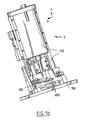
- the figures 1a and 1b illustrate such an arrangement.
- This highly conductive part 810 thus provides a thermal bridge between these two elements and thus promotes thermal transfer by conduction of the heat generated by the control member 401 to the cooling zone 102 of the source block 100.
- an aluminum cooling shell whose outer surface is maintained at an ambient temperature of the order of 25.degree. C. for example by forced convection cooling of a coolant circulating in the shell, and associated with the highly conductive part 810 ensures such cooling.
- This stabilization solution involving a strongly conductive part 810 provides a good stabilization of the shutter means 400 and a greatly reduced size.
- the shutter means 400 comprise a shutter passing from an open position to a sliding lock position
- the highly conductive part 810 has a certain elasticity
- Such a highly conductive part 810 may especially consist of a thin sheet of copper or aluminum. This plate has for example a thickness of 1mm.
- this highly conductive part 810 has a bend formed by bending. Such a geometry makes it possible to substantially increase the capacity of this part to absorb the vibrations generated by the sliding of the shutter.
- a stabilization of the shutter means 400 by contacting a highly conductive part 810 is particularly effective for the stabilization of a coil consuming a power of the order of 20 Watts.
- the stabilization means 800 comprise a heat pipe 850 or a heat pipe network.
- Heatpipes 850 are used very effectively to remove a significant amount of heat from a limited contact area.
- a heat pipe 850 usually has a hermetic enclosure which encloses a liquid in equilibrium with its vapor phase. The heat transfer is carried out passively, by cycles of evaporation of the liquid on the part to be cooled designated evaporator zone 851 and condensation on the cold part called condenser zone 852.
- the steam flows from the evaporator zone 851 to the capacitor zone 852 by overpressure and the condensate flows in the opposite direction by capillary effect.
- This effect can be caused by a porous medium disposed on the inner walls of the capillary. The effect may be accentuated by the gravity resulting from inclination of the tube.
- Heat pipe cooling 850 has the advantage of easily integrating into an X-ray beam delivery system 1 because it does not require water connections.
- the heat pipes 850 therefore offer a great deal of flexibility in the design of the configurations of the X-ray beam delivery systems.
- heat pipes have a very good thermal efficiency. Indeed, the thermal conductivity of a heat pipe 850 is a thousand times greater than that of a copper tube of equivalent dimensions.
- the thermal stabilization of the areas to be stabilized is provided by the provision of heat pipe 850 without additional radiators, the cooling of the condenser portion of the heat pipes 850 being provided by the cooling zone 102 of the source block 100.
- heat pipes is particularly advantageous in the case where the area to be stabilized is located at a significant distance, typically greater than a few centimeters from the cooling zone of the source because of its high thermal conductivity.
- This principle is illustrated in particular in figure 3c where a heat pipe 850 is used to evacuate the calories of a quick shutter 450 which can thus be placed about 20 centimeters from the source block 100.
- Heat pipes may also be used effectively to effect a thermal bridge between the cooling zone 102 of the source block 100 and the zone to be stabilized when this thermal bridge is to be made through a part made of a material with a low thermal conductivity such as than stainless steel.
- bracket 700 For assemblies with bracket 700, it will also be possible to provide heat pipes 850 whose evaporator zone 851 is associated with bracket 700 to prevent the latter from forming a thermal bridge between closure means 400 and the conditioning means 500.
- Shutter stabilization means directly associated with the control member 401.
- the shutter stabilizing means are directly associated with the control member 401.
- control member 401 comprises a servomotor
- the element of high thermal conductivity is disposed in contact with the heat generating portion of the booster.
- This embodiment makes it possible to carry out heat transfer as close as possible to the heat emission zone.
- the heat is not dissipated to the other elements of the system 1 and stabilization is performed particularly effectively.
- control member supports 402 form an enclosure containing the coil
- it can also be provided to circulate in the chamber, a heat transfer fluid for a particularly efficient heat exchange between the coil and the fluid.
- the delivery system 1 comprises other stabilizing means 800 associated with the conditioning means 500 and designated second stabilizing means.
- These second stabilization means are intended to stabilize the conditioning means 500 subjected to heat transfer generated by the closure means.
- these second stabilization means are intended to prevent a variation in the temperature of the ambient medium from influencing the conditioning means 500.
- the variation in ambient temperature may be a variation in the general temperature of the room. the surrounding room to the beam delivery system or a localized temperature variation for example at the sample that can be heated to high temperature for experimental purposes or raised to very low temperature so as not to be degraded (in the case of organic samples).
- the second stabilizing means make it possible both to stabilize the conditioning means 500 subjected to a heat transfer generated by the closure means, and to prevent a variation in the temperature of the ambient medium from influencing the conditioning means 500.
- the heat transfer elements that comprise the stabilization means 800 mentioned previously about the shutter stabilizing means can also be used to form the second stabilizing means.
- bars 811 of a conductive material with a diameter of the order of a few millimeters can be used to stabilize the support bracket 700.
- the system 1 actually comprises two aluminum bars placed symmetrically with respect to the vertical plane (YZ plane on the figure 1a ).
- one or more heat pipes 850 can also be associated directly with the optical block 520.
- the evaporator zone 851 of the heat pipe 850 is in contact with the optical block 520 while the capacitor zone 852 of the same heat pipe 850 is in contact with the cooling zone 102 of the source block 100.
- the collimator 530 is in contact with the evaporator zone 851 of a heat pipe 850 whose capacitor zone 852 is in contact with the cooling zone 102 of the source block 100.
- Such solutions providing a stabilization of the conditioning means 500 are all the more advantageous as these conditioning means 500 play a major role in the spatial and temporal stability of the delivered beam.
- the thermal stabilization of the pinhole is particularly decisive.
- the pinhole tightly conditions the size of the RX spot at the sample level, and because of its very small size it is particularly sensitive to any variation in temperature.
- an embodiment of the invention comprises stabilization means 800 associated with fast shutter means 450. These stabilization means 800 are designated rapid shutter stabilization means.
- fast closing means 450 are arranged between the optical block 520 and the collimator 530.
- Fast shut-off means 450 comprising a heat pipe 850 make it possible to stabilize these fast shut-off means 450.
- the evaporator zone 851 of the heat pipe 850 is in contact with the fast shut-off means 450 while the condenser zone 852 of the same heat pipe 850 is in contact with the cooling zone 102 of the source block 100.
- the source consists of a tube operating with a power of the order of 50 Watts, and comprises cooling means 102 for discharging a thermal power of the order of 100 Watts thus ensuring a stabilization of the source but also a stabilization of the sealing means and the packaging means.
- the temperature rise of the conditioning means 500 following the opening of the source is typically less than 1 ° C.
- the X-ray beam delivery systems thus obtained are particularly suitable for applications of X-ray diffraction or X-ray fluorescence requiring high stability constraints.
- Such X-ray beam delivery systems are particularly advantageous in the field of semiconductor fabrication for the control of process drifts.
- the X-ray beam delivery systems according to the invention offer a very good spatial and temporal stability.
- these spatial and temporal stability performances are obtained independently of the number of openings of the shutter means and independently of the ambient temperature variations.
- the bulk of a beam delivery system according to the examples mentioned above and comprising an optical block and a collimator may typically have a length of 50 cm (dimension along the Z axis), a height of 30 cm. cm (dimension along the Y axis) and a width of 10 cm (dimension along the X axis).
- the same system may comprise several heat transfer elements of different natures, each of these elements being associated with a respective stabilization zone.
- shutter stabilizing means may comprise both a part with a high thermal conductivity and a cooled part convection of a heat transfer liquid.
Landscapes
- Physics & Mathematics (AREA)
- Spectroscopy & Molecular Physics (AREA)
- Engineering & Computer Science (AREA)
- General Engineering & Computer Science (AREA)
- High Energy & Nuclear Physics (AREA)
- X-Ray Techniques (AREA)
- Apparatus For Radiation Diagnosis (AREA)
- Analysing Materials By The Use Of Radiation (AREA)
Claims (15)
- System (1) zur Abgabe eines Röntgenstrahls, aufweisend einen Quellenblock (100), der einen Röntgenquellenstrahl emittiert, Konditionierungsmittel (500), die erlauben, den Quellenstrahl in Richtung einer Probe zu konditionieren, dadurch gekennzeichnet, dass es Stabilisierungsmittel (800) aufweist, die so konfiguriert sind, um eine stromabwärts des Quellenblocks (100) angeordnete Zone des Systems (1) thermisch zu stabilisieren, um thermische Übertragungen hin zu den Konditionierungsmitteln zu begrenzen, um zu verhindern, dass die Konditionierungsmittel (500) thermische Störungen erleiden, die von sich außerhalb der Konditionierungsmittel befindlichen Elementen erzeugt werden, wobei die Stabilisierungsmittel (800) Mittel zum Übertragen von Wärme aufweisen, um eine Wärmeübertragung von der zu stabilisierenden Zone aus hin zu einer gekühlten oder thermisch stabilisierten Zone sicherzustellen.
- System (1) nach dem vorstehenden Anspruch, dadurch gekennzeichnet, dass es stromabwärts des Quellenblocks (100) Verschlussmittel (400) zum Verschließen des Quellenblocks aufweist, und dadurch, dass die Stabilisierungsmittel (800) Verschlussstabilisierungsmittel aufweisen, die so konfiguriert sind, um die Verschlussmittel (400) thermisch zu stabilisieren, wobei die thermischen Störungen von den Verschlussmitteln (400) erzeugt werden.
- System (1) nach einem der vorstehenden Ansprüche, dadurch gekennzeichnet, dass es stromabwärts des Quellenblocks (100) Schnellverschlussmittel (450) aufweist, und dadurch, dass die Stabilisierungsmittel (800) Schnellverschluss-Stabilisierungsmittel aufweisen, die so konfiguriert sind, um die Schnellverschlussmittel (450) thermisch zu stabilisieren, wobei die thermischen Störungen von den Schnellverschlussmitteln (450) erzeugt werden.
- System (1) nach einem der vorstehenden Ansprüche, dadurch gekennzeichnet, dass es Verschlussmittel (400) und Schnellverschlussmittel (450) aufweist, die mindestens ein die thermischen Störungen erzeugendes Steuerelement (401) aufweisen, und dadurch, dass die Stabilisierungsmittel (800) direkt in Kontakt mit dem Steuerelement (401) sind, um es thermisch zu stabilisieren.
- System (1) nach einem der vorstehenden Ansprüche, dadurch gekennzeichnet, dass die Verschlussmittel (400) und die Schnellverschlussmittel (450) mindestens ein die thermischen Störungen erzeugendes Steuerelement (401) und Steuerelementträger (402) aufweisen, und dadurch, dass die Stabilisierungsmittel (800) in Kontakt mit diesen Trägern (402) sind, um sie thermisch zu stabilisieren.
- System (1) nach einem der vorstehenden Ansprüche, dadurch gekennzeichnet, dass die Stabilisierungsmittel (800) zweite Stabilisierungsmittel aufweisen, die so konfiguriert sind, um eine Gesamtheit oder einen Teil der Konditionierungsmittel (500) thermisch zu stabilisieren.
- System (1) nach einem der vorstehenden Ansprüche, dadurch gekennzeichnet, dass es eine Winkelstütze (700) zum Stützen der Konditionierungsmittel (500) aufweist, wobei die Stabilisierungsmittel (800) so konfiguriert sind, um diese Winkelstütze (700) thermisch zu stabilisieren.
- System (1) nach einem der vorstehenden Ansprüche, dadurch gekennzeichnet, dass die Konditionierungsmittel (500) einen optischen Block (520) und/oder einen Kollimator (530) aufweisen.
- System (1) nach einem der vorstehenden Ansprüche, dadurch gekennzeichnet, dass der Quellenblock (100) eine Kühlungszone (102) aufweist, und dadurch, dass die Stabilisierungsmittel (800) so konfiguriert sind, um eine Wärmeübertragung von der zu stabilisierenden Zone aus hin zu der Kühlungszone (102) zu erlauben.
- System (1) nach einem der vorstehenden Ansprüche, dadurch gekennzeichnet, dass die Stabilisierungsmittel (800) mindestens eine durch Konvektion einer Kühlmittelflüssigkeit gekühlte Platte aufweisen.
- System (1) nach einem der vorstehenden Ansprüche, dadurch gekennzeichnet, dass der Quellenblock (100) eine Kühlungszone aufweist, und dadurch, dass die Stabilisierungsmittel (800) eine Platte eines leitenden Materials aufweisen, die einerseits mit der Kühlungszone (102) und andererseits mit der zu stabilisierenden Zone in Kontakt ist.
- System (1) nach einem der Ansprüche 2 bis 6, dadurch gekennzeichnet, dass der Quellenblock (100) eine Kühlungszone aufweist, und dadurch, dass die Stabilisierungsmittel (800) eine Platte eines leitenden Materials aufweisen, die einerseits mit der Kühlungszone (102) und andererseits mit der zu stabilisierenden Zone in Kontakt ist, wobei die Platte eine gewisse Elastizität aufweist, um Schwingungen, die von den Verschlussmitteln (400) abgegeben werden, zu absorbieren.
- System (1) nach einem der vorstehenden Ansprüche, dadurch gekennzeichnet, dass die Stabilisierungsmittel (800) mindestens ein Wärmerohr aufweisen.
- System (1) nach dem vorstehenden Anspruch, dadurch gekennzeichnet, dass der Quellenblock (100) mindestens eine Kühlungszone aufweist, und dadurch, dass das Wärmerohr einen mit der Kühlungszone (102) in Verbindung stehenden Kondensatorteil aufweist, und dadurch, dass das Wärmerohr einen mit der zu stabilisierenden Zone in Verbindung stehenden Verdampferteil aufweist.
- Verfahren zum Stabilisieren eines Röntgenstrahls, der von einem Röntgenstrahl-Abgabesystem (1) erzeugt wird, das einen Quellenblock (100), der einen Röntgenquellenstrahl emittiert, und Konditionierungsmittel (500) aufweist, die erlauben, den Quellenstrahl in Richtung einer Probe zu konditionieren, dadurch gekennzeichnet, dass eine stromabwärts des Quellenblocks (100) angeordnete Zone des Systems (1) thermisch stabilisiert wird, um thermische Übertragungen hin zu den Konditionierungsmitteln zu begrenzen, um zu verhindern, dass die Konditionierungsmittel (500) thermische Störungen erleiden, die von sich außerhalb der Konditionierungsmittel befindlichen Elementen erzeugt werden, wobei die thermische Stabilisierung der Zone dadurch verwirklicht wird, dass eine Wärmeübertragung von der zu stabilisierenden Zone aus hin zu einer gekühlten oder thermisch stabilisierten Zone sichergestellt wird.
Applications Claiming Priority (2)
| Application Number | Priority Date | Filing Date | Title |
|---|---|---|---|
| FR0606766A FR2904176A1 (fr) | 2006-07-24 | 2006-07-24 | Systeme de delivrance de faisceau de rayons x stabilise |
| PCT/FR2007/001252 WO2008012419A2 (fr) | 2006-07-24 | 2007-07-20 | Système de délivrance de faisceau de rayons x stabilisé |
Publications (2)
| Publication Number | Publication Date |
|---|---|
| EP2050100A2 EP2050100A2 (de) | 2009-04-22 |
| EP2050100B1 true EP2050100B1 (de) | 2011-06-01 |
Family
ID=37708129
Family Applications (1)
| Application Number | Title | Priority Date | Filing Date |
|---|---|---|---|
| EP07823313A Not-in-force EP2050100B1 (de) | 2006-07-24 | 2007-07-20 | System zur verabreichung eines stabilisierten röntgenstrahls |
Country Status (4)
| Country | Link |
|---|---|
| EP (1) | EP2050100B1 (de) |
| AT (1) | ATE511695T1 (de) |
| FR (1) | FR2904176A1 (de) |
| WO (1) | WO2008012419A2 (de) |
Families Citing this family (3)
| Publication number | Priority date | Publication date | Assignee | Title |
|---|---|---|---|---|
| US9666322B2 (en) | 2014-02-23 | 2017-05-30 | Bruker Jv Israel Ltd | X-ray source assembly |
| US9748070B1 (en) | 2014-09-17 | 2017-08-29 | Bruker Jv Israel Ltd. | X-ray tube anode |
| US11302508B2 (en) | 2018-11-08 | 2022-04-12 | Bruker Technologies Ltd. | X-ray tube |
Family Cites Families (5)
| Publication number | Priority date | Publication date | Assignee | Title |
|---|---|---|---|---|
| US6377655B1 (en) * | 1998-05-08 | 2002-04-23 | Nikon Corporation | Reflective mirror for soft x-ray exposure apparatus |
| EP1376239A3 (de) * | 2002-06-25 | 2005-06-29 | Nikon Corporation | Kühlvorrichtung für ein optisches Element |
| GB0306829D0 (en) * | 2003-03-25 | 2003-04-30 | Oxford Diffraction Ltd | High flux x-ray source |
| US7483223B2 (en) * | 2004-05-06 | 2009-01-27 | Carl Zeiss Smt Ag | Optical component having an improved transient thermal behavior and method for improving the transient thermal behavior of an optical component |
| EP1946331B1 (de) * | 2005-11-02 | 2009-04-29 | University College Dublin, National University of Ireland Dublin | Spiegel für hochleistungs-euv-lampensystem |
-
2006
- 2006-07-24 FR FR0606766A patent/FR2904176A1/fr active Pending
-
2007
- 2007-07-20 AT AT07823313T patent/ATE511695T1/de not_active IP Right Cessation
- 2007-07-20 EP EP07823313A patent/EP2050100B1/de not_active Not-in-force
- 2007-07-20 WO PCT/FR2007/001252 patent/WO2008012419A2/fr not_active Ceased
Also Published As
| Publication number | Publication date |
|---|---|
| WO2008012419A2 (fr) | 2008-01-31 |
| FR2904176A1 (fr) | 2008-01-25 |
| ATE511695T1 (de) | 2011-06-15 |
| WO2008012419A3 (fr) | 2008-08-21 |
| EP2050100A2 (de) | 2009-04-22 |
Similar Documents
| Publication | Publication Date | Title |
|---|---|---|
| EP2176877B1 (de) | System zur verabreichung eines hochenergetischen röntgenstrahls | |
| EP3168856B1 (de) | Röntgenquellen mit linearer akkumulation | |
| KR102298600B1 (ko) | 플라즈마 기반 광원 내의 데브리스로부터의 광학기 보호를 위한 장치 및 방법 | |
| KR101095394B1 (ko) | 하나 이상의 광학 컴포넌트를 클리닝하기 위한 방법 및장치 | |
| TW201127214A (en) | System, method and apparatus for laser produced plasma extreme ultraviolet chamber with hot walls and cold collector mirror | |
| KR20180071397A (ko) | 원통형 대칭 엘리먼트 상에 타겟 재료가 코팅된 레이저 생성 플라즈마 광원 | |
| Abhari et al. | Laser-produced plasma light source for extreme-ultraviolet lithography applications | |
| JP2005506687A (ja) | 高パワー高出力固体レーザー増幅システムおよび方法 | |
| EP0688421A1 (de) | Wärmeaustauschvorrichtung und verfahren zur kühlung der aussenwand dieser vorrichtung | |
| FR2819098A1 (fr) | Tubes a rayons x et systemes a rayons x comportant un dispositif a gradient thermique | |
| WO2011116897A1 (en) | A beam line for a source of extreme ultraviolet (euv) radiation | |
| EP2050100A2 (de) | System zur verabreichung eines stabilisierten röntgenstrahls | |
| US9599812B2 (en) | Foil trap and light source device using such foil trap | |
| Francisco et al. | Evaporative CO2 microchannel cooling for the LHCb VELO pixel upgrade | |
| TWI730153B (zh) | 烤爐外殼及用於光學組件之方法 | |
| Kvon et al. | Tin re-deposition and erosion measured by cavity-ring-down-spectroscopy under a high flux plasma beam | |
| EP2700131B1 (de) | Vorrichtung zur wärmeverwaltung bei einem optischen element und zugehöriges wärmeverwaltungsverfahren | |
| FR2479345A1 (fr) | Cryopompe | |
| Nechay et al. | Modular device for the formation and study of cluster beams of inert and molecular gases | |
| WO2006092518A1 (fr) | Source monochromatique de rayons x et microscope a rayons x mettant en oeuvre une telle source | |
| CN121399718A (zh) | 用于激光维持等离子体宽带光源的蓝宝石灯 | |
| JP7723390B2 (ja) | 原子ビーム生成装置、物理パッケージ、光格子時計用物理パッケージ、原子時計用物理パッケージ、原子干渉計用物理パッケージ、量子情報処理デバイス用物理パッケージ、及び、物理パッケージシステム | |
| Tarrio et al. | Note: Thermally stable thin-film filters for high-power extreme-ultraviolet applications | |
| JP2015076303A (ja) | 電子顕微鏡 | |
| JP2024064515A (ja) | 原料供給装置及び光源装置 |
Legal Events
| Date | Code | Title | Description |
|---|---|---|---|
| PUAI | Public reference made under article 153(3) epc to a published international application that has entered the european phase |
Free format text: ORIGINAL CODE: 0009012 |
|
| 17P | Request for examination filed |
Effective date: 20090223 |
|
| AK | Designated contracting states |
Kind code of ref document: A2 Designated state(s): AT BE BG CH CY CZ DE DK EE ES FI FR GB GR HU IE IS IT LI LT LU LV MC MT NL PL PT RO SE SI SK TR |
|
| AX | Request for extension of the european patent |
Extension state: AL BA HR MK RS |
|
| 17Q | First examination report despatched |
Effective date: 20090428 |
|
| DAX | Request for extension of the european patent (deleted) | ||
| GRAP | Despatch of communication of intention to grant a patent |
Free format text: ORIGINAL CODE: EPIDOSNIGR1 |
|
| GRAS | Grant fee paid |
Free format text: ORIGINAL CODE: EPIDOSNIGR3 |
|
| GRAA | (expected) grant |
Free format text: ORIGINAL CODE: 0009210 |
|
| AK | Designated contracting states |
Kind code of ref document: B1 Designated state(s): AT BE BG CH CY CZ DE DK EE ES FI FR GB GR HU IE IS IT LI LT LU LV MC MT NL PL PT RO SE SI SK TR |
|
| REG | Reference to a national code |
Ref country code: GB Ref legal event code: FG4D Free format text: NOT ENGLISH |
|
| REG | Reference to a national code |
Ref country code: CH Ref legal event code: EP |
|
| REG | Reference to a national code |
Ref country code: IE Ref legal event code: FG4D Free format text: LANGUAGE OF EP DOCUMENT: FRENCH |
|
| REG | Reference to a national code |
Ref country code: DE Ref legal event code: R096 Ref document number: 602007014971 Country of ref document: DE Effective date: 20110714 |
|
| REG | Reference to a national code |
Ref country code: NL Ref legal event code: VDEP Effective date: 20110601 |
|
| PG25 | Lapsed in a contracting state [announced via postgrant information from national office to epo] |
Ref country code: LT Free format text: LAPSE BECAUSE OF FAILURE TO SUBMIT A TRANSLATION OF THE DESCRIPTION OR TO PAY THE FEE WITHIN THE PRESCRIBED TIME-LIMIT Effective date: 20110601 Ref country code: SE Free format text: LAPSE BECAUSE OF FAILURE TO SUBMIT A TRANSLATION OF THE DESCRIPTION OR TO PAY THE FEE WITHIN THE PRESCRIBED TIME-LIMIT Effective date: 20110601 |
|
| PG25 | Lapsed in a contracting state [announced via postgrant information from national office to epo] |
Ref country code: GR Free format text: LAPSE BECAUSE OF FAILURE TO SUBMIT A TRANSLATION OF THE DESCRIPTION OR TO PAY THE FEE WITHIN THE PRESCRIBED TIME-LIMIT Effective date: 20110902 Ref country code: SI Free format text: LAPSE BECAUSE OF FAILURE TO SUBMIT A TRANSLATION OF THE DESCRIPTION OR TO PAY THE FEE WITHIN THE PRESCRIBED TIME-LIMIT Effective date: 20110601 Ref country code: FI Free format text: LAPSE BECAUSE OF FAILURE TO SUBMIT A TRANSLATION OF THE DESCRIPTION OR TO PAY THE FEE WITHIN THE PRESCRIBED TIME-LIMIT Effective date: 20110601 Ref country code: ES Free format text: LAPSE BECAUSE OF FAILURE TO SUBMIT A TRANSLATION OF THE DESCRIPTION OR TO PAY THE FEE WITHIN THE PRESCRIBED TIME-LIMIT Effective date: 20110912 Ref country code: LV Free format text: LAPSE BECAUSE OF FAILURE TO SUBMIT A TRANSLATION OF THE DESCRIPTION OR TO PAY THE FEE WITHIN THE PRESCRIBED TIME-LIMIT Effective date: 20110601 Ref country code: CY Free format text: LAPSE BECAUSE OF FAILURE TO SUBMIT A TRANSLATION OF THE DESCRIPTION OR TO PAY THE FEE WITHIN THE PRESCRIBED TIME-LIMIT Effective date: 20110601 Ref country code: AT Free format text: LAPSE BECAUSE OF FAILURE TO SUBMIT A TRANSLATION OF THE DESCRIPTION OR TO PAY THE FEE WITHIN THE PRESCRIBED TIME-LIMIT Effective date: 20110601 |
|
| REG | Reference to a national code |
Ref country code: IE Ref legal event code: FD4D |
|
| PG25 | Lapsed in a contracting state [announced via postgrant information from national office to epo] |
Ref country code: MT Free format text: LAPSE BECAUSE OF FAILURE TO SUBMIT A TRANSLATION OF THE DESCRIPTION OR TO PAY THE FEE WITHIN THE PRESCRIBED TIME-LIMIT Effective date: 20110601 Ref country code: NL Free format text: LAPSE BECAUSE OF FAILURE TO SUBMIT A TRANSLATION OF THE DESCRIPTION OR TO PAY THE FEE WITHIN THE PRESCRIBED TIME-LIMIT Effective date: 20110601 |
|
| BERE | Be: lapsed |
Owner name: XENOCS Effective date: 20110731 |
|
| PG25 | Lapsed in a contracting state [announced via postgrant information from national office to epo] |
Ref country code: IE Free format text: LAPSE BECAUSE OF FAILURE TO SUBMIT A TRANSLATION OF THE DESCRIPTION OR TO PAY THE FEE WITHIN THE PRESCRIBED TIME-LIMIT Effective date: 20110601 Ref country code: IS Free format text: LAPSE BECAUSE OF FAILURE TO SUBMIT A TRANSLATION OF THE DESCRIPTION OR TO PAY THE FEE WITHIN THE PRESCRIBED TIME-LIMIT Effective date: 20111001 Ref country code: CZ Free format text: LAPSE BECAUSE OF FAILURE TO SUBMIT A TRANSLATION OF THE DESCRIPTION OR TO PAY THE FEE WITHIN THE PRESCRIBED TIME-LIMIT Effective date: 20110601 Ref country code: PT Free format text: LAPSE BECAUSE OF FAILURE TO SUBMIT A TRANSLATION OF THE DESCRIPTION OR TO PAY THE FEE WITHIN THE PRESCRIBED TIME-LIMIT Effective date: 20111003 Ref country code: EE Free format text: LAPSE BECAUSE OF FAILURE TO SUBMIT A TRANSLATION OF THE DESCRIPTION OR TO PAY THE FEE WITHIN THE PRESCRIBED TIME-LIMIT Effective date: 20110601 |
|
| PG25 | Lapsed in a contracting state [announced via postgrant information from national office to epo] |
Ref country code: SK Free format text: LAPSE BECAUSE OF FAILURE TO SUBMIT A TRANSLATION OF THE DESCRIPTION OR TO PAY THE FEE WITHIN THE PRESCRIBED TIME-LIMIT Effective date: 20110601 Ref country code: PL Free format text: LAPSE BECAUSE OF FAILURE TO SUBMIT A TRANSLATION OF THE DESCRIPTION OR TO PAY THE FEE WITHIN THE PRESCRIBED TIME-LIMIT Effective date: 20110601 Ref country code: MC Free format text: LAPSE BECAUSE OF NON-PAYMENT OF DUE FEES Effective date: 20110731 Ref country code: RO Free format text: LAPSE BECAUSE OF FAILURE TO SUBMIT A TRANSLATION OF THE DESCRIPTION OR TO PAY THE FEE WITHIN THE PRESCRIBED TIME-LIMIT Effective date: 20110601 |
|
| REG | Reference to a national code |
Ref country code: CH Ref legal event code: PL |
|
| PLBE | No opposition filed within time limit |
Free format text: ORIGINAL CODE: 0009261 |
|
| STAA | Information on the status of an ep patent application or granted ep patent |
Free format text: STATUS: NO OPPOSITION FILED WITHIN TIME LIMIT |
|
| PG25 | Lapsed in a contracting state [announced via postgrant information from national office to epo] |
Ref country code: BE Free format text: LAPSE BECAUSE OF NON-PAYMENT OF DUE FEES Effective date: 20110731 Ref country code: LI Free format text: LAPSE BECAUSE OF NON-PAYMENT OF DUE FEES Effective date: 20110731 Ref country code: CH Free format text: LAPSE BECAUSE OF NON-PAYMENT OF DUE FEES Effective date: 20110731 |
|
| 26N | No opposition filed |
Effective date: 20120302 |
|
| PG25 | Lapsed in a contracting state [announced via postgrant information from national office to epo] |
Ref country code: IT Free format text: LAPSE BECAUSE OF FAILURE TO SUBMIT A TRANSLATION OF THE DESCRIPTION OR TO PAY THE FEE WITHIN THE PRESCRIBED TIME-LIMIT Effective date: 20110601 |
|
| REG | Reference to a national code |
Ref country code: DE Ref legal event code: R097 Ref document number: 602007014971 Country of ref document: DE Effective date: 20120302 |
|
| PG25 | Lapsed in a contracting state [announced via postgrant information from national office to epo] |
Ref country code: DK Free format text: LAPSE BECAUSE OF FAILURE TO SUBMIT A TRANSLATION OF THE DESCRIPTION OR TO PAY THE FEE WITHIN THE PRESCRIBED TIME-LIMIT Effective date: 20110601 |
|
| PG25 | Lapsed in a contracting state [announced via postgrant information from national office to epo] |
Ref country code: LU Free format text: LAPSE BECAUSE OF NON-PAYMENT OF DUE FEES Effective date: 20110720 |
|
| PG25 | Lapsed in a contracting state [announced via postgrant information from national office to epo] |
Ref country code: BG Free format text: LAPSE BECAUSE OF FAILURE TO SUBMIT A TRANSLATION OF THE DESCRIPTION OR TO PAY THE FEE WITHIN THE PRESCRIBED TIME-LIMIT Effective date: 20110901 |
|
| PG25 | Lapsed in a contracting state [announced via postgrant information from national office to epo] |
Ref country code: TR Free format text: LAPSE BECAUSE OF FAILURE TO SUBMIT A TRANSLATION OF THE DESCRIPTION OR TO PAY THE FEE WITHIN THE PRESCRIBED TIME-LIMIT Effective date: 20110601 |
|
| PG25 | Lapsed in a contracting state [announced via postgrant information from national office to epo] |
Ref country code: HU Free format text: LAPSE BECAUSE OF FAILURE TO SUBMIT A TRANSLATION OF THE DESCRIPTION OR TO PAY THE FEE WITHIN THE PRESCRIBED TIME-LIMIT Effective date: 20110601 |
|
| REG | Reference to a national code |
Ref country code: FR Ref legal event code: PLFP Year of fee payment: 10 |
|
| REG | Reference to a national code |
Ref country code: FR Ref legal event code: PLFP Year of fee payment: 11 |
|
| REG | Reference to a national code |
Ref country code: FR Ref legal event code: PLFP Year of fee payment: 12 |
|
| PGFP | Annual fee paid to national office [announced via postgrant information from national office to epo] |
Ref country code: GB Payment date: 20230824 Year of fee payment: 17 |
|
| PGFP | Annual fee paid to national office [announced via postgrant information from national office to epo] |
Ref country code: FR Payment date: 20230727 Year of fee payment: 17 Ref country code: DE Payment date: 20230808 Year of fee payment: 17 |
|
| REG | Reference to a national code |
Ref country code: DE Ref legal event code: R119 Ref document number: 602007014971 Country of ref document: DE |
|
| GBPC | Gb: european patent ceased through non-payment of renewal fee |
Effective date: 20240720 |
|
| PG25 | Lapsed in a contracting state [announced via postgrant information from national office to epo] |
Ref country code: DE Free format text: LAPSE BECAUSE OF NON-PAYMENT OF DUE FEES Effective date: 20250201 |
|
| PG25 | Lapsed in a contracting state [announced via postgrant information from national office to epo] |
Ref country code: FR Free format text: LAPSE BECAUSE OF NON-PAYMENT OF DUE FEES Effective date: 20240731 |
|
| PG25 | Lapsed in a contracting state [announced via postgrant information from national office to epo] |
Ref country code: GB Free format text: LAPSE BECAUSE OF NON-PAYMENT OF DUE FEES Effective date: 20240720 |