EP2050911A2 - Angetriebener Beschlag - Google Patents
Angetriebener Beschlag Download PDFInfo
- Publication number
- EP2050911A2 EP2050911A2 EP08162964A EP08162964A EP2050911A2 EP 2050911 A2 EP2050911 A2 EP 2050911A2 EP 08162964 A EP08162964 A EP 08162964A EP 08162964 A EP08162964 A EP 08162964A EP 2050911 A2 EP2050911 A2 EP 2050911A2
- Authority
- EP
- European Patent Office
- Prior art keywords
- actuating arm
- drive
- fitting according
- fitting
- clutch
- Prior art date
- Legal status (The legal status is an assumption and is not a legal conclusion. Google has not performed a legal analysis and makes no representation as to the accuracy of the status listed.)
- Granted
Links
Images




Classifications
-
- E—FIXED CONSTRUCTIONS
- E05—LOCKS; KEYS; WINDOW OR DOOR FITTINGS; SAFES
- E05D—HINGES OR SUSPENSION DEVICES FOR DOORS, WINDOWS OR WINGS
- E05D3/00—Hinges with pins
- E05D3/06—Hinges with pins with two or more pins
- E05D3/16—Hinges with pins with two or more pins with seven parallel pins and four arms
-
- E—FIXED CONSTRUCTIONS
- E05—LOCKS; KEYS; WINDOW OR DOOR FITTINGS; SAFES
- E05F—DEVICES FOR MOVING WINGS INTO OPEN OR CLOSED POSITION; CHECKS FOR WINGS; WING FITTINGS NOT OTHERWISE PROVIDED FOR, CONCERNED WITH THE FUNCTIONING OF THE WING
- E05F15/00—Power-operated mechanisms for wings
- E05F15/60—Power-operated mechanisms for wings using electrical actuators
- E05F15/603—Power-operated mechanisms for wings using electrical actuators using rotary electromotors
- E05F15/611—Power-operated mechanisms for wings using electrical actuators using rotary electromotors for swinging wings
- E05F15/63—Power-operated mechanisms for wings using electrical actuators using rotary electromotors for swinging wings operated by swinging arms
-
- F—MECHANICAL ENGINEERING; LIGHTING; HEATING; WEAPONS; BLASTING
- F16—ENGINEERING ELEMENTS AND UNITS; GENERAL MEASURES FOR PRODUCING AND MAINTAINING EFFECTIVE FUNCTIONING OF MACHINES OR INSTALLATIONS; THERMAL INSULATION IN GENERAL
- F16D—COUPLINGS FOR TRANSMITTING ROTATION; CLUTCHES; BRAKES
- F16D43/00—Automatic clutches
- F16D43/02—Automatic clutches actuated entirely mechanically
- F16D43/20—Automatic clutches actuated entirely mechanically controlled by torque, e.g. overload-release clutches, slip-clutches with means by which torque varies the clutching pressure
- F16D43/202—Automatic clutches actuated entirely mechanically controlled by torque, e.g. overload-release clutches, slip-clutches with means by which torque varies the clutching pressure of the ratchet type
- F16D43/204—Automatic clutches actuated entirely mechanically controlled by torque, e.g. overload-release clutches, slip-clutches with means by which torque varies the clutching pressure of the ratchet type with intermediate balls or rollers
- F16D43/208—Automatic clutches actuated entirely mechanically controlled by torque, e.g. overload-release clutches, slip-clutches with means by which torque varies the clutching pressure of the ratchet type with intermediate balls or rollers moving radially between engagement and disengagement
-
- F—MECHANICAL ENGINEERING; LIGHTING; HEATING; WEAPONS; BLASTING
- F16—ENGINEERING ELEMENTS AND UNITS; GENERAL MEASURES FOR PRODUCING AND MAINTAINING EFFECTIVE FUNCTIONING OF MACHINES OR INSTALLATIONS; THERMAL INSULATION IN GENERAL
- F16D—COUPLINGS FOR TRANSMITTING ROTATION; CLUTCHES; BRAKES
- F16D7/00—Slip couplings, e.g. slipping on overload, for absorbing shock
- F16D7/04—Slip couplings, e.g. slipping on overload, for absorbing shock of the ratchet type
- F16D7/06—Slip couplings, e.g. slipping on overload, for absorbing shock of the ratchet type with intermediate balls or rollers
- F16D7/10—Slip couplings, e.g. slipping on overload, for absorbing shock of the ratchet type with intermediate balls or rollers moving radially between engagement and disengagement
-
- E—FIXED CONSTRUCTIONS
- E05—LOCKS; KEYS; WINDOW OR DOOR FITTINGS; SAFES
- E05Y—INDEXING SCHEME ASSOCIATED WITH SUBCLASSES E05D AND E05F, RELATING TO CONSTRUCTION ELEMENTS, ELECTRIC CONTROL, POWER SUPPLY, POWER SIGNAL OR TRANSMISSION, USER INTERFACES, MOUNTING OR COUPLING, DETAILS, ACCESSORIES, AUXILIARY OPERATIONS NOT OTHERWISE PROVIDED FOR, APPLICATION THEREOF
- E05Y2201/00—Constructional elements; Accessories therefor
- E05Y2201/20—Brakes; Disengaging means; Holders; Stops; Valves; Accessories therefor
- E05Y2201/214—Disengaging means
- E05Y2201/216—Clutches
-
- E—FIXED CONSTRUCTIONS
- E05—LOCKS; KEYS; WINDOW OR DOOR FITTINGS; SAFES
- E05Y—INDEXING SCHEME ASSOCIATED WITH SUBCLASSES E05D AND E05F, RELATING TO CONSTRUCTION ELEMENTS, ELECTRIC CONTROL, POWER SUPPLY, POWER SIGNAL OR TRANSMISSION, USER INTERFACES, MOUNTING OR COUPLING, DETAILS, ACCESSORIES, AUXILIARY OPERATIONS NOT OTHERWISE PROVIDED FOR, APPLICATION THEREOF
- E05Y2201/00—Constructional elements; Accessories therefor
- E05Y2201/20—Brakes; Disengaging means; Holders; Stops; Valves; Accessories therefor
- E05Y2201/23—Actuation thereof
- E05Y2201/232—Actuation thereof by automatically acting means
- E05Y2201/236—Actuation thereof by automatically acting means using force or torque
-
- E—FIXED CONSTRUCTIONS
- E05—LOCKS; KEYS; WINDOW OR DOOR FITTINGS; SAFES
- E05Y—INDEXING SCHEME ASSOCIATED WITH SUBCLASSES E05D AND E05F, RELATING TO CONSTRUCTION ELEMENTS, ELECTRIC CONTROL, POWER SUPPLY, POWER SIGNAL OR TRANSMISSION, USER INTERFACES, MOUNTING OR COUPLING, DETAILS, ACCESSORIES, AUXILIARY OPERATIONS NOT OTHERWISE PROVIDED FOR, APPLICATION THEREOF
- E05Y2201/00—Constructional elements; Accessories therefor
- E05Y2201/20—Brakes; Disengaging means; Holders; Stops; Valves; Accessories therefor
- E05Y2201/25—Mechanical means for force or torque adjustment therefor
-
- E—FIXED CONSTRUCTIONS
- E05—LOCKS; KEYS; WINDOW OR DOOR FITTINGS; SAFES
- E05Y—INDEXING SCHEME ASSOCIATED WITH SUBCLASSES E05D AND E05F, RELATING TO CONSTRUCTION ELEMENTS, ELECTRIC CONTROL, POWER SUPPLY, POWER SIGNAL OR TRANSMISSION, USER INTERFACES, MOUNTING OR COUPLING, DETAILS, ACCESSORIES, AUXILIARY OPERATIONS NOT OTHERWISE PROVIDED FOR, APPLICATION THEREOF
- E05Y2400/00—Electronic control; Electrical power; Power supply; Power or signal transmission; User interfaces
- E05Y2400/10—Electronic control
- E05Y2400/30—Electronic control of motors
- E05Y2400/3013—Electronic control of motors during manual wing operation
-
- E—FIXED CONSTRUCTIONS
- E05—LOCKS; KEYS; WINDOW OR DOOR FITTINGS; SAFES
- E05Y—INDEXING SCHEME ASSOCIATED WITH SUBCLASSES E05D AND E05F, RELATING TO CONSTRUCTION ELEMENTS, ELECTRIC CONTROL, POWER SUPPLY, POWER SIGNAL OR TRANSMISSION, USER INTERFACES, MOUNTING OR COUPLING, DETAILS, ACCESSORIES, AUXILIARY OPERATIONS NOT OTHERWISE PROVIDED FOR, APPLICATION THEREOF
- E05Y2900/00—Application of doors, windows, wings or fittings thereof
- E05Y2900/20—Application of doors, windows, wings or fittings thereof for furniture, e.g. cabinets
Definitions
- the present invention relates to a driven fitting, in particular a flap fitting for furniture, with at least one actuating arm for opening and closing a movable furniture part, and a drive for moving the actuating arm, wherein between the actuating arm and drive a clutch is arranged, the movement of the actuating arm also regardless of the drive allows.
- the WO 2006/099645 discloses a flap fitting for a furniture in which a flap is movable via a pivotable actuating arm.
- the actuator arm is biased by a spring and movable by an electric drive.
- a coupling device is effective, which allows at least in one direction of rotation over a limited rotation angle range a freewheel for free movement of the actuating arm.
- the flap can also be actuated manually over a predetermined rotation angle range.
- the disadvantage of this flap fitting is that the angle of rotation range should vary depending on the application and act different forces on the actuator arm just in a flap fitting. As a result, the release torque required for uncoupling the coupling device can be dependent on the position of the actuating arm, wherein an optimized adaptation for the user is not possible.
- the force for disengaging the clutch between the actuating arm and the drive is adjustable depending on the position of the actuating arm, so that the disengagement of the clutch is adapted to the possible manual operation by the user. It is possible to adapt the force for disengaging the clutch to the requirements of the moving actuator arm, wherein the release mechanism for disengaging the clutch of other influences, such as a weight of a pivoted piece of furniture can be decoupled. This allows for an optimized adaptation of the triggering mechanism to the respective position of the actuating arm.
- the force for disengaging the clutch can be kept constant over the entire adjustment path, or it can be e.g. With a closed furniture part, the power to disengage the clutch set very low, since an accidental operation is unlikely.
- the coupling is designed as a latching coupling and the latching means can be disengaged depending on the position of the actuating arm with different force.
- the latching means may be biased by a spring in the latched position, wherein the spring force for biasing the latching means is variable. This allows for optimal adjustment of the release mechanism of the clutch, which can be configured depending on the particular application.
- a mechanically reliable triggering mechanism may include a control cam coupled to the actuator arm to vary the force for triggering the latching means.
- the control cam can change the bias of the locking means depending on the position of the actuating arm.
- the clutch has a drive wheel and a driven wheel, between which one or more spring-biased locking means are arranged, which also results in a compact design.
- a control cam may be arranged stationary, wherein the output gear and / or the drive wheel is movable relative to the control cam. After disengaging the drive can then be turned on at a later time and thus allows a locking of the locking means for a subsequent motor actuation.
- control cam is cam-shaped and can move the springs axially due to the different radii.
- the locking means may preferably be formed bolt-shaped, which are each partially inserted into a recess. Other forms of locking means with a flat sliding surface can be used.
- a rounded transition for a smoother disengagement of the clutch is arranged on the recess adjacent to the latching means.
- a fitting 1, in particular a flap fitting comprises an actuating arm 2, which can pivot a movable furniture part, such as a flap 4, via a lever mechanism 3.
- the actuator arm 2 is movable via a drive 5, for example an electric motor.
- the drive 5 is fixed to a mounting plate 6, which is mounted on a furniture body 7.
- the drive 5 first drives a gear 8 formed from a plurality of gears, which is connected via a coupling 9 with the actuating arm 2.
- a spring 10 is provided, which can bias the flap 4 in the open position, so that a part of the weight forces of the flap 4 are compensated in an open position.
- the coupling 9 allows a decoupling of a movement of the actuating arm 2 of the drive 5. This makes it possible to move the flap 4 both motor and manually. For a manual operation is e.g. then required if the drive 5 fails as a result of power failure, a resistance in the pivoting range of the flap 4 is present or the user wants to open the flap 4 relative to the drive 5 faster.
- the clutch 9 comprises a driven gear 11, on which a connecting plate 12 is fixed, on which the actuating arm 2 is pivotably articulated.
- the actuating arm 2 is arranged at a distance from a rotational axis of the driven wheel 11.
- a receptacle 13 for a trigger mechanism of the clutch 9 is provided in the output gear 11.
- the release mechanism allows a decoupling of a drive wheel 14, which is coupled via latching means 15 to the output gear 11.
- Trained as fittings locking means 15 are held pressed by springs 17 against a recess 28 on the inner periphery of the drive wheel 14.
- the springs 17 are fixed in position via a respective pressure piece 16.
- the latching means 15 and plungers 16 and the spring 17 are guided in the receptacle 13 on the output gear 11.
- the pressure pieces 16 can also be omitted with a corresponding design of the spring 17.
- a cover 18 On the opposite side to the driven wheel 11, a cover 18 is provided which has a plurality of openings and through which an axis 19 is guided, on which a control cam 20 is mounted or which is formed integrally with the axis 19. In this case, the axis 19 is fixed to the mounting plate 6.
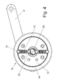
- FIG. 4 the coupling 9 is shown in the locked position.
- the locking means 15 can be disengaged from the drive wheel 14, so that the locking means 15 run on the inner circumference of the drive wheel 14.
- the force for triggering the clutch 9 corresponds to that force which is necessary for disengaging the two locking means 15 from the corresponding recesses 28.
- This force is dependent on the bias of the two springs 17, which act on the locking means 15.
- the spring force is variable via a control disk 20, against which the pressing pieces 16 rest on the inner side of the springs 17.
- the two springs 17 are compressed stronger or weaker, so that for moving out of the formed as fittings locking means 15 from the recesses 28 different amounts of force must be expended, depending on the position of the actuating arm. 2
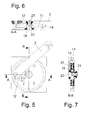
- the coupling 9 is shown in the assembled position.
- the drive wheel 14 and the output gear 11 are arranged adjacent to each other, so that results in a compact design.
- control disk 20 is shown in detail.
- the control disk is fixed about a central opening 22 on the axis 19, wherein the cam-shaped control curve 20 has regions with different radii R1 and R2.
- the cam-shaped control curve 20 has regions with different radii R1 and R2.
- R1 and R2 When an area having a larger radius R2 engages with the radially inner pressing pieces 16, the springs 17 are more compressed and the force for triggering the coupling 9 is greater than in areas having a smaller radius R1.
- the control disk 20 can be used over a certain angular range, but also a circumferential operation over a revolution of the driven wheel 11 addition is possible.
- FIG. 8B is a modified embodiment of a control cam 20 'is shown, in which in one area a corner 23 is formed. This allows a relatively abrupt change in the force curve for triggering the clutch 9 depending on the position of the actuating arm 2.
- the corner 23 may also form the boundary of the useful range of the control cam 20 '.
- FIG. 8C a modified cam 20 "is shown, which instead of a cam-shaped curve has a straight portion 25, a corner portion 24, and a curved course 26.
- control cam 20, 20 'and 20 can be selected depending on the particular application in order to set the desired force to trigger the clutch 9 depending on the position of the actuating arm 2.
- the drive wheel 14 is shown in detail, which has an outer toothing 27 which is in engagement with a gear of the transmission 8.
- an outer toothing 27 which is in engagement with a gear of the transmission 8.
- two opposing arcuate recesses 28 are provided, which form-fitting with the outer periphery the latching means 15 may be formed. But it is also possible to design the curvature of the locking means 15 and the recesses 28 deviating.
- FIG. 10 3 shows a modified embodiment of a drive wheel 14 ", in which triangular recesses are provided on the inner circumference, into which correspondingly angularly shaped latching means 15" are inserted, resulting in a sliding surface on each latching means which is provided with a sliding surface on the drive wheel 14 ". interacts.
- the coupling 9 may be formed as in the previous embodiments.
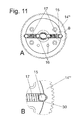
- a further embodiment of a drive wheel 14 ''' is shown, in which the detent means 15 designed as a bolt in a substantially V-shaped recess on the inner circumference of the drive wheel 14''' by the force of a spring 17 is held.
- a rounded transition 30 is formed, which allows a sliding movement when disengaging the locking means 15. As a result, a strong wear, as occurs at edge-shaped transitions, avoided.
- the radius of the transition 30 may be formed, for example, greater than 2mm, preferably greater than 4mm.
- two locking means 15 are biased by a spring 17 respectively. It is of course also possible to provide only one locking means 15 on the drive wheel 14. In addition, more than two locking means 15 may be provided for the trigger mechanism.
- control cam 20 is arranged on the inside of the output gear 11. It is of course also possible to provide a corresponding control cam on the outer circumference and to drive the drive wheel on the inside.
- the drive 5 can also be directly in engagement with the clutch 9 and, if necessary, a transmission between the clutch 9 and actuator arm 2 can be provided.
Landscapes
- Engineering & Computer Science (AREA)
- General Engineering & Computer Science (AREA)
- Mechanical Engineering (AREA)
- Mechanical Operated Clutches (AREA)
- Power-Operated Mechanisms For Wings (AREA)
- Hinges (AREA)
- Closing And Opening Devices For Wings, And Checks For Wings (AREA)
Abstract
Description
- Die vorliegende Erfindung betrifft einen angetriebenen Beschlag, insbesondere einen Klappenbeschlag für Möbel, mit mindestens einem Stellarm zum Öffnen und Schließen eines bewegbaren Möbelteils, und einem Antrieb zum Bewegen des Stellarmes, wobei zwischen Stellarm und Antrieb eine Kupplung angeordnet ist, die eine Bewegung des Stellarmes auch unabhängig von dem Antrieb ermöglicht.
- Die
WO 2006/099645 offenbart einen Klappenbeschlag für ein Möbel, bei dem eine Klappe über einen verschwenkbaren Stellarm bewegbar ist. Der Stellarm ist dabei durch eine Feder vorgespannt und durch einen elektrischen Antrieb bewegbar. Zwischen dem Stellarm und dem Antrieb ist eine Kupplungsvorrichtung wirksam, die zumindest in einer Drehrichtung über einen begrenzten Drehwinkelbereich einen Freilauf zum freien Bewegen des Stellarmes ermöglicht. Dadurch kann die Klappe über einen vorbestimmten Drehwinkelbereich auch von Hand betätigt werden. Nachteilig bei diesem Klappenbeschlag ist, dass der Drehwinkelbereich abhängig vom Einsatzfall variieren sollte und gerade bei einem Klappenbeschlag unterschiedliche Kräfte auf den Stellarm wirken. Dadurch kann das zum Entkuppeln der Kupplungsvorrichtung erforderliche Auslösemoment abhängig von der Position des Stellarmes sein, wobei eine optimierte Anpassung für den Benutzer nicht möglich ist. - Es ist daher Aufgabe der vorliegenden Erfindung einen angetriebenen Beschlag zu schaffen, der auch manuell betätigbar ist und in der Handhabung verbessert ist.
- Diese Aufgabe wird mit einem angetriebenen Beschlag mit den Merkmalen des Anspruches 1 gelöst.
- Erfindungsgemäß ist die Kraft zum Auskuppeln der Kupplung zwischen dem Stellarm und dem Antrieb abhängig von der Position des Stellarmes verstellbar, so dass das Auskuppeln der Kupplung an die mögliche manuelle Betätigung durch den Benutzer angepasst ist. Dabei ist es möglich, die Kraft zum Auskuppeln der Kupplung an die Anforderungen des sich bewegenden Stellarmes anzupassen, wobei der Auslösemechanismus für das Auskuppeln der Kupplung von anderen Einflüssen, wie einer Gewichtskraft eines verschwenkten Möbelteils entkoppelt werden kann. Dies lässt eine optimierte Anpassung des Auslösemechanismusses an die jeweilige Position des Stellarmes zu. Die Kraft zum Auskuppeln der Kupplung kann dabei über den gesamten Verstellweg konstant eingestellt bleiben, oder man kann z.B. bei einem geschlossenen Möbelteil die Kraft zum Auskuppeln der Kupplung sehr gering einstellen, da eine versehentliche Betätigung unwahrscheinlich ist.
- Gemäß einer bevorzugten Ausgestaltung der Erfindung ist die Kupplung als Rastkupplung ausgebildet und die Rastmittel lassen sich abhängig von der Position des Stellarmes mit unterschiedlicher Kraft außer Eingriff bringen. Dabei können die Rastmittel über eine Feder in die eingerastete Position vorgespannt sein, wobei die Federkraft zum Vorspannen der Rastmittel veränderbar ist. Dies ermöglicht eine optimale Einstellung des Auslösemechanismusses der Kupplung, der abhängig von dem jeweiligen Einsatzzweck ausgestaltet werden kann.
- Ein mechanisch zuverlässiger Auslösemechanismus kann eine Steuerkurve aufweisen, die mit dem Stellarm gekoppelt ist, um die Kraft zum Auslösen der Rastmittel zu verändern. Die Steuerkurve kann dabei abhängig von der Position des Stellarmes die Vorspannung der Rastmittel ändern.
- Vorzugsweise weist die Kupplung ein Antriebsrad und ein Abtriebsrad auf, zwischen den ein oder mehrere über Federn vorgespannte Rastmittel angeordnet sind, was auch eine kompakte Bauweise ergibt. Dabei kann eine Steuerkurve ortsfest angeordnet sein, wobei das Abtriebsrad und/oder das Antriebsrad relativ zu der Steuerkurve bewegbar ist. Nach dem Auskuppeln kann dann zu einem späteren Zeitpunkt der Antrieb eingeschaltet werden und ermöglicht so ein Einrasten der Rastmittel für eine nachfolgende motorische Betätigung.
- Vorzugsweise ist die Steuerkurve nockenförmig ausgebildet und kann aufgrund der unterschiedlichen Radien die Federn axial bewegen.
- Die Rastmittel können vorzugsweise bolzenförmig ausgebildet sein, die jeweils teilweise in eine Aussparung einfügbar sind. Auch andere Formen von Rastmitteln mit einer ebenen Gleitfläche können eingesetzt werden.
- In einer weiteren Ausgestaltung ist an der Aussparung benachbart zu dem Rastmittel ein gerundeter Übergang für ein sanfteres Ausrasten der Kupplung angeordnet. Dadurch wird beim Auskuppeln des Rastmittels eine gleitende Bewegung ermöglicht und eine starke Abnutzung, wie sie bei kantenförmigen Übergängen auftritt, vermieden.
- Die Erfindung wird nachfolgend anhand mehrerer Ausführungsbeispiele mit Bezug auf die beigefügten Zeichnungen näher erläutert. Es zeigen:
- Figur 1
- eine perspektivische Ansicht eines erfindungsgemäßen Beschlages;
- Figur 2
- eine Explosionsdarstellung des Beschlages der
Figur 1 ; - Figur 3
- eine Explosionsdarstellung der Kupplung des Beschlages der
Figur 1 ; - Figur 4
- eine Unteransicht der Kupplung der
Figur 3 ohne Deckel; - Figuren 5 bis 7
- mehrere Ansichten der erfindungsgemäßen Kupplung des Beschlages;
- Figuren 8A bis 8C
- unterschiedliche Ausführungsformen einer Steuerkurve des Beschlages;
- Figuren 9A + 9B
- unterschiedliche Ausführungsformen eines Antriebsrades für den Beschlag der
Figur 1 ; - Figur 10
- eine modifizierte Ausführungsform einer Kupplung des Beschlages, und
- Figuren 11A + 11B
- eine weitere Ausführungsform einer Kupplung des Beschlages.
- Ein Beschlag 1, insbesondere ein Klappenbeschlag umfasst einen Stellarm 2, der über eine Hebelmechanik 3 ein bewegbares Möbelteil, wie eine Klappe 4 verschwenken kann. Der Stellarm 2 ist über einen Antrieb 5, beispielsweise einen Elektromotor bewegbar. Der Antrieb 5 ist an einer Montageplatte 6 festgelegt, die an einem Möbelkorpus 7 montiert ist. Der Antrieb 5 treibt zunächst ein aus mehreren Zahnrädern gebildetes Getriebe 8 an, das über eine Kupplung 9 mit dem Stellarm 2 verbunden ist. Ferner ist eine Feder 10 vorgesehen, die die Klappe 4 in die geöffnete Position vorspannen kann, damit ein Teil der Gewichtskräfte der Klappe 4 in einer Offenstellung kompensiert werden.
- Die Kupplung 9 ermöglicht eine Entkopplung einer Bewegung des Stellarmes 2 von dem Antrieb 5. Dadurch ist es möglich, die Klappe 4 sowohl motorisch als auch manuell zu bewegen. Denn eine manuelle Betätigung ist z.B. dann erforderlich, wenn der Antrieb 5 in Folge von Stromausfall ausfällt, ein Widerstand im Schwenkbereich der Klappe 4 vorhanden ist oder der Benutzer die Klappe 4 gegenüber dem Antrieb 5 schneller öffnen möchte.
- In
Figur 3 ist die Kupplung 9 im Detail dargestellt. Die Kupplung 9 umfasst ein Abtriebsrad 11, an dem eine Verbindungsplatte 12 festgelegt ist, an der der Stellarm 2 drehbar angelenkt ist. Der Stellarm 2 ist dabei beabstandet von einer Drehachse des Abtriebrades 11 angeordnet. - In dem Abtriebsrad 11 ist eine Aufnahme 13 für einen Auslösemechanismus der Kupplung 9 vorgesehen. Der Auslösemechanismus ermöglicht eine Entkopplung eines Antriebsrades 14, das über Rastmittel 15 mit dem Abtriebsrad 11 gekoppelt ist. Die als Formstücke ausgebildeten Rastmittel 15 sind dabei über Federn 17 gegen eine Aussparung 28 an dem inneren Umfang des Antriebsrades 14 gedrückt gehalten. Am zur Achse 19 gerichteten Ende sind die Federn 17 über jeweils ein Druckstück 16 lagefixiert. Die Rastmittel 15 und Druckstücke 16 sowie die Feder 17 sind in der Aufnahme 13 an dem Abtriebsrad 11 geführt. Die Druckstücke 16 können bei entsprechender Gestaltung der Feder 17 auch weggelassen werden. Auf der zum Abtriebsrad 11 gegenüberliegenden Seite ist ein Deckel 18 vorgesehen, der mehrere Öffnungen aufweist und durch den eine Achse 19 geführt ist, an der eine Steuerkurve 20 montiert ist bzw. die integral mit der Achse 19 ausgebildet ist. Dabei ist die Achse 19 an der Montageplatte 6 festgelegt ist.
- Weitere Lagerstellen der beidseitigen Lagerungen der Getriebezahnräder und auch der Achse 19 können in der nicht dargestellten Getriebeabdeckung angeordnet sein.
- In
Figur 4 ist die Kupplung 9 in der eingerasteten Position dargestellt. Bei Drehen des Antriebsrades 14 wird über die Kopplung mit den bolzenförmigen Rastmitteln 15 auch das Abtriebsrad 11 und damit der Stellarm 2 bewegt. Sollte das bewegbare Möbelteil 4 manuell betätigt werden, können die Rastmittel 15 außer Eingriff mit dem Antriebsrad 14 gebracht werden, so dass die Rastmittel 15 am inneren Umfang des Antriebsrades 14 laufen. Die Kraft zum Auslösen der Kupplung 9 entspricht dabei derjenigen Kraft, die zum außer Eingriff bringen der beiden Rastmittel 15 aus den entsprechenden Aussparungen 28 notwendig ist. Diese Kraft ist abhängig von der Vorspannung der beiden Federn 17, die auf die Rastmittel 15 wirken. Dabei ist die Federkraft über eine Steuerscheibe 20 veränderbar, an der die Drückstücke 16 auf der inneren Seite der Federn 17 anliegen. Abhängig von der Position des Stellarmes 2 werden die beiden Federn 17 stärker oder schwächer zusammengedrückt, so dass zum Herausbewegen der als Formstücke ausgebildeten Rastmittel 15 aus den Aussparungen 28 unterschiedlich viel Kraft aufgewendet werden muss, abhängig von der Position des Stellarmes 2. - In den
Figuren 5 bis 7 ist die Kupplung 9 in der zusammengebauten Position gezeigt. Das Antriebsrad 14 und das Abtriebsrad 11 sind benachbart zueinander angeordnet, so dass sich ein kompakter Aufbau ergibt. - In
Figur 8A ist die Steuerscheibe 20 im Detail dargestellt. Die Steuerscheibe ist um eine mittige Öffnung 22 an der Achse 19 festgelegt, wobei die nockenförmige Steuerkurve 20 Bereiche mit unterschiedlichen Radien R1 und R2 aufweist. Wenn ein Bereich mit einem größeren Radius R2 in Eingriff mit den radial innen liegenden Drückstücken 16 gelangt, werden die Federn 17 stärker zusammengedrückt und die Kraft zum Auslösen der Kupplung 9 ist größer als in Bereichen mit einem kleineren Radius R1. Die Steuerscheibe 20 kann dabei über einen bestimmten Winkelbereich genutzt werden, aber auch ein umlaufender Betrieb über eine Umdrehung des Abtriebsrades 11 hinaus ist möglich. - In
Figur 8B ist eine modifizierte Ausführungsform einer Steuerkurve 20' dargestellt, bei der in einem Bereich eine Ecke 23 ausgebildet ist. Dies ermöglicht eine relativ sprunghafte Änderung des Kraftverlaufes zum Auslösen der Kupplung 9 abhängig von der Position des Stellarmes 2. Die Ecke 23 kann auch die Begrenzung des Nutzbereiches der Steuerkurve 20' bilden. Durch eine rotationssymmetrische Ausbildung kann die Kraft gegenüberliegender Federn 17 im Gleichlauf verändert werden. - In
Figur 8C ist eine modifizierte Steuerkurve 20" dargestellt, die statt einer nockenförmigen Kurve einen geraden Abschnitt 25, einen Eckbereich 24, sowie einen bogenförmigen Verlauf 26 aufweist. - Die Geometrie der Steuerkurve 20, 20' und 20" kann abhängig von dem jeweiligen Einsatzzweck gewählt werden, um die gewünschte Kraft zum Auslösen der Kupplung 9 abhängig von der Position des Stellarmes 2 einstellen zu können.
- In
Figur 9A ist das Antriebsrad 14 im Detail dargestellt, das eine äußere Verzahnung 27 aufweist, die in Eingriff mit einem Zahnrad des Getriebes 8 ist. An einem inneren Umfang des Antriebsrades 14 sind zwei sich gegenüberliegende bogenförmige Aussparungen 28 vorgesehen, die formschlüssig mit dem äußeren Umfang der Rastmittel 15 ausgebildet sein können. Es ist aber auch möglich, die Krümmung der Rastmittel 15 und der Aussparungen 28 abweichend auszugestalten. - Bei dem in
Figur 9B gezeigten modifizierten Ausführungsbeispiel eines Antriebsrades 14' sind dreieckförmige Aussparungen 29 vorgesehen, die eine geringere Tiefe aufweisen und daher leichter zu entkoppeln sind. - In
Figur 10 ist eine modifizierte Ausführungsform eines Antriebsrades 14" gezeigt, bei dem dreieckförmige Aussparungen am inneren Umfang vorgesehen sind, in die entsprechend winkelförmig geformte Rastmittel 15'' eingefügt sind. Dadurch ergibt sich eine Gleitfläche an jedem Rastmittel, die mit einer Gleitfläche an dem Antriebsrad 14" zusammenwirkt. Im übrigen kann die Kupplung 9 wie bei dem vorangegangenen Ausführungsbeispielen ausgebildet sein. - In den
Figuren 11A und 11B ist eine weitere Ausführungsform eines Antriebsrades 14''' dargestellt, bei der die als Bolzen ausgebildeten Rastmittel 15 in einer im wesentlichen V-förmigen Aussparung am inneren Umfang des Antriebsrades 14''' durch die Kraft einer Feder 17 gehalten ist. Zwischen der Aussparung und dem inneren Umfang an dem Antriebsrad 14''' ist ein gerundeter Übergang 30 ausgebildet, der beim Auskuppeln des Rastmittels 15 eine gleitende Bewegung zulässt. Dadurch wird eine starke Abnutzung, wie sie bei kantenförmigen Übergängen auftritt, vermieden. Der Radius des Überganges 30 kann z.B. größer als 2mm, vorzugsweise größer als 4mm ausgebildet sein. - In den dargestellten Ausführungsbeispielen sind jeweils zwei Rastmittel 15 über eine Feder 17 vorgespannt. Es ist natürlich auch möglich, nur ein Rastmittel 15 an dem Antriebsrad 14 vorzusehen. Zudem können auch mehr als zwei Rastmittel 15 für den Auslösemechanismus vorgesehen werden.
- In dem dargestellten Ausführungsbeispiel ist die Steuerkurve 20 innen an dem Abtriebsrad 11 angeordnet. Es ist natürlich auch möglich, am äußeren Umfang eine entsprechende Steuerkurve vorzusehen und das Antriebsrad an der Innenseite anzutreiben.
- Zudem kann der Antrieb 5 auch unmittelbar mit der Kupplung 9 in Eingriff stehen und bei Bedarf kann ein Getriebe zwischen Kupplung 9 und Stellarm 2 vorgesehen sein.
Claims (10)
- Angetriebener Beschlag (1), insbesondere Klappenbeschlag für Möbel, mit mindestens einem Stellarm (2) zum Öffnen und Schließen eines bewegbaren Möbelteils (4), und einem Antrieb (5) zum Bewegen des Stellarmes (2), wobei zwischen Stellarm (2) und Antrieb (5) eine Kupplung (9) angeordnet ist, die eine Bewegung des Stellarmes (2) auch unabhängig von dem Antrieb (5) ermöglicht, dadurch gekennzeichnet, dass die Kraft zum Auskuppeln der Kupplung (9) abhängig von der Position des Stellarmes (2) verstellbar ist.
- Beschlag nach Anspruch 1, dadurch gekennzeichnet, dass die Kupplung (9) als Rastkupplung ausgebildet ist und die Rastmittel (15) sich abhängig von der Position des Stellarmes (2) mit unterschiedlicher Kraft außer Eingriff bringen lassen.
- Beschlag nach Anspruch 2, dadurch gekennzeichnet, dass die Rastmittel (15) über eine Feder (17) in die eingerastete Position vorgespannt sind.
- Beschlag nach Anspruch 2 oder 3, dadurch gekennzeichnet, dass die Federkraft zum Vorspannen der Rastmittel (15) veränderbar ist.
- Beschlag nach einem der Ansprüche 1 bis 4, dadurch gekennzeichnet, dass eine Steuerkurve (20) mit dem Stellarm (2) gekoppelt ist, um die Kraft zum Auskuppeln der Rastmittel (15) zu verändern.
- Beschlag nach einem der Ansprüche 1 bis 5, dadurch gekennzeichnet, dass die Kupplung (9) ein Antriebsrad (14) und ein Abtriebsrad (11) aufweist, zwischen den ein oder mehrere über Federn (17) vorgespannte Rastmittel (15) angeordnet sind.
- Beschlag nach Anspruch 6, dadurch gekennzeichnet, dass eine Steuerkurve (20) ortsfest angeordnet ist, und/oder das Abtriebsrad (11) und/oder dem Antriebsrad (14) relativ zu der Steuerkurve (20) bewegbar ist.
- Beschlag nach einem der Ansprüche 1 bis 7, dadurch gekennzeichnet, dass die Steuerkurve (20) nockenförmig ausgebildet ist.
- Beschlag nach einem der Ansprüche 1 bis 8, dadurch gekennzeichnet, dass die Rastmittel (15) bolzenförmig ausgebildet sind, die jeweils teilweise in eine Aussparung (28) an dem Antriebsrad (14) einfügbar sind.
- Beschlag nach einem der Ansprüche 1 bis 9, dadurch gekennzeichnet, dass an der Aussparung benachbart zu dem Rastmittel (15) ein gerundeter Übergang (30) für ein sanfteres Ausrasten der Kupplung angeordnet ist.
Applications Claiming Priority (1)
| Application Number | Priority Date | Filing Date | Title |
|---|---|---|---|
| DE202007014560U DE202007014560U1 (de) | 2007-10-16 | 2007-10-16 | Angetriebener Beschlag |
Publications (3)
| Publication Number | Publication Date |
|---|---|
| EP2050911A2 true EP2050911A2 (de) | 2009-04-22 |
| EP2050911A3 EP2050911A3 (de) | 2013-12-04 |
| EP2050911B1 EP2050911B1 (de) | 2015-06-24 |
Family
ID=40174784
Family Applications (1)
| Application Number | Title | Priority Date | Filing Date |
|---|---|---|---|
| EP08162964.4A Active EP2050911B1 (de) | 2007-10-16 | 2008-08-26 | Angetriebener Beschlag |
Country Status (5)
| Country | Link |
|---|---|
| EP (1) | EP2050911B1 (de) |
| JP (1) | JP5380666B2 (de) |
| DE (1) | DE202007014560U1 (de) |
| ES (1) | ES2546942T3 (de) |
| RU (1) | RU2505655C2 (de) |
Cited By (6)
| Publication number | Priority date | Publication date | Assignee | Title |
|---|---|---|---|---|
| EP2248981A1 (de) * | 2009-05-08 | 2010-11-10 | Hetal-Werke Franz Hettich GmbH & Co. KG | Klappenbeschlag für eine Möbelklappe und Möbel |
| DE202010016154U1 (de) | 2010-11-25 | 2012-02-29 | Grass Gmbh | Bewegungsvorrichtung für ein bewegliches Möbelteil |
| DE202010016153U1 (de) | 2010-11-25 | 2012-02-29 | Grass Gmbh | Bewegungsvorrichtung für ein bewegliches Möbelteil |
| DE202012009451U1 (de) * | 2012-10-01 | 2014-01-07 | Hetal-Werke Franz Hettich Gmbh & Co. Kg | Bewegungsvorrichtung für ein bewegbares Möbelteil |
| US9624709B2 (en) | 2009-05-13 | 2017-04-18 | Julius Blum Gmbh | Flap drive system |
| WO2024050580A1 (de) * | 2022-09-09 | 2024-03-14 | Julius Blum Gmbh | Möbelantrieb zum antreiben eines bewegbaren möbelteils |
Families Citing this family (4)
| Publication number | Priority date | Publication date | Assignee | Title |
|---|---|---|---|---|
| DE202010016982U1 (de) * | 2010-12-23 | 2012-04-02 | Grass Gmbh | Bewegungsvorrichtung |
| FR3031150B1 (fr) * | 2014-12-26 | 2018-05-11 | Compagnie Plastic Omnium | Organe de debrayage pour volet aerodynamique retractable de vehicule automobile |
| DE102021130104A1 (de) | 2021-11-18 | 2023-05-25 | Grass Gmbh | Kupplung mit einem Antrieb, einem Abtrieb und einer Sperrklinke |
| DE102024115834A1 (de) * | 2024-06-06 | 2025-12-11 | Flap Competence Center Kft | Hebelarm für einen möbelbeschlag zum gelenkigen verbinden eines bewegbaren möbelteils mit einem möbelkorpus |
Citations (1)
| Publication number | Priority date | Publication date | Assignee | Title |
|---|---|---|---|---|
| WO2006099645A1 (de) | 2005-03-21 | 2006-09-28 | Julius Blum Gmbh | Möbel |
Family Cites Families (7)
| Publication number | Priority date | Publication date | Assignee | Title |
|---|---|---|---|---|
| US1635758A (en) * | 1925-05-16 | 1927-07-12 | Henry B Crawford | Door-operating mechanism |
| US2912237A (en) * | 1957-06-06 | 1959-11-10 | Gen Motors Corp | Door operator |
| DE2757230A1 (de) * | 1977-12-22 | 1979-07-05 | Hettich Hetal Werke | Scharnier |
| DE3141534C2 (de) * | 1981-10-20 | 1984-03-22 | Bergwerksverband Gmbh, 4300 Essen | Überlastschutzkupplung mit federbelasteten Mitnehmern |
| AT403080B (de) * | 1995-02-06 | 1997-11-25 | Ife Gmbh | Antrieb für eine türe |
| DE10223026C5 (de) * | 2002-05-22 | 2007-11-08 | Huwil-Werke Gmbh Möbelschloss- Und Beschlagfabriken | Deckelsteller |
| DE102005055788B4 (de) * | 2005-11-21 | 2016-10-27 | Stabilus Gmbh | Betätigungseinrichtung für ein bewegliches Bauteil |
-
2007
- 2007-10-16 DE DE202007014560U patent/DE202007014560U1/de not_active Expired - Lifetime
-
2008
- 2008-08-26 ES ES08162964.4T patent/ES2546942T3/es active Active
- 2008-08-26 EP EP08162964.4A patent/EP2050911B1/de active Active
- 2008-09-26 JP JP2008248561A patent/JP5380666B2/ja not_active Expired - Fee Related
- 2008-10-15 RU RU2008140678/12A patent/RU2505655C2/ru not_active IP Right Cessation
Patent Citations (1)
| Publication number | Priority date | Publication date | Assignee | Title |
|---|---|---|---|---|
| WO2006099645A1 (de) | 2005-03-21 | 2006-09-28 | Julius Blum Gmbh | Möbel |
Cited By (8)
| Publication number | Priority date | Publication date | Assignee | Title |
|---|---|---|---|---|
| EP2248981A1 (de) * | 2009-05-08 | 2010-11-10 | Hetal-Werke Franz Hettich GmbH & Co. KG | Klappenbeschlag für eine Möbelklappe und Möbel |
| US9624709B2 (en) | 2009-05-13 | 2017-04-18 | Julius Blum Gmbh | Flap drive system |
| DE202010016154U1 (de) | 2010-11-25 | 2012-02-29 | Grass Gmbh | Bewegungsvorrichtung für ein bewegliches Möbelteil |
| DE202010016153U1 (de) | 2010-11-25 | 2012-02-29 | Grass Gmbh | Bewegungsvorrichtung für ein bewegliches Möbelteil |
| WO2012069141A1 (de) | 2010-11-25 | 2012-05-31 | Grass Gmbh | Bewegungsvorrichtung für ein bewegliches möbelteil |
| DE202012009451U1 (de) * | 2012-10-01 | 2014-01-07 | Hetal-Werke Franz Hettich Gmbh & Co. Kg | Bewegungsvorrichtung für ein bewegbares Möbelteil |
| EP2712997A3 (de) * | 2012-10-01 | 2017-12-20 | Hetal-Werke Franz Hettich GmbH & Co. KG | Bewegungsvorrichtung für ein bewegbares Möbelteil |
| WO2024050580A1 (de) * | 2022-09-09 | 2024-03-14 | Julius Blum Gmbh | Möbelantrieb zum antreiben eines bewegbaren möbelteils |
Also Published As
| Publication number | Publication date |
|---|---|
| JP5380666B2 (ja) | 2014-01-08 |
| ES2546942T3 (es) | 2015-09-30 |
| RU2505655C2 (ru) | 2014-01-27 |
| EP2050911A3 (de) | 2013-12-04 |
| DE202007014560U1 (de) | 2009-03-12 |
| JP2009114844A (ja) | 2009-05-28 |
| RU2008140678A (ru) | 2010-04-20 |
| EP2050911B1 (de) | 2015-06-24 |
Similar Documents
| Publication | Publication Date | Title |
|---|---|---|
| EP2050911B1 (de) | Angetriebener Beschlag | |
| DE602004009688T2 (de) | Ventilantriebsmechanismus | |
| EP2098743B1 (de) | Stellmechanismus zum Ein- und Ausrücken einer Trennkupplung mit drehbarem Kurvensegment | |
| EP1962738B1 (de) | Schaltkupplung für prothesen | |
| DE10196484B4 (de) | Vorrichtung zum Sperren der Zahnräder einer Kraftübertragung | |
| EP2217783B1 (de) | Antriebssytem für ein verschliessteil eines kraftfahrzeugs | |
| WO2008019641A1 (de) | Drehschwingungsdämpfer | |
| AT524391A1 (de) | Möbelantrieb zum Bewegen eines relativ zu einem Möbelkorpus bewegbar gelagerten Möbelteiles | |
| EP2145118A1 (de) | Drehmomenten-/drehzahldifferenzabhängige kupplungsbetätigungseinheit für motorangetriebene fahrzeuge | |
| EP2248981A1 (de) | Klappenbeschlag für eine Möbelklappe und Möbel | |
| DE3118634C2 (de) | Verstellantrieb mit Schlingfederbremselement in einem Kraftfahrzeug, insbesondere für einen Fensterheber | |
| DE19927033C2 (de) | Beidseitig wirkender Antrieb für Verstellvorrichtungen | |
| DE102009036872B4 (de) | Türeinheit | |
| EP4158138B1 (de) | Antriebseinheit für kraftfahrzeug-technische anwendungen | |
| DE3317191A1 (de) | Ventilaktuator | |
| DE102009005044B4 (de) | Verstellvorrichtung zum Verstellen eines Fahrzeugsitzteils | |
| EP4529582B1 (de) | Möbelantrieb zum bewegen eines relativ zu einem möbelkorpus bewegbar gelagerten möbelteiles | |
| DE102012220941A1 (de) | Betätigungssystem mit einem Hebelaktor | |
| EP1528194B1 (de) | Beschlag, insbesondere Fensterbeschlag | |
| EP1303430A1 (de) | Wischanlage | |
| AT406850B (de) | Antriebsvorrichtung für eine verschlusseinrichtung eines fahrzeugtank-einfüllstutzens | |
| EP2000690B1 (de) | Ausrückvorrichtung | |
| EP1914432A2 (de) | Sicherheitseinrichtung zur Vermeidung von Beschädigungen einer Vorrichtung zur Übertragung von Drehmomenten | |
| DE202019100595U1 (de) | Bremseinrichtung | |
| EP1179109A1 (de) | Kraftfahrzeug-türschloss |
Legal Events
| Date | Code | Title | Description |
|---|---|---|---|
| PUAI | Public reference made under article 153(3) epc to a published international application that has entered the european phase |
Free format text: ORIGINAL CODE: 0009012 |
|
| AK | Designated contracting states |
Kind code of ref document: A2 Designated state(s): AT BE BG CH CY CZ DE DK EE ES FI FR GB GR HR HU IE IS IT LI LT LU LV MC MT NL NO PL PT RO SE SI SK TR |
|
| AX | Request for extension of the european patent |
Extension state: AL BA MK RS |
|
| PUAL | Search report despatched |
Free format text: ORIGINAL CODE: 0009013 |
|
| AK | Designated contracting states |
Kind code of ref document: A3 Designated state(s): AT BE BG CH CY CZ DE DK EE ES FI FR GB GR HR HU IE IS IT LI LT LU LV MC MT NL NO PL PT RO SE SI SK TR |
|
| AX | Request for extension of the european patent |
Extension state: AL BA MK RS |
|
| RIC1 | Information provided on ipc code assigned before grant |
Ipc: F16D 7/10 20060101ALI20131030BHEP Ipc: E05F 15/12 20060101AFI20131030BHEP Ipc: E05D 15/46 20060101ALI20131030BHEP Ipc: F16D 43/208 20060101ALI20131030BHEP Ipc: E05D 3/16 20060101ALI20131030BHEP |
|
| 17P | Request for examination filed |
Effective date: 20140604 |
|
| RBV | Designated contracting states (corrected) |
Designated state(s): AT BE BG CH CY CZ DE DK EE ES FI FR GB GR HR HU IE IS IT LI LT LU LV MC MT NL NO PL PT RO SE SI SK TR |
|
| AKX | Designation fees paid |
Designated state(s): AT BE BG CH CY CZ DE DK EE ES FI FR GB GR HR HU IE IS IT LI LT LU LV MC MT NL NO PL PT RO SE SI SK TR |
|
| GRAP | Despatch of communication of intention to grant a patent |
Free format text: ORIGINAL CODE: EPIDOSNIGR1 |
|
| INTG | Intention to grant announced |
Effective date: 20150108 |
|
| GRAS | Grant fee paid |
Free format text: ORIGINAL CODE: EPIDOSNIGR3 |
|
| REG | Reference to a national code |
Ref country code: DE Ref legal event code: R079 Ref document number: 502008013071 Country of ref document: DE Free format text: PREVIOUS MAIN CLASS: E05F0015120000 Ipc: E05F0015611000 |
|
| GRAA | (expected) grant |
Free format text: ORIGINAL CODE: 0009210 |
|
| AK | Designated contracting states |
Kind code of ref document: B1 Designated state(s): AT BE BG CH CY CZ DE DK EE ES FI FR GB GR HR HU IE IS IT LI LT LU LV MC MT NL NO PL PT RO SE SI SK TR |
|
| REG | Reference to a national code |
Ref country code: GB Ref legal event code: FG4D Free format text: NOT ENGLISH |
|
| RIC1 | Information provided on ipc code assigned before grant |
Ipc: E05D 3/16 20060101ALI20150519BHEP Ipc: E05D 15/46 20060101ALI20150519BHEP Ipc: F16D 7/10 20060101ALI20150519BHEP Ipc: F16D 43/208 20060101ALI20150519BHEP Ipc: E05F 15/611 20150101AFI20150519BHEP |
|
| REG | Reference to a national code |
Ref country code: CH Ref legal event code: EP |
|
| REG | Reference to a national code |
Ref country code: AT Ref legal event code: REF Ref document number: 732956 Country of ref document: AT Kind code of ref document: T Effective date: 20150715 |
|
| REG | Reference to a national code |
Ref country code: IE Ref legal event code: FG4D Free format text: LANGUAGE OF EP DOCUMENT: GERMAN |
|
| REG | Reference to a national code |
Ref country code: DE Ref legal event code: R096 Ref document number: 502008013071 Country of ref document: DE |
|
| REG | Reference to a national code |
Ref country code: FR Ref legal event code: PLFP Year of fee payment: 8 |
|
| REG | Reference to a national code |
Ref country code: ES Ref legal event code: FG2A Ref document number: 2546942 Country of ref document: ES Kind code of ref document: T3 Effective date: 20150930 |
|
| PG25 | Lapsed in a contracting state [announced via postgrant information from national office to epo] |
Ref country code: FI Free format text: LAPSE BECAUSE OF FAILURE TO SUBMIT A TRANSLATION OF THE DESCRIPTION OR TO PAY THE FEE WITHIN THE PRESCRIBED TIME-LIMIT Effective date: 20150624 Ref country code: NO Free format text: LAPSE BECAUSE OF FAILURE TO SUBMIT A TRANSLATION OF THE DESCRIPTION OR TO PAY THE FEE WITHIN THE PRESCRIBED TIME-LIMIT Effective date: 20150924 Ref country code: LT Free format text: LAPSE BECAUSE OF FAILURE TO SUBMIT A TRANSLATION OF THE DESCRIPTION OR TO PAY THE FEE WITHIN THE PRESCRIBED TIME-LIMIT Effective date: 20150624 Ref country code: HR Free format text: LAPSE BECAUSE OF FAILURE TO SUBMIT A TRANSLATION OF THE DESCRIPTION OR TO PAY THE FEE WITHIN THE PRESCRIBED TIME-LIMIT Effective date: 20150624 |
|
| REG | Reference to a national code |
Ref country code: LT Ref legal event code: MG4D |
|
| PG25 | Lapsed in a contracting state [announced via postgrant information from national office to epo] |
Ref country code: GR Free format text: LAPSE BECAUSE OF FAILURE TO SUBMIT A TRANSLATION OF THE DESCRIPTION OR TO PAY THE FEE WITHIN THE PRESCRIBED TIME-LIMIT Effective date: 20150925 Ref country code: BG Free format text: LAPSE BECAUSE OF FAILURE TO SUBMIT A TRANSLATION OF THE DESCRIPTION OR TO PAY THE FEE WITHIN THE PRESCRIBED TIME-LIMIT Effective date: 20150924 Ref country code: LV Free format text: LAPSE BECAUSE OF FAILURE TO SUBMIT A TRANSLATION OF THE DESCRIPTION OR TO PAY THE FEE WITHIN THE PRESCRIBED TIME-LIMIT Effective date: 20150624 |
|
| REG | Reference to a national code |
Ref country code: NL Ref legal event code: MP Effective date: 20150624 |
|
| PG25 | Lapsed in a contracting state [announced via postgrant information from national office to epo] |
Ref country code: EE Free format text: LAPSE BECAUSE OF FAILURE TO SUBMIT A TRANSLATION OF THE DESCRIPTION OR TO PAY THE FEE WITHIN THE PRESCRIBED TIME-LIMIT Effective date: 20150624 |
|
| PG25 | Lapsed in a contracting state [announced via postgrant information from national office to epo] |
Ref country code: RO Free format text: LAPSE BECAUSE OF NON-PAYMENT OF DUE FEES Effective date: 20150624 Ref country code: PT Free format text: LAPSE BECAUSE OF FAILURE TO SUBMIT A TRANSLATION OF THE DESCRIPTION OR TO PAY THE FEE WITHIN THE PRESCRIBED TIME-LIMIT Effective date: 20151026 Ref country code: SK Free format text: LAPSE BECAUSE OF FAILURE TO SUBMIT A TRANSLATION OF THE DESCRIPTION OR TO PAY THE FEE WITHIN THE PRESCRIBED TIME-LIMIT Effective date: 20150624 Ref country code: PL Free format text: LAPSE BECAUSE OF FAILURE TO SUBMIT A TRANSLATION OF THE DESCRIPTION OR TO PAY THE FEE WITHIN THE PRESCRIBED TIME-LIMIT Effective date: 20150624 Ref country code: CZ Free format text: LAPSE BECAUSE OF FAILURE TO SUBMIT A TRANSLATION OF THE DESCRIPTION OR TO PAY THE FEE WITHIN THE PRESCRIBED TIME-LIMIT Effective date: 20150624 Ref country code: IS Free format text: LAPSE BECAUSE OF FAILURE TO SUBMIT A TRANSLATION OF THE DESCRIPTION OR TO PAY THE FEE WITHIN THE PRESCRIBED TIME-LIMIT Effective date: 20151024 |
|
| REG | Reference to a national code |
Ref country code: DE Ref legal event code: R097 Ref document number: 502008013071 Country of ref document: DE |
|
| RAP2 | Party data changed (patent owner data changed or rights of a patent transferred) |
Owner name: HETTICH-HEINZE GMBH & CO. KG |
|
| PG25 | Lapsed in a contracting state [announced via postgrant information from national office to epo] |
Ref country code: MC Free format text: LAPSE BECAUSE OF FAILURE TO SUBMIT A TRANSLATION OF THE DESCRIPTION OR TO PAY THE FEE WITHIN THE PRESCRIBED TIME-LIMIT Effective date: 20150624 Ref country code: LU Free format text: LAPSE BECAUSE OF FAILURE TO SUBMIT A TRANSLATION OF THE DESCRIPTION OR TO PAY THE FEE WITHIN THE PRESCRIBED TIME-LIMIT Effective date: 20150826 |
|
| REG | Reference to a national code |
Ref country code: CH Ref legal event code: PL |
|
| PG25 | Lapsed in a contracting state [announced via postgrant information from national office to epo] |
Ref country code: DK Free format text: LAPSE BECAUSE OF FAILURE TO SUBMIT A TRANSLATION OF THE DESCRIPTION OR TO PAY THE FEE WITHIN THE PRESCRIBED TIME-LIMIT Effective date: 20150624 Ref country code: CH Free format text: LAPSE BECAUSE OF NON-PAYMENT OF DUE FEES Effective date: 20150831 Ref country code: LI Free format text: LAPSE BECAUSE OF NON-PAYMENT OF DUE FEES Effective date: 20150831 |
|
| PLBE | No opposition filed within time limit |
Free format text: ORIGINAL CODE: 0009261 |
|
| STAA | Information on the status of an ep patent application or granted ep patent |
Free format text: STATUS: NO OPPOSITION FILED WITHIN TIME LIMIT |
|
| 26N | No opposition filed |
Effective date: 20160329 |
|
| REG | Reference to a national code |
Ref country code: IE Ref legal event code: MM4A |
|
| PG25 | Lapsed in a contracting state [announced via postgrant information from national office to epo] |
Ref country code: IE Free format text: LAPSE BECAUSE OF NON-PAYMENT OF DUE FEES Effective date: 20150826 |
|
| REG | Reference to a national code |
Ref country code: FR Ref legal event code: PLFP Year of fee payment: 9 |
|
| PG25 | Lapsed in a contracting state [announced via postgrant information from national office to epo] |
Ref country code: SI Free format text: LAPSE BECAUSE OF FAILURE TO SUBMIT A TRANSLATION OF THE DESCRIPTION OR TO PAY THE FEE WITHIN THE PRESCRIBED TIME-LIMIT Effective date: 20150624 |
|
| PG25 | Lapsed in a contracting state [announced via postgrant information from national office to epo] |
Ref country code: MT Free format text: LAPSE BECAUSE OF FAILURE TO SUBMIT A TRANSLATION OF THE DESCRIPTION OR TO PAY THE FEE WITHIN THE PRESCRIBED TIME-LIMIT Effective date: 20150624 |
|
| PG25 | Lapsed in a contracting state [announced via postgrant information from national office to epo] |
Ref country code: HU Free format text: LAPSE BECAUSE OF FAILURE TO SUBMIT A TRANSLATION OF THE DESCRIPTION OR TO PAY THE FEE WITHIN THE PRESCRIBED TIME-LIMIT; INVALID AB INITIO Effective date: 20080826 |
|
| PG25 | Lapsed in a contracting state [announced via postgrant information from national office to epo] |
Ref country code: CY Free format text: LAPSE BECAUSE OF FAILURE TO SUBMIT A TRANSLATION OF THE DESCRIPTION OR TO PAY THE FEE WITHIN THE PRESCRIBED TIME-LIMIT Effective date: 20150624 Ref country code: SE Free format text: LAPSE BECAUSE OF FAILURE TO SUBMIT A TRANSLATION OF THE DESCRIPTION OR TO PAY THE FEE WITHIN THE PRESCRIBED TIME-LIMIT Effective date: 20150624 Ref country code: NL Free format text: LAPSE BECAUSE OF FAILURE TO SUBMIT A TRANSLATION OF THE DESCRIPTION OR TO PAY THE FEE WITHIN THE PRESCRIBED TIME-LIMIT Effective date: 20150624 |
|
| PG25 | Lapsed in a contracting state [announced via postgrant information from national office to epo] |
Ref country code: BE Free format text: LAPSE BECAUSE OF NON-PAYMENT OF DUE FEES Effective date: 20150831 |
|
| REG | Reference to a national code |
Ref country code: FR Ref legal event code: PLFP Year of fee payment: 10 |
|
| REG | Reference to a national code |
Ref country code: FR Ref legal event code: PLFP Year of fee payment: 11 |
|
| PGFP | Annual fee paid to national office [announced via postgrant information from national office to epo] |
Ref country code: FR Payment date: 20190822 Year of fee payment: 12 |
|
| PGFP | Annual fee paid to national office [announced via postgrant information from national office to epo] |
Ref country code: GB Payment date: 20190827 Year of fee payment: 12 |
|
| GBPC | Gb: european patent ceased through non-payment of renewal fee |
Effective date: 20200826 |
|
| PG25 | Lapsed in a contracting state [announced via postgrant information from national office to epo] |
Ref country code: FR Free format text: LAPSE BECAUSE OF NON-PAYMENT OF DUE FEES Effective date: 20200831 |
|
| PG25 | Lapsed in a contracting state [announced via postgrant information from national office to epo] |
Ref country code: GB Free format text: LAPSE BECAUSE OF NON-PAYMENT OF DUE FEES Effective date: 20200826 |
|
| REG | Reference to a national code |
Ref country code: DE Ref legal event code: R084 Ref document number: 502008013071 Country of ref document: DE |
|
| PGFP | Annual fee paid to national office [announced via postgrant information from national office to epo] |
Ref country code: ES Payment date: 20210917 Year of fee payment: 14 |
|
| P01 | Opt-out of the competence of the unified patent court (upc) registered |
Effective date: 20230403 |
|
| REG | Reference to a national code |
Ref country code: ES Ref legal event code: FD2A Effective date: 20230929 |
|
| PG25 | Lapsed in a contracting state [announced via postgrant information from national office to epo] |
Ref country code: ES Free format text: LAPSE BECAUSE OF NON-PAYMENT OF DUE FEES Effective date: 20220827 |
|
| PGFP | Annual fee paid to national office [announced via postgrant information from national office to epo] |
Ref country code: AT Payment date: 20240819 Year of fee payment: 17 |
|
| PGFP | Annual fee paid to national office [announced via postgrant information from national office to epo] |
Ref country code: IT Payment date: 20240830 Year of fee payment: 17 |
|
| PGFP | Annual fee paid to national office [announced via postgrant information from national office to epo] |
Ref country code: TR Payment date: 20240819 Year of fee payment: 17 |
|
| PGFP | Annual fee paid to national office [announced via postgrant information from national office to epo] |
Ref country code: DE Payment date: 20250819 Year of fee payment: 18 |
|
| PG25 | Lapsed in a contracting state [announced via postgrant information from national office to epo] |
Ref country code: AT Free format text: LAPSE BECAUSE OF NON-PAYMENT OF DUE FEES Effective date: 20250826 |
|
| REG | Reference to a national code |
Ref country code: AT Ref legal event code: MM01 Ref document number: 732956 Country of ref document: AT Kind code of ref document: T Effective date: 20250826 |