EP2050947A2 - Dichtungselement und Dichtungsstruktur - Google Patents
Dichtungselement und Dichtungsstruktur Download PDFInfo
- Publication number
- EP2050947A2 EP2050947A2 EP08018007A EP08018007A EP2050947A2 EP 2050947 A2 EP2050947 A2 EP 2050947A2 EP 08018007 A EP08018007 A EP 08018007A EP 08018007 A EP08018007 A EP 08018007A EP 2050947 A2 EP2050947 A2 EP 2050947A2
- Authority
- EP
- European Patent Office
- Prior art keywords
- connecting element
- cylinder head
- sealing member
- seal
- head cover
- Prior art date
- Legal status (The legal status is an assumption and is not a legal conclusion. Google has not performed a legal analysis and makes no representation as to the accuracy of the status listed.)
- Withdrawn
Links
- 238000007789 sealing Methods 0.000 title claims abstract description 80
- 238000005192 partition Methods 0.000 claims description 10
- 238000003780 insertion Methods 0.000 description 15
- 230000037431 insertion Effects 0.000 description 15
- 239000003921 oil Substances 0.000 description 12
- 235000001674 Agaricus brunnescens Nutrition 0.000 description 3
- 239000010687 lubricating oil Substances 0.000 description 3
- 230000002093 peripheral effect Effects 0.000 description 3
- 238000004519 manufacturing process Methods 0.000 description 2
- 239000002184 metal Substances 0.000 description 2
- 238000000034 method Methods 0.000 description 2
- 238000000465 moulding Methods 0.000 description 2
- 244000025254 Cannabis sativa Species 0.000 description 1
- 229920000800 acrylic rubber Polymers 0.000 description 1
- 230000006866 deterioration Effects 0.000 description 1
- 239000013013 elastic material Substances 0.000 description 1
- 239000000835 fiber Substances 0.000 description 1
- 229920001973 fluoroelastomer Polymers 0.000 description 1
- 239000000463 material Substances 0.000 description 1
- 229920000058 polyacrylate Polymers 0.000 description 1
- 239000012779 reinforcing material Substances 0.000 description 1
- 229920002379 silicone rubber Polymers 0.000 description 1
- 239000004945 silicone rubber Substances 0.000 description 1
Images




Classifications
-
- F—MECHANICAL ENGINEERING; LIGHTING; HEATING; WEAPONS; BLASTING
- F16—ENGINEERING ELEMENTS AND UNITS; GENERAL MEASURES FOR PRODUCING AND MAINTAINING EFFECTIVE FUNCTIONING OF MACHINES OR INSTALLATIONS; THERMAL INSULATION IN GENERAL
- F16J—PISTONS; CYLINDERS; SEALINGS
- F16J15/00—Sealings
- F16J15/02—Sealings between relatively-stationary surfaces
- F16J15/06—Sealings between relatively-stationary surfaces with solid packing compressed between sealing surfaces
- F16J15/061—Sealings between relatively-stationary surfaces with solid packing compressed between sealing surfaces with positioning means
-
- F—MECHANICAL ENGINEERING; LIGHTING; HEATING; WEAPONS; BLASTING
- F02—COMBUSTION ENGINES; HOT-GAS OR COMBUSTION-PRODUCT ENGINE PLANTS
- F02F—CYLINDERS, PISTONS OR CASINGS, FOR COMBUSTION ENGINES; ARRANGEMENTS OF SEALINGS IN COMBUSTION ENGINES
- F02F7/00—Casings, e.g. crankcases
- F02F7/006—Camshaft or pushrod housings
Definitions
- the present invention relates to a sealing member and a sealing structure, and more particularly relates to a sealing member that is provided between a cylinder head and a cylinder head cover of an engine for a vehicle and a sealing structure having the sealing member.
- Japanese Laid-Open Patent Publication No. 2002-195096 discloses a sealing structure having this kind of sealing member.
- a groove is formed at a periphery of an opening of a cylinder head and a loop-like sealing member is fitted to the groove.
- the sealing member is located between the cylinder head and the cylinder head cover so as to seal the space between the cylinder head and the cylinder head cover.
- a connecting portion of an oil passage and a cam angle detecting sensor are located between the cylinder head and the cylinder head cover.
- portions surrounding the connecting portion of the oil passage and the cam angle detecting sensor are required to have a high rigidity so as to precisely define the positions of the connecting portion of the oil passage and the cam angle detecting sensor.
- a plurality of bolts are screwed to a cam cap that is fixed to the cylinder head from the cylinder head cover so as to apply fastening force to the cylinder head cover. The bolts are inserted through a cylindrical portion that is formed in the cylinder head cover. Another seal is located between the cylinder head cover and the cam cap to ensure high sealing performance at the cylindrical portion where each bolt is inserted.
- a sub seal may be integrally formed with the main seal that is located between the cylinder head and the cylinder head cover.
- the sub seal is connected to the main seal with a connecting element that extends toward the inside of the main seal. That is, the sub seal is used to ensure the high sealing performance at the cylindrical portion for bolt insertion.
- the connecting element between the main seal and the sub seal is easy to be deformed. Therefore, the connecting element is vibrated due to the vibration of the engine and deformed repeatedly. This may degrade the connecting element. Particularly, if the connecting element between the main seal and the sub seal is formed in a step, the connecting element is more likely to be deformed, and the problem is aggravated.
- the connecting element may be supported by a pin.
- the pin is provided on the inner surface of the cylinder head cover.
- a hole is formed in the connecting element so as to receive the pin.
- the pin is fitted to the hole of the connecting element so as to suppress the deformation of the connecting element.
- the operation of fitting the pin to the hole is required. This increases the number of manufacturing steps.
- the pin may be dropped off the hole due to the vibration of the engine.
- a head of a mushroom shape is required to be formed at the distal end of the pin. This further makes the operation of fitting the pin to the hole more difficult.
- the manufacturing steps of the seal material become complicated. To make the mold releasing of the pin easier, a complicated mold mechanism having a slide type is necessarily used for molding.
- An objective of the present invention is to provide a seal and a sealing structure that has a simple structure and reduces the number of parts and is assembled easily.
- a sealing member includes a main seal, a connecting element that extends from the main seal and has a distal end, a sub seal formed on the distal end of the connecting element, and rigidity improving means that is formed on the connecting element and improves the rigidity of the connecting element.
- a sealing structure in which sealing is made by a sealing member between a cylinder head and a cylinder head cover is provided.
- the sealing member includes a main seal, a connecting element that extends from the main seal and has a distal end, a sub seal form on the distal end of the connecting element, and rigidity improving means that is formed on the connecting element and improves the rigidity of the connecting element.
- a cam cap 12 is fixed to a cylinder head 11 of an engine for a vehicle by a plurality of stud bolts (not shown).
- a plurality of recesses 12a are formed on a lower surface of the cam cap 12.
- the cam cap 12 is arranged so as to cover a valve operating cam (not shown) on a camshaft (not shown) of the engine in each recess 12a.
- a cylinder head cover 13 is fixed to the cylinder head 11 at its peripheral wall portions by a plurality of bolts (not shown).
- a sealing member 14 is provided at a connecting portion between the cylinder head 11 and the cylinder head cover 13, that is, a portion between outer peripheral portions of the cylinder head 11 and the cylinder head cover 13.
- the sealing member 14 is formed of a heat resisting elastic material such as acrylic rubber, fluoro-rubber, and silicone rubber.
- the sealing member 14 includes a main seal 15 that is formed as a rectangular frame. The main seal 15 is provided between the cylinder head 11 and the cylinder head cover 13.
- a partition plate 48 is fixed to the cylinder head cover 13 so as to divide an inner space of the cylinder head cover 13 into an upper space and a lower space.
- a lubricating oil passage (not shown) is formed above the partition plate 48, and a plurality of small holes (not shown) are formed in the partition plate 48.
- the lubricating oil supplied to the lubricating oil passage is supplied from the small holes (not shown) of the partition plate 48 to a bearing of the camshaft and the valve operating cam in a trickling manner.
- the main seal 15 has protrusions 16 on an upper surface of the main seal 15.
- the protrusions 16 are integrally formed with the main seal 15.
- a plurality of attaching seats 17 are formed at the outer periphery of the main seal 15 so as to protrude outward.
- An insertion hole 18 is formed in each attaching seat 17 so as to receive the bolt.
- the insertion holes 18 correspond to screw holes (not shown) that are formed in the cylinder head 11 and screw insertion holes (not shown) that are formed in the cylinder head cover 13.
- the protrusions 16 on the main seal 15 are fitted to grooves 19 that are formed on a lower surface of a peripheral wall of the cylinder head cover 13. Accordingly, the main seal 15 of the sealing member 14 is attached to the cylinder head cover 13.
- the cylinder head 11 and the sealing member 14 of Fig. 6 are drawn upside down with respect to Fig. 1 .
- the cylinder head cover 13 is positioned on the cylinder head 11 in a state where the sealing member 14 is attached to the cylinder head cover 13.
- the cylinder head cover 13 and the sealing member 14 are fixed to the cylinder head 11 by bolts.
- the bolts are screwed into the screw holes in the cylinder head 11 via the screw insertion holes of the cylinder head cover 13 and the insertion holes 18 of the main seal 15. Accordingly, the cylinder head cover 13 is assembled to the cylinder head 11, and the main seal 15 of the sealing member 14 is positioned between the cylinder head 11 and the cylinder head cover 13.
- the sealing member 14 has a first connecting element 20 and a first sub seal 21.
- the first connecting element 20 is formed like a belt and extends inwardly from the main seal 15.
- the first sub seal 21 has an annular shape and is formed at a distal end of the first connecting element 20.
- the first connecting element 20 and the first sub seal 21 are integrally formed with the sealing member 14.
- a cylindrical portion 22 that protrudes upward is formed on the first sub seal 21.
- the first connecting element 20 has an upper bent portion 23a and a lower bent portion 23b.
- the bent portions 23a, 23b form a step, and the first sub seal 21 is located at a different height position with respect to the main seal 15 by the step. That is, the first sub seal 21 is at a higher position than the main seal 15.
- a rib 24, which functions as rigidity improving means, is formed on the first connecting element 20, which is located between the main seal 15 and the first sub seal 21.
- the rib 24 extends along a longitudinal direction of the first connecting element 20.
- the rib 24 is formed as a hollow semicylinder.
- an upper thick portion 26a and a lower thick portion 26b, which function as rigidity improving means, are formed at outer corners of the bent portions 23a, 23b on the first connecting element 20, respectively.
- the upper and lower thick portions 26a, 26b extend along the width of the first connecting element 20.
- the upper thick portion 26a protrudes upwardly and the lower thick portion 26b protrudes downwardly.
- the rib 24 and the thick portions 26a, 26b improve the rigidity of the first connecting element 20. This suppresses the first connecting element 20 from being deformed.
- an oil pressure feeding port 27 is formed in the partition plate 48 and the cylinder head 11 so as to be communicated with each other.
- a boss 28 is formed in the inner surface of the cylinder head cover 13 in the vicinity of the oil pressure feeding port 27 so as to protrude downwardly.
- a bolt insertion cylinder 29 made of metal is fixed to the boss 28 and a circular groove 30 is formed between the lower portions of the bolt insertion cylinder 29 and the boss 28.
- the sealing member 14 has a T-shaped second connecting element 34 and a pair of second sub seals 35 formed at each end of the second connecting element 34.
- the second connecting element 34 extends inwardly from the main seal 15.
- Each second sub seal 35 has an annular shape.
- the second connecting element 34 and the second sub seal 35 are formed integrally with the sealing member 14.
- a cylindrical portion 36 is formed on the upper surface of each second sub seal 35 so as to protrude upwardly.
- An upper bent portion 37a and a lower bent portion 37b are formed at distal ends of the second connecting elements 34, respectively.
- the bent portions 37a, 37b form a step and the second sub seal 35 is located at a different height position with respect to the main seal 15 by the step. That is, the second sub seal 35 is at a higher position than the main seal 15.
- the second connecting element 34 provided between the main seal 15 and the second sub seal 35 has a T-shaped rib 38 that functions as rigidity improving means like the first connecting element 20 of the first sub seal 21.
- the rib 38 extends from the proximal end to the distal end of the second connecting element 34.
- the rib 38 is formed as a hollow semicylinder.
- an upper thick portion 40a and a lower thick portion 40b that function as rigidity improving means are formed at the outer corners of the bent portions 37a, 37b of the second connecting element 34.
- the upper and lower thick portions 40a, 40b extend along the width of the second connecting element 34.
- the upper thick portion 40a protrudes upwardly and the lower thick portion 40b protrudes downwardly.
- the rib 38 and the thick portions 40a, 40b improve the rigidity of the second connecting element 34, and this prevents the second connecting element 34 from being deformed.
- a pair of sensor attaching holes 41 are formed in the cylinder head cover 13.
- a pair of bosses 42 are formed in the inner surface of the cylinder head cover 13 so as to protrude downwardly.
- a bolt insertion cylinder 43 made of metal is fixed to each boss 42 and a circular groove 44 is formed between the lower end portions of the bolt insertion cylinder 43 and the boss 42.
- each second sub seal 35 is fitted to the groove 44 of the boss 42. Accordingly, the main seal 15 is attached to the outer periphery of the cylinder head cover 13, and each second sub seal 35 is attached to the corresponding boss 42.
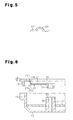
- the sealing member 14 is attached to the lower end of the cylinder head cover 13. Specifically, as shown in Fig. 6 , the protrusion 16 on the main seal 15 of the sealing member 14 is fitted to the groove 19 of the cylinder head cover 13 such that the main seal 15 is attached to the outer periphery of the cylinder head cover 13.
- the first sub seal 21 and the second sub seal 35 which are positioned at the inside of the main seal 15, are positioned so as to correspond to the lower ends of the bosses 28, 42 on the cylinder head cover 13, respectively.
- the main seal 15 is attached to the lower end of the cylinder head cover 13, and each of the sub seals 21, 35 is attached to the lower end of the corresponding one of the bosses 28, 42.
- the cylinder head cover 13 is fixed to the cylinder head 11 by the bolts.
- the bolt is screwed into the screw hole (not shown) on the cylinder head from the screw insertion hole of the cylinder head cover 13 via each insertion hole 18 of the main seal 15 of the sealing member 14. Accordingly, the cylinder head cover 13 is assembled to the cylinder head 11, and the main seal 15 of the sealing member 14 is positioned between the cylinder head 11 and the cylinder head cover 13.
- the bolts 33, 47 are screwed from the cylinder head cover 13 into the screw holes 32, 46 in the cam cap 12 via the bolt insertion cylinders 29, 43 and the sub seals 21, 35. This improves the rigidity of the adjacent portions of the oil pressure feeding port 27 and the sensor attaching holes 41, and the positions of the oil pressure feeding port 27 and the sensor attaching holes 41 are determined.
- the first sub seal 21 and the second sub seal 35 are positioned between the bosses 28, 42 of the cylinder head cover 13 and the cam cap 12, respectively.
- the main seal 15 and the sub seals 21, 35 are integrally formed with each other through the first and second connecting elements 20, 34. Therefore, separate seals are not necessary to be prepared. This simplifies the structure of the sealing structure and reduces the number of parts.
- a sealing structure according to a second embodiment of the present invention will be explained with focusing on the differences from the first embodiment.
- positioning pins 31, 45 are formed next to the bosses 28, 42 on the lower surface of the partition plate 48 so as to protrude downwardly.
- Positioning holes 25, 39 are formed at the middle portions in the longitudinal direction of the first and second connecting elements 20, 34.
- the positioning pins 31, 45 are inserted to the positioning holes 25, 39, respectively.
- the positioning pins 31, 45 do not need to be formed on the lower surface of the partition plate 48, but may be formed on the lower surface of the cylinder head cover 13. In this case, a through holes are formed in the partition plate 48 and the positioning pins 31, 45 pass through the through holes and extend to the first connecting element 20 and the second connecting element 34.
- the second embodiment differs from the first embodiment in that the upper and lower thick portions 26c, 26d, 40c, 40d are formed at the inner corners of the upper and lower bent portions 23a, 23b, 37a, 37b.
- the upper thick portions 26c, 40c protrude downwardly and the lower thick portions 26d, 40d protrude upwardly.
- the positioning pins 31, 45 are inserted to the positioning holes 25, 39 on the first connecting element 20 and the second connecting element 34, respectively. Accordingly, the first and second connecting elements 20, 34 are positioned and maintained in predetermined positions.
- first and second connecting elements 20, 34 are maintained in predetermined positions by the positioning pins 31, 45, vibration of the first and second connecting elements 20, 34 is reliably prevented.
- the positioning pins 31, 45 have efficient function with a simple shape. That is, the positioning pins do not need to be formed in a mushroom shape having a wide distal end, and a complicated molding structure is not necessary.
- the thick portions 26c, 26d, 40c, 40d are formed at the inner corners of the upper and lower bent portions 23a, 23b, 37a, 37b, respectively, the thick portions 26c, 26d, 40c, 40d are prevented from protruding from the upper surface and the lower surface of the first and second connecting elements 20, 34, respectively. Therefore, a total height of each of the first and second connecting elements 20, 34 is reduced.
- the first and second embodiments may be modified as follows.
- Only the ribs 24, 38 may be provided as rigidity improving means for the first and second connecting elements 20, 34.
- only the thick portions 26a, 26b, 26c, 26d, 40a, 40b, 40c, 40d may be provided as rigidity improving means for the first and second connecting elements 20, 34.
- Reinforcing material such as grass fiber may be embedded in the connecting elements 20, 34 as rigidity improving means for the first and second connecting elements 20, 34.
- the present invention is not limited to sealing members between the cylinder head 11 and the cylinder head cover 13 in an engine for a vehicle, but may be embodied as sealing members between other parts.
- the present invention may be embodied as a sealing member provided between a cylinder block and an oil pan.
Landscapes
- Engineering & Computer Science (AREA)
- General Engineering & Computer Science (AREA)
- Mechanical Engineering (AREA)
- Cylinder Crankcases Of Internal Combustion Engines (AREA)
- Seal Device For Vehicle (AREA)
- Gasket Seals (AREA)
Applications Claiming Priority (1)
| Application Number | Priority Date | Filing Date | Title |
|---|---|---|---|
| JP2007272454A JP2009097483A (ja) | 2007-10-19 | 2007-10-19 | シール材及びシール構造 |
Publications (2)
| Publication Number | Publication Date |
|---|---|
| EP2050947A2 true EP2050947A2 (de) | 2009-04-22 |
| EP2050947A3 EP2050947A3 (de) | 2010-04-21 |
Family
ID=40383695
Family Applications (1)
| Application Number | Title | Priority Date | Filing Date |
|---|---|---|---|
| EP08018007A Withdrawn EP2050947A3 (de) | 2007-10-19 | 2008-10-14 | Dichtungselement und Dichtungsstruktur |
Country Status (3)
| Country | Link |
|---|---|
| US (1) | US7934480B2 (de) |
| EP (1) | EP2050947A3 (de) |
| JP (1) | JP2009097483A (de) |
Families Citing this family (6)
| Publication number | Priority date | Publication date | Assignee | Title |
|---|---|---|---|---|
| JP2009243401A (ja) * | 2008-03-31 | 2009-10-22 | Honda Motor Co Ltd | 4サイクルエンジンにおけるシリンダヘッド構造 |
| US8794203B2 (en) * | 2008-11-05 | 2014-08-05 | Ford Global Technologies, Llc | Valve cover with decoupled NVH isolation and sealing features |
| US8833336B2 (en) * | 2009-11-03 | 2014-09-16 | Gregory R. Ernst | Engine dust and dirt shield or cover |
| US9664284B2 (en) * | 2015-08-05 | 2017-05-30 | General Electric Company | Cover system with gasket system therefor |
| JP7090308B2 (ja) * | 2017-09-07 | 2022-06-24 | 内山工業株式会社 | ガスケット |
| CN114215949B (zh) * | 2021-11-11 | 2024-05-28 | 中船双瑞(洛阳)特种装备股份有限公司 | 一种用于高温高压工况防止阀门外漏的自密封装置 |
Citations (4)
| Publication number | Priority date | Publication date | Assignee | Title |
|---|---|---|---|---|
| US3936059A (en) * | 1973-10-03 | 1976-02-03 | Federal-Mogul Corporation | Sealing boundary gasket for compression between flanged portions of two mating metal members |
| JPH10246152A (ja) * | 1997-03-03 | 1998-09-14 | Toyota Motor Corp | シリンダヘッドカバー用ガスケット |
| JP2002195096A (ja) | 2000-12-26 | 2002-07-10 | Toyoda Spinning & Weaving Co Ltd | シリンダヘッドカバー |
| JP2002195098A (ja) * | 2000-12-25 | 2002-07-10 | Toyoda Gosei Co Ltd | シリンダヘッドカバー用ガスケット |
Family Cites Families (19)
| Publication number | Priority date | Publication date | Assignee | Title |
|---|---|---|---|---|
| GB1051747A (de) * | 1964-08-28 | |||
| US5003958A (en) * | 1988-12-27 | 1991-04-02 | Nissan Motor Co., Ltd. | Ignition coil mounting structure for engine |
| US5236394A (en) * | 1990-09-10 | 1993-08-17 | Gkn Automotive, Inc. | External convoluted high speed constant velocity joint boot |
| JP2525726Y2 (ja) | 1990-12-13 | 1997-02-12 | 石川ガスケット 株式会社 | ガスケットの仮止め装置 |
| US5121933A (en) * | 1991-02-08 | 1992-06-16 | Mccord Payen Inc. | Gasket with improved sealing capabilities |
| US5540468A (en) * | 1994-09-12 | 1996-07-30 | Fassman; Arnold | Door opening and closing device for handicapped persons |
| JP4205775B2 (ja) * | 1998-03-03 | 2009-01-07 | 日本ガスケット株式会社 | 係止部を備えた金属ガスケット |
| JP3363781B2 (ja) * | 1998-03-18 | 2003-01-08 | 石川ガスケット株式会社 | 複数のシール部を有する金属板ガスケット |
| US6085709A (en) * | 1998-12-10 | 2000-07-11 | Detroit Diesel Corporation | Engine rocker arm cover having reduced noise transmission |
| US6269787B1 (en) * | 1999-12-22 | 2001-08-07 | Dana Corporation | Rocker cover gasket assembly with integral valve stem seals |
| JP3966003B2 (ja) * | 2002-02-05 | 2007-08-29 | 日産自動車株式会社 | 内燃機関 |
| DE10306211A1 (de) * | 2003-02-13 | 2004-08-26 | Mann + Hummel Gmbh | Dichtung zur Abdichtung einer Verbindung zweier Formteile |
| JP2005090722A (ja) * | 2003-09-19 | 2005-04-07 | Uchiyama Mfg Corp | 多機能ガスケット |
| US20050269788A1 (en) * | 2004-06-02 | 2005-12-08 | Grunfeld Aron A | Gasket assembly and method |
| JP4434012B2 (ja) * | 2004-12-28 | 2010-03-17 | 豊田合成株式会社 | エンジンカバーの取付構造 |
| WO2007007612A1 (ja) | 2005-07-07 | 2007-01-18 | Nok Corporation | ガスケット |
| JP4321504B2 (ja) * | 2005-07-25 | 2009-08-26 | 日産自動車株式会社 | 内燃機関のカム角センサ取付構造 |
| JP4714699B2 (ja) * | 2007-01-16 | 2011-06-29 | 内山工業株式会社 | ガスケット |
| US20090107731A1 (en) * | 2007-10-30 | 2009-04-30 | George Fedorovich | Drillbit seal |
-
2007
- 2007-10-19 JP JP2007272454A patent/JP2009097483A/ja active Pending
-
2008
- 2008-10-07 US US12/246,764 patent/US7934480B2/en not_active Expired - Fee Related
- 2008-10-14 EP EP08018007A patent/EP2050947A3/de not_active Withdrawn
Patent Citations (4)
| Publication number | Priority date | Publication date | Assignee | Title |
|---|---|---|---|---|
| US3936059A (en) * | 1973-10-03 | 1976-02-03 | Federal-Mogul Corporation | Sealing boundary gasket for compression between flanged portions of two mating metal members |
| JPH10246152A (ja) * | 1997-03-03 | 1998-09-14 | Toyota Motor Corp | シリンダヘッドカバー用ガスケット |
| JP2002195098A (ja) * | 2000-12-25 | 2002-07-10 | Toyoda Gosei Co Ltd | シリンダヘッドカバー用ガスケット |
| JP2002195096A (ja) | 2000-12-26 | 2002-07-10 | Toyoda Spinning & Weaving Co Ltd | シリンダヘッドカバー |
Also Published As
| Publication number | Publication date |
|---|---|
| US7934480B2 (en) | 2011-05-03 |
| JP2009097483A (ja) | 2009-05-07 |
| EP2050947A3 (de) | 2010-04-21 |
| US20090102137A1 (en) | 2009-04-23 |
Similar Documents
| Publication | Publication Date | Title |
|---|---|---|
| EP2050947A2 (de) | Dichtungselement und Dichtungsstruktur | |
| US8474418B2 (en) | Partition member for cooling passage of internal combustion engine, cooling structure of internal combustion engine, and method for forming the cooling structure | |
| US8794606B2 (en) | Liquid sealed vibration isolating device | |
| US8490954B2 (en) | Liquid sealed vibration isolating device | |
| JP5440775B2 (ja) | 燃料電池用構成部品およびその製造方法 | |
| US20100264570A1 (en) | Anti-Vibration Device | |
| EP1610042A1 (de) | Elastomerbeschichtete Flachdichtung | |
| JP2009215919A (ja) | ロッカアームユニット及びロッカアームユニットの組立方法 | |
| JP2006161594A (ja) | バルブ装置 | |
| US10767519B2 (en) | Valve stem seal and hermetic sealing structure | |
| US6874460B2 (en) | Integrated oil pan and windage tray | |
| KR100824335B1 (ko) | 실린더 헤드 가스킷 | |
| JP4425907B2 (ja) | 空気路を備えた圧力式アクチュエータ用ダイアフラムケース | |
| CN101080554B (zh) | 具有法兰压力分布补偿装置的法兰盖组件 | |
| EP2236776B1 (de) | Joint de tige de soupape | |
| JP5158950B2 (ja) | ガスケット | |
| CN114482750B (zh) | 开闭体用液封减震器 | |
| JP5063393B2 (ja) | オイルレベルゲージの案内管の取付構造 | |
| KR101868576B1 (ko) | 엔진의 가스켓 조립체 | |
| EP4667792A1 (de) | Gleitschuhstruktur und umkehrventil | |
| JP2024103085A (ja) | バルブの取付構造 | |
| CN222596202U (zh) | 一种点火线圈、发动机及车辆 | |
| CN114592763B (zh) | 开闭体用液封减震器 | |
| CN114555918B (zh) | 液体槽和机动车 | |
| JP2011185288A (ja) | 防振装置 |
Legal Events
| Date | Code | Title | Description |
|---|---|---|---|
| PUAI | Public reference made under article 153(3) epc to a published international application that has entered the european phase |
Free format text: ORIGINAL CODE: 0009012 |
|
| 17P | Request for examination filed |
Effective date: 20081014 |
|
| AK | Designated contracting states |
Kind code of ref document: A2 Designated state(s): AT BE BG CH CY CZ DE DK EE ES FI FR GB GR HR HU IE IS IT LI LT LU LV MC MT NL NO PL PT RO SE SI SK TR |
|
| AX | Request for extension of the european patent |
Extension state: AL BA MK RS |
|
| RIN1 | Information on inventor provided before grant (corrected) |
Inventor name: KOJIMA, HIROTSUGU Inventor name: KATAYAMA, NORIHIRO |
|
| RAP1 | Party data changed (applicant data changed or rights of an application transferred) |
Owner name: TOYOTA BOSHOKU KABUSHIKI KAISHA |
|
| RAP1 | Party data changed (applicant data changed or rights of an application transferred) |
Owner name: TOYOTA BOSHOKU KABUSHIKI KAISHA |
|
| PUAL | Search report despatched |
Free format text: ORIGINAL CODE: 0009013 |
|
| AK | Designated contracting states |
Kind code of ref document: A3 Designated state(s): AT BE BG CH CY CZ DE DK EE ES FI FR GB GR HR HU IE IS IT LI LT LU LV MC MT NL NO PL PT RO SE SI SK TR |
|
| AX | Request for extension of the european patent |
Extension state: AL BA MK RS |
|
| 17Q | First examination report despatched |
Effective date: 20100607 |
|
| AKX | Designation fees paid |
Designated state(s): DE FR |
|
| STAA | Information on the status of an ep patent application or granted ep patent |
Free format text: STATUS: THE APPLICATION IS DEEMED TO BE WITHDRAWN |
|
| 18D | Application deemed to be withdrawn |
Effective date: 20160105 |