EP2050973A2 - Elément de fixation - Google Patents
Elément de fixation Download PDFInfo
- Publication number
- EP2050973A2 EP2050973A2 EP08018156A EP08018156A EP2050973A2 EP 2050973 A2 EP2050973 A2 EP 2050973A2 EP 08018156 A EP08018156 A EP 08018156A EP 08018156 A EP08018156 A EP 08018156A EP 2050973 A2 EP2050973 A2 EP 2050973A2
- Authority
- EP
- European Patent Office
- Prior art keywords
- fastening element
- fastening
- element according
- legs
- components
- Prior art date
- Legal status (The legal status is an assumption and is not a legal conclusion. Google has not performed a legal analysis and makes no representation as to the accuracy of the status listed.)
- Withdrawn
Links
Images


Classifications
-
- F—MECHANICAL ENGINEERING; LIGHTING; HEATING; WEAPONS; BLASTING
- F16—ENGINEERING ELEMENTS AND UNITS; GENERAL MEASURES FOR PRODUCING AND MAINTAINING EFFECTIVE FUNCTIONING OF MACHINES OR INSTALLATIONS; THERMAL INSULATION IN GENERAL
- F16B—DEVICES FOR FASTENING OR SECURING CONSTRUCTIONAL ELEMENTS OR MACHINE PARTS TOGETHER, e.g. NAILS, BOLTS, CIRCLIPS, CLAMPS, CLIPS OR WEDGES; JOINTS OR JOINTING
- F16B5/00—Joining sheets or plates, e.g. panels, to one another or to strips or bars parallel to them
- F16B5/06—Joining sheets or plates, e.g. panels, to one another or to strips or bars parallel to them by means of clamps or clips
- F16B5/0607—Joining sheets or plates, e.g. panels, to one another or to strips or bars parallel to them by means of clamps or clips joining sheets or plates to each other
- F16B5/0621—Joining sheets or plates, e.g. panels, to one another or to strips or bars parallel to them by means of clamps or clips joining sheets or plates to each other in parallel relationship
-
- F—MECHANICAL ENGINEERING; LIGHTING; HEATING; WEAPONS; BLASTING
- F16—ENGINEERING ELEMENTS AND UNITS; GENERAL MEASURES FOR PRODUCING AND MAINTAINING EFFECTIVE FUNCTIONING OF MACHINES OR INSTALLATIONS; THERMAL INSULATION IN GENERAL
- F16B—DEVICES FOR FASTENING OR SECURING CONSTRUCTIONAL ELEMENTS OR MACHINE PARTS TOGETHER, e.g. NAILS, BOLTS, CIRCLIPS, CLAMPS, CLIPS OR WEDGES; JOINTS OR JOINTING
- F16B5/00—Joining sheets or plates, e.g. panels, to one another or to strips or bars parallel to them
- F16B5/02—Joining sheets or plates, e.g. panels, to one another or to strips or bars parallel to them by means of fastening members using screw-thread
- F16B5/0241—Joining sheets or plates, e.g. panels, to one another or to strips or bars parallel to them by means of fastening members using screw-thread with the possibility for the connection to absorb deformation, e.g. thermal or vibrational
-
- Y—GENERAL TAGGING OF NEW TECHNOLOGICAL DEVELOPMENTS; GENERAL TAGGING OF CROSS-SECTIONAL TECHNOLOGIES SPANNING OVER SEVERAL SECTIONS OF THE IPC; TECHNICAL SUBJECTS COVERED BY FORMER USPC CROSS-REFERENCE ART COLLECTIONS [XRACs] AND DIGESTS
- Y10—TECHNICAL SUBJECTS COVERED BY FORMER USPC
- Y10T—TECHNICAL SUBJECTS COVERED BY FORMER US CLASSIFICATION
- Y10T403/00—Joints and connections
- Y10T403/45—Flexibly connected rigid members
- Y10T403/455—Elastomer interposed between radially spaced members
- Y10T403/456—Elastomer encompasses shoulder on inner member
Definitions
- the invention relates to fastening element for connecting two components.
- the invention relates to a fastening element, by means of which two components can be connected to one another such that a predetermined relative movement between the components is possible.
- a fastening element by means of which two components can be connected to one another such that a predetermined relative movement between the components is possible.
- An example of this is the connection of two components which are concentric to one another and which can execute a slight relative movement in the radial and axial directions relative to each other, for example to compensate for thermal expansions.
- the invention has for its object to provide a fastener of the type mentioned, which with a simple structure and simple, cost manufacturability avoids the disadvantages of the prior art and ensures a precise storage of the components together.
- a fastening element which is integrally formed and comprises two parallel, preferably plate-shaped or strip-shaped legs, which are operationally connected via an elastic member which is integrally connected with the legs.
- the two legs are used for attachment to the two components to be connected, wherein each of the components is to be connected to one of the legs.
- the construction is selected such that one of the legs projects substantially at right angles from a first fastening part, which can be connected to a component.
- the other leg is preferably formed extended and has on its side a second fastening part, which can be connected to the other component.
- the fastening element according to the invention thus allows a precise concentric and axial positioning of two components while ensuring a limited, predetermined relative mobility in several directions of movement.
- the fastening element according to the invention is designed so that it in the loading direction, in which a relative movement preferably occurs, having a minimum moment of inertia. Furthermore, it is provided that the stiffness of the fastening element in the loading direction, in which no relative movement or only a minimum relative movement is allowed, is greatest.
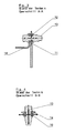
- the prior art shows typical fasteners for connecting two mutually concentric components 1, 2 (see. Fig. 6 ).
- a bearing plate 10 is provided, which is provided with a recess 11 in which a guide ring 12 is arranged with a U-shaped cross-section.
- the guide ring 12 passes through a bearing pin 13, which supports a second bearing plate 14. From the representations of 3 and 4 shows that a three-dimensional mobility between the first bearing plate 10 and the second bearing plate 14 is possible. Furthermore, it follows from the representations that a total of a complicated and complex overall structure is present.
- the Fig. 7 and 8th show an embodiment of the fastener according to the invention.
- This comprises a first leg 3 and a second leg 4 which is parallel to and spaced therefrom and which in each case (see in particular FIG Fig. 9 ) are connected at its free end with an elastic part 5.
- the elastic part 5, which is integrally connected to the two legs 3, 4, has a circular cross-section and is thus partially cylindrical (see. Fig. 7 and 8th ).
- a first fastening part 6 which is provided with a recess and on a component, for example, the component 2 (see. Fig. 13 ) is fixable by means of a screw connection.
- the first leg 3 is extended laterally and comprises a second fastening part 7, which is likewise provided with a fastening recess in order to be attached to the component 1 (FIG. Fig. 13 ) to be screwed.
- the Fig. 9 and 11 each show the directions of movement in three dimensions.
- the Fig. 12 shows a side view, which results in the part-circular cross-section of the elastic member 5, the together with the in Fig. 10 shown cross section leads to the mentioned elastic properties.
- the fastening element according to the invention is thus characterized by a simple structure and a simple construction, which can be exactly predetermined by suitable dimensioning and material selection.
- the wear is minimal compared to the prior art, resulting in a much longer life. Due to the lower assembly costs and the small number of parts results in a significant cost savings. In addition, there is an advantage in terms of weight reduction.
Landscapes
- Engineering & Computer Science (AREA)
- General Engineering & Computer Science (AREA)
- Mechanical Engineering (AREA)
- Insertion Pins And Rivets (AREA)
- Connection Of Plates (AREA)
- Mutual Connection Of Rods And Tubes (AREA)
Applications Claiming Priority (1)
| Application Number | Priority Date | Filing Date | Title |
|---|---|---|---|
| DE102007050159A DE102007050159A1 (de) | 2007-10-19 | 2007-10-19 | Befestigungselement |
Publications (2)
| Publication Number | Publication Date |
|---|---|
| EP2050973A2 true EP2050973A2 (fr) | 2009-04-22 |
| EP2050973A3 EP2050973A3 (fr) | 2010-06-30 |
Family
ID=40184930
Family Applications (1)
| Application Number | Title | Priority Date | Filing Date |
|---|---|---|---|
| EP08018156A Withdrawn EP2050973A3 (fr) | 2007-10-19 | 2008-10-16 | Elément de fixation |
Country Status (3)
| Country | Link |
|---|---|
| US (1) | US20090103975A1 (fr) |
| EP (1) | EP2050973A3 (fr) |
| DE (1) | DE102007050159A1 (fr) |
Families Citing this family (2)
| Publication number | Priority date | Publication date | Assignee | Title |
|---|---|---|---|---|
| DE102011103158B4 (de) | 2011-06-01 | 2015-06-03 | Rolls-Royce Deutschland Ltd & Co Kg | Fluggasturbine mit einer Lagerung eines thermischen Enteisungs-Rohrelements |
| DE102011106964A1 (de) | 2011-07-08 | 2013-01-10 | Rolls-Royce Deutschland Ltd & Co Kg | Fluggasturbinentriebwerk mit Lagerung eines Blütenmischers |
Family Cites Families (13)
| Publication number | Priority date | Publication date | Assignee | Title |
|---|---|---|---|---|
| US1366321A (en) * | 1920-08-03 | 1921-01-18 | Bernard J Kahn | Combined clip and spacer for electric conduits |
| FR2207543A5 (fr) * | 1972-11-20 | 1974-06-14 | Setm Equipements | |
| US4482124A (en) * | 1977-10-07 | 1984-11-13 | General Electric Company | Torsional vibration isolating motor mounting arrangement and method of making the same |
| US4572472A (en) * | 1982-06-02 | 1986-02-25 | Westinghouse Electric Corp. | Electric motor flexible mounting system and method of assembly |
| US4597555A (en) * | 1983-09-02 | 1986-07-01 | Franklin Electric Co., Inc. | Electric motor mount |
| US4991801A (en) * | 1990-03-01 | 1991-02-12 | Trumbull Terry N | Universal support strap |
| GB2268993B (en) * | 1992-07-22 | 1995-02-15 | Nissan Europ Tech Centre | Vehicle body jointing bracket |
| DK173276B1 (da) * | 1998-02-05 | 2000-06-05 | Kongskilde Ind As | Spændestykke, fremgangsmåde til fremstilling af spændestykke, samt landbrugsmaskine, der anvender spændestykket |
| US6761343B2 (en) * | 2001-06-13 | 2004-07-13 | York International Corp. | Single-piece motor mount |
| DE102004041685B3 (de) * | 2004-08-26 | 2006-05-04 | Bayer Materialscience Ag | Verbundbauteil |
| CN101147024B (zh) * | 2005-03-24 | 2010-05-19 | 尼尔·安德鲁·罗伯茨 | 安装或移除构件时使用的临时支撑结构 |
| US20080011909A1 (en) * | 2006-01-09 | 2008-01-17 | Enzo Daddario | Drinking straw holder |
| DE102006008382A1 (de) * | 2006-02-21 | 2007-08-30 | Ford Global Technologies, LLC, Dearborn | Federelement |
-
2007
- 2007-10-19 DE DE102007050159A patent/DE102007050159A1/de not_active Withdrawn
-
2008
- 2008-10-16 EP EP08018156A patent/EP2050973A3/fr not_active Withdrawn
- 2008-10-20 US US12/289,043 patent/US20090103975A1/en not_active Abandoned
Also Published As
| Publication number | Publication date |
|---|---|
| DE102007050159A1 (de) | 2009-04-23 |
| EP2050973A3 (fr) | 2010-06-30 |
| US20090103975A1 (en) | 2009-04-23 |
Similar Documents
| Publication | Publication Date | Title |
|---|---|---|
| EP2184029B1 (fr) | Vis d'extension orthodontique | |
| EP2713818B1 (fr) | Dispositif d'encliquetage pour meuble | |
| DE102008009608A1 (de) | Einrichtung mit einem Flächenelement und einer Klemmeinrichtung | |
| EP3622153B1 (fr) | Commande de meuble à moteur | |
| DE112018007572T5 (de) | Befestigungsstruktur und Energieumwandlungsvorrichtung, welches die Befestigungsstruktur verwendet | |
| DE102012101614A1 (de) | Vorrichtung zum Verschließen eines Gehäuses eines Steckverbinders | |
| DE102013216881A1 (de) | Linearantrieb | |
| DE102010003789A1 (de) | Elastisches Lager mit in seiner Hauptebene beidseitig eingeschnittener Grundplatte | |
| EP2050973A2 (fr) | Elément de fixation | |
| EP1662155B1 (fr) | Fixation de pièce plastique pour véhicule | |
| EP3819645A1 (fr) | Élément de renfort permettant de renforcer un système de contacteur d'essai, utilisation et procédé de montage d'un système de contacteur d'essai | |
| DE102018118983B3 (de) | Verbindungsanordnung für eine Scharnieranordnung sowie Scharnieranordnung zur Verstellung eines Heckspoilers | |
| EP2407062B1 (fr) | Dispositif de retenue | |
| EP2323871B1 (fr) | Système d'airbag | |
| DE19740799B4 (de) | Dämpfungselement | |
| DE102012017979B4 (de) | Spindelantrieb | |
| EP4216382A1 (fr) | Agencement doté d'un rail de support et de boîtiers juxtaposés sur ce rail | |
| DE202010004534U1 (de) | Befestigungseinrichtung mit Spannschraube | |
| DE10320737A1 (de) | Schwingungsdämpfungsvorrichtung und Federelement dafür | |
| DE102006029164B3 (de) | Kotflügelanordnung zur Abdeckung eines Fahrzeugrades | |
| DE102015225283A1 (de) | Differentiallageranordnung | |
| DE102005044127B4 (de) | Trägerteil für einen Sammelschienenträger sowie Sammelschienenträger | |
| DE102012107857A1 (de) | Lagerbuchse, insbesondere für einen Fahrzeugsitz | |
| DE102006017224A1 (de) | Vorrichtung zur Befestigung eines Stabilisators an einem Kraftfahrzeugaufbau | |
| DE102018204195A1 (de) | Spindelantrieb und Komfortantrieb mit einem Spindelantrieb |
Legal Events
| Date | Code | Title | Description |
|---|---|---|---|
| PUAI | Public reference made under article 153(3) epc to a published international application that has entered the european phase |
Free format text: ORIGINAL CODE: 0009012 |
|
| AK | Designated contracting states |
Kind code of ref document: A2 Designated state(s): AT BE BG CH CY CZ DE DK EE ES FI FR GB GR HR HU IE IS IT LI LT LU LV MC MT NL NO PL PT RO SE SI SK TR |
|
| AX | Request for extension of the european patent |
Extension state: AL BA MK RS |
|
| PUAL | Search report despatched |
Free format text: ORIGINAL CODE: 0009013 |
|
| AK | Designated contracting states |
Kind code of ref document: A3 Designated state(s): AT BE BG CH CY CZ DE DK EE ES FI FR GB GR HR HU IE IS IT LI LT LU LV MC MT NL NO PL PT RO SE SI SK TR |
|
| AX | Request for extension of the european patent |
Extension state: AL BA MK RS |
|
| RIC1 | Information provided on ipc code assigned before grant |
Ipc: E04B 1/26 20060101ALI20100527BHEP Ipc: F16B 5/06 20060101AFI20090109BHEP |
|
| AKY | No designation fees paid | ||
| STAA | Information on the status of an ep patent application or granted ep patent |
Free format text: STATUS: THE APPLICATION IS DEEMED TO BE WITHDRAWN |
|
| 18D | Application deemed to be withdrawn |
Effective date: 20110104 |