EP2051498A2 - Appareil de traitement d'informations, appareil de traitement d'images et procédé associé - Google Patents
Appareil de traitement d'informations, appareil de traitement d'images et procédé associé Download PDFInfo
- Publication number
- EP2051498A2 EP2051498A2 EP08166581A EP08166581A EP2051498A2 EP 2051498 A2 EP2051498 A2 EP 2051498A2 EP 08166581 A EP08166581 A EP 08166581A EP 08166581 A EP08166581 A EP 08166581A EP 2051498 A2 EP2051498 A2 EP 2051498A2
- Authority
- EP
- European Patent Office
- Prior art keywords
- dot
- threshold matrix
- lattice points
- halftone
- threshold
- Prior art date
- Legal status (The legal status is an assumption and is not a legal conclusion. Google has not performed a legal analysis and makes no representation as to the accuracy of the status listed.)
- Granted
Links
- 238000012545 processing Methods 0.000 title claims abstract description 27
- 238000000034 method Methods 0.000 title claims description 57
- 230000010365 information processing Effects 0.000 title claims description 11
- 238000006073 displacement reaction Methods 0.000 claims abstract description 46
- 239000011159 matrix material Substances 0.000 claims abstract description 42
- 239000013598 vector Substances 0.000 claims description 36
- 230000015654 memory Effects 0.000 claims description 12
- 238000000638 solvent extraction Methods 0.000 claims description 6
- 238000005192 partition Methods 0.000 claims description 3
- 238000003672 processing method Methods 0.000 claims description 3
- 230000008569 process Effects 0.000 description 21
- 230000006870 function Effects 0.000 description 15
- 238000004891 communication Methods 0.000 description 8
- 238000010586 diagram Methods 0.000 description 6
- 230000000694 effects Effects 0.000 description 5
- 230000003287 optical effect Effects 0.000 description 5
- 230000001788 irregular Effects 0.000 description 4
- 230000008878 coupling Effects 0.000 description 3
- 238000010168 coupling process Methods 0.000 description 3
- 238000005859 coupling reaction Methods 0.000 description 3
- 230000015572 biosynthetic process Effects 0.000 description 2
- 230000006866 deterioration Effects 0.000 description 2
- 238000012546 transfer Methods 0.000 description 2
- 229910021417 amorphous silicon Inorganic materials 0.000 description 1
- 238000013459 approach Methods 0.000 description 1
- 230000008901 benefit Effects 0.000 description 1
- 235000019646 color tone Nutrition 0.000 description 1
- 230000007423 decrease Effects 0.000 description 1
- 230000002542 deteriorative effect Effects 0.000 description 1
- 238000011161 development Methods 0.000 description 1
- 238000009792 diffusion process Methods 0.000 description 1
- 238000004090 dissolution Methods 0.000 description 1
- 238000003384 imaging method Methods 0.000 description 1
- 230000000873 masking effect Effects 0.000 description 1
- 238000012986 modification Methods 0.000 description 1
- 230000004048 modification Effects 0.000 description 1
- 230000002093 peripheral effect Effects 0.000 description 1
- 230000002040 relaxant effect Effects 0.000 description 1
- 239000004065 semiconductor Substances 0.000 description 1
- 229910052709 silver Inorganic materials 0.000 description 1
- 239000004332 silver Substances 0.000 description 1
- -1 silver halide Chemical class 0.000 description 1
- 230000000087 stabilizing effect Effects 0.000 description 1
- 239000002344 surface layer Substances 0.000 description 1
- 230000002194 synthesizing effect Effects 0.000 description 1
Images






Classifications
-
- H—ELECTRICITY
- H04—ELECTRIC COMMUNICATION TECHNIQUE
- H04N—PICTORIAL COMMUNICATION, e.g. TELEVISION
- H04N1/00—Scanning, transmission or reproduction of documents or the like, e.g. facsimile transmission; Details thereof
- H04N1/40—Picture signal circuits
- H04N1/405—Halftoning, i.e. converting the picture signal of a continuous-tone original into a corresponding signal showing only two levels
Definitions
- the present invention relates to an information processing apparatus, image processing apparatus and method thereof, which create and use a halftone screen.
- An electrophotographic printing apparatus which has an exposure process for removing charges from a uniformly charged surface layer of a photosensitive drum, which is made up of an organic photoconductor (OPC), amorphous silicon, or the like, by scanning a light beam, has a non-linear characteristic. Also, complexity of an electrophotography process including development, transfer, fixing, and the like also causes the non-linear characteristic.
- OPC organic photoconductor
- a print image by an electrophotographic printing apparatus is largely influenced by variations of a spatial frequency due to the non-linear characteristic of the electrophotography process.
- a halftone dot method is used in consideration of the non-linear characteristic.
- a fundamental spatial frequency is fixed, and dots can be stably recorded without being influenced by variations of the spatial frequency.
- the screen ruling of halftone dots is N lines/inch
- a print image can be stably formed.
- the fundamental frequency of a halftone dot screen of 200 lines/inch is 4 cycles/mm. That is, by stabilizing the electrophotography process at the spatial frequency of 4 cycles/mm, the image reproduction characteristic of the printing apparatus can be improved.
- An AM modulation method based on the halftone dot method can obtain a stable image reproduction characteristic.
- moiré is readily generated since C, M, Y, and K color tones are superposed in color printing.
- screen angles are changed for respective color components to drive moiré beats generated among color components toward the high frequency side, thus visually obscuring moire.
- moiré due to superposition of color toners is suppressed by setting the Y screen angle to be 30°, and the C, M, and K screen angles to be 0° or 60°.
- the FM modulation method is popularly adopted in an ink-jet system, thermal transfer system, and the like, since it generates a random layout of print dots, has high tonality, and is free from any moire due to superposition of color components.
- the dot interval changes, and cannot be freely controlled. For example, as the density value becomes higher, the dot interval is gradually reduced. For this reason, the spatial frequency characteristic changes to the high frequency side, and is directly influenced by the frequency characteristic of a printing apparatus. Therefore, the FM modulation method is not suited to an electrophotographic printing apparatus, which is readily influenced by spatial frequency variations.
- a hybrid halftone method attracts attention.
- This method is an intermediate method of the AM and FM modulation methods, and has features of both the methods.
- the hybrid halftone method clusters dots to vary dot intervals. Since the dot interval variations are irregular and anisotropic, the spatial correlation among dots lowers, thus suppressing generation of moiré.
- the hybrid halftone method deprives periodicity by clustering dots and moving lattice points (the central positions of halftone dots) using a random number and rotation manipulation, thereby suppressing generation of moiré.
- Various methods of generating a hybrid halftone screen have been proposed. These methods have an advantage (print stability) of the AM modulation method and those (moiré dissolution, high resolution) of the FM modulation method, and an image output with high screen ruling and high image quality is expected.
- the hybrid halftone method targets a printer of a high resolution (e.g., 2400 dpi), and is premised on formation of one halftone dot at a high resolution.
- a printer of a high resolution e.g., 2400 dpi
- an office-use electrophotographic printer has a resolution as low as 600 dpi, and it is difficult to achieve both high halftone-dot screen ruling and a sufficient tone characteristic.
- heterogeneity in pitch of an engine that scans a light beam, banding noise due to mechanical vibrations, and the like cause considerable deterioration of image quality.
- special attention is needed.
- black and white dots are laid out in a checkerboard pattern to blacken white dots from outside (to grow black dots) to have an intermediate density as a boundary. That is, black and white dots grow to be symmetrical about a density axis, so as to stabilize white dots.
- the screen ruling of halftone dots is reduced to about ⁇ (1/2) ⁇ 0.7 compared to a case without introducing any white dots (all black dots).
- a printer of 600 dpi When a printer of 600 dpi is used to form a halftone dot screen of 175 lines on average, about 12 pixels are used for a halftone dot that forms one threshold matrix using the threshold matrix of 3.4 ⁇ 3.4 pixels on average in a state without introducing any white dots.
- a threshold matrix is defined by about 2.4 ⁇ 2.4 pixels, and only about six pixels are used for a halftone dot that forms one threshold matrix. That is, it becomes difficult to form a desired halftone dot screen, that is, it is difficult to introduce white dots to an office-use printer with a low resolution. In other words, stable tone reproduction with high screen running and high image quality is demanded for a low-resolution printer without introducing any white dots.
- an information processing apparatus According to a first aspect of the present invention, there is provided an information processing apparatus according to claim 1.
- an image processing apparatus According to a second aspect of the present invention, there is provided an image processing apparatus according to claim 11.
- a halftone screen which is applicable to a low-resolution electrophotographic printer can be created. Also, a halftone screen which can suppress generation of moiré and can attain satisfactory tone reproduction can be created.
- an image processing apparatus including storing means for storing a threshold matrix; comparing means for inputting image data and the threshold matrix from the storing means in synchronism with synchronizing signals of the image forming apparatus, and for comparing the image data with threshold values in cells of the threshold matrix; and driving means for driving a laser light source of the image forming apparatus in accordance with the comparison result, characterized in that the threshold matrix is generated by the above information processing apparatus.
- an image processing apparatus which includes storing means for storing a threshold matrix; comparing means for inputting image data and the threshold matrix from the storing means in synchronism with synchronizing signals of an image forming apparatus, and for comparing the image data with threshold values in cells of the threshold matrix; and driving means for driving a laser light source of the image forming apparatus in accordance with the comparison result, characterized in that the cells corresponding to blank regions are concentrated in portions of the threshold matrix.
- the present invention is able to produce an image in which generation of moiré is suppressed and which satisfactory tone reproduction can be formed using a low-resolution electrophotographic printer.
- Fig. 1 is a block diagram showing the arrangement of an example image processing apparatus according to an embodiment
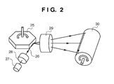
- Fig. 2 is a view showing the arrangement of an optical system of a printer
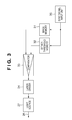
- Fig. 3 is a block diagram showing the arrangement of a dot generator which generates a hybrid halftone screen (HHS);
- HHS hybrid halftone screen
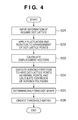
- Fig. 4 is a flowchart for explaining processing for generating an HHS
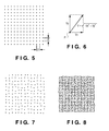
- Fig. 5 is a view showing a square dot lattice
- Fig. 6 is a view showing a "fluctuation" manipulation
- Fig. 7 is a view showing an arrangement of dot-lattice points displaced by the "fluctuation" manipulation
- Fig. 8 is a view showing displacement vectors of respective lattice points by the "fluctuation" manipulation
- Fig. 9 is a view showing an arrangement of dot-lattice points displaced by a "rotation" manipulation to have a given point as the center of rotation;
- Fig. 10 is a view showing displacement vectors of respective lattice points by the "rotation" manipulation
- Fig. 11 is a view showing Voronoi polygons and the centroids of the Voronoi polygons
- Fig. 12 is a view showing one of Voronoi polygons
- Fig. 13 is a view showing a method of determining a halftone-dot shape by flattening a Voronoi polygon along a displacement vector;
- Fig. 14 is a view showing a halftone dot near highlight
- Fig. 15 is a view showing a state in which a halftone dot grows to be in contact with adjacent Voronoi polygons
- Fig. 16 is a view showing a state in which a halftone dot further grows
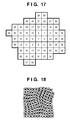
- Fig. 17 is a view showing a threshold matrix used to blacken a certain Voronoi polygon
- Figs. 18 to 20 are views showing blackening processes (growing of halftone dots);
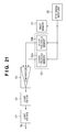
- Fig. 21 is a block diagram showing an example of the arrangement of a dot generator used upon increasing the number of tones of a print image
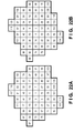
- Figs. 22A and 22B are views showing threshold matrices stored in dither threshold memories
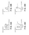
- Figs. 23A to 23D are graphs for explaining emission control of a light source
- Fig. 24 is a flowchart for explaining processing for generating an HHS according to the second embodiment
- Figs. 25A and 25B are views for explaining generation of banding noise
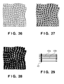
- Fig. 26 is a view showing displacement vectors of respective lattice points displaced in the sub-scan direction
- Fig. 29 is a view for explaining an effect due to coupling of halftone dots in the sub-scan direction.
- Fig. 1 is a block diagram showing the arrangement of an image processing apparatus according to an embodiment.
- Functions of a multi-functional peripheral equipment (MFP) 10, which has a scanner 11 and an electrophotographic printer 12, are controlled by a controller 13 incorporated in the MFP 10.
- the controller 13 corresponds to the information processing apparatus in the embodiment.
- a microcontroller (CPU) 17 of the controller 13 executes an operating system (OS) and various programs stored in a read only memory (ROM) 14 and hard disk drive (HDD) 16 using a random access memory (RAM) 15 as a work memory.
- the HDD 16 stores programs such as a control program, image processing program, and the like, and image data.
- the CPU 17 displays a user interface on a display unit 18 and inputs user's instructions from software keys on the display unit 18 and a keyboard of an operation panel 19. For example, when a user's instruction indicates a copy instruction, the CPU 17 controls the printer 12 to print a document image scanned by the scanner 11 (copy function).
- a communication unit 20 is a communication interface which is connected to a public line and computer network (although not shown).
- the CPU 17 controls the communication unit 20 to send a document image scanned by the scanner 11 to a communication partner designated by the user as a facsimile image (facsimile function).
- the CPU 17 controls the communication unit 20 to send a document image scanned by the scanner 11 to a designated server (push scan function).
- the communication unit 20 receives a facsimile image
- the CPU 17 controls the printer 12 to print the received image (facsimile function).
- the CPU 17 controls the printer 12 to print an image in accordance with the print job (printer function).
- the CPU 17 sends a document image scanned by the scanner 11 to a designated server or client in accordance with the scan job (pull scan function).
- Fig. 2 is a view showing the arrangement of an optical system of the printer 12.
- a light beam 26 emitted by a light source 27 such as a semiconductor laser element or the like enters a reflecting surface of a rotary polygonal mirror 25 via a collimator lens 28 based on a spherical system or anamorphic optical system.
- the light beam 26 deflected by rotation of the rotary polygonal mirror 25 is imaged on a rotating photosensitive drum 30 via an imaging lens 29 such as an f- ⁇ lens or the like, thus optically scanning the surface of the photosensitive drum 30.
- Fig. 3 is a block diagram showing the arrangement of a dot generator which generates a hybrid halftone screen (HHS). Note that the dot generator is configured as a part of the controller 13.
- HHS hybrid halftone screen
- a sync signal input unit 35 inputs, as synchronizing signals, a horizontal synchronizing signal Hsync indicating the scan timing of one line, vertical synchronizing signal Vsync indicating the scan timing of one page, and pixel clocks Vclock from the printer 12. These synchronizing signals are sequentially input to an image memory 31 allocated on the RAM 15, thus outputting image data corresponding to the scan position of the photosensitive drum 30. The synchronizing signals are sequentially input to a dither threshold memory 32 allocated on the ROM 14 or RAM 15, thus outputting a threshold matrix (to be described later) corresponding to the scan position of the photosensitive drum 30.
- a laser driver 34 drives the light source 27 in accordance with the binary signals output from the comparator 33, thereby controlling light emission of the light source 27. That is, when the output signal from the comparator 33 is '1', the laser driver 34 controls the light source 27 to output the light beam 26 (laser ON); when the output signal is '0', it controls the light source 27 not to output the light beam 26 (laser OFF).
- Fig. 4 is a flowchart for explaining processing for creating an HHS.
- the CPU 17 executes this processing.
- the CPU 17 receives information of an aligned (regularly arranged) square dot lattice (lattice interval p) from the ROM 14 or HDD 16 (S21).
- Fig. 5 is a view showing the square dot lattice which is formed by aligning dot-lattice points at an interval p.
- the density of dot-lattice points, which gives an average lattice interval of an HHS is determined so that the screen ruling of an image to be formed is a target value.
- the CPU 17 applies "fluctuation” and “rotation” manipulations to an arrangement of dot-lattice points (S22), and calculates displacement vectors from the application result (S23).
- Fig. 6 is a view showing the "fluctuation” manipulation, which applies random displacements Vx and Vy to a dot-lattice point P in the x- and y-directions.
- Fig. 7 is a view showing the arrangement of dot-lattice points displaced by the "fluctuation" manipulation.
- Fig. 8 is a view showing displacement vectors of respective dot-lattice points by the "fluctuation” manipulation, and there is no correlation between displacement vectors since random displacements are applied.
- Fig. 9 is a view showing the arrangement of dot-lattice points displaced by the "rotation" manipulation to have a point 132 as the center of rotation.
- (Px, Py) are the coordinates of a dot-lattice point before rotation
- (Px', Py') are the coordinates of the dot-lattice point after rotation
- (Jx, Jy) are the coordinates of the center 132 of rotation.
- Fig. 10 is a view showing displacement vectors of respective dot-lattice points after the "rotation" manipulation, and there is no correlation between displacement vectors since random displacements are applied.
- the Voronoi polygon represents an influential zone of the dot-lattice point Pi.
- Each side (Voronoi boundary) of the Voronoi polygon is a line segment that couples the circumcenters of Delaunay triangles.
- the Delaunay triangle has, as sides, line segments that couple adjacent dot-lattice points, and is uniquely determined with respect to the dot-lattice point. Therefore, the Voronoi polygon is also uniquely determined.
- Voronoi polygon including one dot-lattice point is formed, and that Voronoi polygon is used to define a halftone-dot shape.
- the initial square dot lattice has periodicity, but that periodicity is disturbed by the "fluctuation” and “rotation” manipulations. Therefore, generation of moiré can be suppressed.
- the CPU 17 sets the centroids of the Voronoi polygons as the centers of blackening (growing of halftone dots). Note that the centroid of each Voronoi polygon is calculated by partitioning the Voronoi polygon into triangles, calculating the centroids and areas of the triangles, weighting the centroids of the triangles by the areas of the corresponding triangles, and calculating an average value of the centroids.
- Fig. 11 is a view showing Voronoi polygons and the centroids ( ⁇ marks) of these Voronoi polygons.
- the position of centroid is set as a new center of blackening, so that an effect of relaxing over-approaching of (separating off) dot-lattice points is obtained, and this process is effective for homogeneity and uniformity.
- the CPU 17 determines a blackening region (halftone-dot shape) (S25).
- Fig. 12 is a view showing one of Voronoi polygons, and a Voronoi polygon 136 has a centroid 134 and resultant displacement vector 135.
- Fig. 13 is a view showing a method of determining a halftone-dot shape by flattening the Voronoi polygon 136 along the resultant displacement vector 135.
- Vectors 135a are allocated at respective vertices so that the vertices of the Voronoi polygon 136 match the midpoint of the resultant displacement vector 135, and polygons 136a and 136b similar to the Voronoi polygon 136 are generated to have start and end points of the vectors 135a as vertices. That is, the polygons 136a and 136b obtained by expanding the Voronoi polygon 136 along the vectors 135a in respective directions are generated.
- a convex hull polygon (flattened polygon) ABCDEFG indicating the halftone-dot shape is generated from vertices A, B, and C of the polygon 136a and vertices D, E, F, and G of the polygon 136b.
- a polygon as an (N+2)-gon at a maximum can be generated from the Voronoi polygon as an N-gon.
- Fig. 14 is a view showing a halftone dot near highlight when tone values are small.
- the polygon ABCDEFG enlarges to have, as the center, the centroid 134 of the Voronoi polygon along with the growth of a halftone dot while holding a similar shape. That is, the centroid 134 of the Voronoi polygon is defined as the center of growth of the halftone dot.
- Fig. 15 is a view showing a state in which the halftone dot grows (as the tone values increase), and is in contact with adjacent Voronoi polygons.
- sides BC and EF in directions along the displacement vector of the polygon ABCDEFG are brought into contact with the sides of the adjacent Voronoi polygons.
- the sides BC and EF are parallel to the corresponding sides of the Voronoi polygon before flattening, and are brought into contact with the adjacent Voronoi polygons not by points but by sides.
- Fig. 16 is a view showing a state in which the halftone dot further grows.
- the halftone dot grows in a direction perpendicular to the direction of the displacement vector, and sides AB and DE are brought into contact with the sides of the adjacent Voronoi polygons.
- ⁇ P1A'G' and ⁇ P2C'D' remain as blank regions in this state, and blank regions are concentrated to portions in the Voronoi polygon before flattening.
- Figs. 18 to 20 are views showing the blackening processes (growing of halftone dots), that is, a state in which halftone dots grow along the directions of the displacement vectors.
- Fig. 17 is a view showing a threshold matrix used to blacken a certain Voronoi polygon (to grow a halftone dot).
- a threshold matrix is prepared by partitioning the interior of a Voronoi polygon in accordance with the dot size of the printer 12, and setting, in cells, thresholds which are used when a dot of the printer 12 is switched from OFF to ON, and correspond to pixel values.
- a Voronoi polygon includes many pixels (cells)
- the halftone-dot shape during the growth process is nearly similar to the aforementioned flattened polygon.
- the number of pixels (cells) included in one Voronoi polygon is very small, and the halftone-dot shape during the growth process is not similar to the flattened polygon but it is modified slightly.
- the concentration effect of the white dot area remains unchanged.
- the CPU 17 does not create a threshold matrix of a Voronoi polygon corresponding to one dot-lattice point, but creates threshold matrices of Voronoi polygons for the entire HHS.
- These threshold matrices are stored in, for example, the HDD 16 in association with the positions of dot-lattice points before displacement.
- the number of tones can be increased by adding pulse width modulation of the light beam by the laser driver 34.
- Fig. 21 is a block diagram showing the arrangement of a dot generator upon increasing the number of tones of a print image.
- this dot generator includes two dither threshold memories 32a and 32b.
- Figs. 22A and 22B are views showing threshold matrices stored in the dither threshold memories 32a and 32b, and thresholds are alternately set so that Fig. 22A indicates odd thresholds, and Fig. 22B indicates even thresholds. That is, the dither threshold memory 32a stores the threshold matrix shown in Fig. 22A , and the dither threshold memory 32b stores the threshold matrix shown in Fig. 22B in association with a certain Voronoi polygon.
- input data needs to be normalized by 120. That is, if image data is defined by 8 bits, the comparator 33 calculates image data ⁇ 120/255, and executes the above comparison using the normalized image data. In the example shown in Figs. 22A and 22B , the normalized image data needs to have one significant digit after the decimal point.
- a peak value of the light intensity of the pulse width T/2 is lower than that of the light intensity of the pulse width T, and exposure by the pulse width T/2 is very unstable.
- the laser driver 34 controls the emission timing of the light source 27, so that a dot to be formed with the pulse width T/2 (to be referred to as a half dot hereinafter) neighbors that formed or to be formed with the pulse width T (to be referred to as a full dot hereinafter).
- Fig. 23C shows an example in which the emission timing of the light source 27 is controlled to form a half dot on the left side of a dot width and then to form a full dot.
- Fig. 23D shows an example in which the emission timing of the light source 27 is controlled to form a half dot on the right side of a dot width and then to form a full dot. Since the half dot is formed adjacent to the full dot, the half dot can be stably formed.
- the controller 13 of the MFP 10 generates the HHS.
- an HHS with an average lattice interval according to the screen ruling of an image to be formed may be created in advance and may be stored in the HDD 16 or the like. Then, an HHS required for image formation may be loaded onto the dither threshold memory 32.
- a hybrid halftone screen which is also applicable to an electrophotographic office printer can be generated.
- HHS hybrid halftone screen
- the tonality in a high-density region can be stabilized due to clustering of blank regions. Therefore, in the electrophotographic office printer, stable tone reproduction with high screen ruling and high image quality in which moiré is suppressed can be achieved without introducing any white dots.
- Fig. 24 is a flowchart for explaining processing for generating an HHS according to the second embodiment.
- the CPU 17 executes this processing.
- the flowchart shown in Fig. 24 is the same or similar to the process shown in Fig. 4 , except unlike in the processing shown in Fig. 4 , a displacement in the sub-scan direction is applied to the arrangement of dot-lattice points (S27).
- an electrophotographic printing apparatus is readily influenced by heterogeneity in pitch and banding noise.
- a laser spot 40 is scanned on the surface of the photosensitive drum 30 in the main scan direction, and scan lines 41a and 41b have a regular interval in a sub-scan direction 44.
- scan lines 42a and 42b with an irregular interval are formed, as indicated by broken lines in Fig. 25B .
- a band-shaped stripe pattern (so-called banding noise) appears on a print image, thus considerably deteriorating image quality.
- a displacement in the sub-scan direction 44 is applied to the arrangement of dot-lattice points.
- the coupling strength of halftone dots in the sub-scan direction can be controlled.
- Fig. 26 is a view showing displacement vectors of dot-lattice points displaced in the sub-scan direction. Compared to the displacement vectors shown in Fig. 10 , vector components in the sub-scan direction (in the vertical direction in Fig. 26 ) increase.
- Fig. 29 is a view for explaining an effect due to coupling of halftone dots in the sub-scan direction.
- the laser spot 40 has an elliptic shape having the sub-scan direction 44 as a major axis. Even when the scan lines 42a and 42b suffer heterogeneity in pitch, since a line contiguous in the sub-scan direction 44 is formed by overlapping the positions of the laser spot 40, it is hardly influenced by heterogeneity in pitch. On the other hand, a line contiguous in the main scan direction can hardly receive an overlapping effect of the laser spot 40, and banding noise cannot be eliminated.
- vertical lines (those along the sub-scan direction) and horizontal lines (those along the main scan direction), each of which has a one-pixel width, are drawn at equal intervals, that is, every third pixel.
- the vertical lines do not receive any influence of heterogeneity in pitch.
- the horizontal lines receive the influence of heterogeneity in pitch, and the interval between the horizontal lines changes to cause heterogeneity in density, thus generating banding noise.
- the present invention can be applied to a system constituted by a plurality of devices (e.g., host computer, interface, reader, printer) or to an apparatus comprising a single device (e.g., copying machine, facsimile machine).
- devices e.g., host computer, interface, reader, printer
- apparatus comprising a single device (e.g., copying machine, facsimile machine).
- the present invention can provide a storage medium storing program code for performing the above-described processes to a computer system or apparatus (e.g., a personal computer), reading the program code, by a CPU or MPU of the computer system or apparatus, from the storage medium, then executing the program.
- a computer system or apparatus e.g., a personal computer
- reading the program code by a CPU or MPU of the computer system or apparatus, from the storage medium, then executing the program.
- the program code read from the storage medium realizes the functions according to the embodiments.
- the storage medium such as a floppy disk, a hard disk, an optical disk, a magnetooptical disk, CD-ROM, CD-R, a magnetic tape, a nonvolatile type memory card, and ROM can be used for providing the program code.
- the present invention includes a case where an OS (operating system) or the like working on the computer performs a part or entire processes in accordance with designations of the program code and realizes functions according to the above embodiments.
- the present invention also includes a case where, after the program code read from the storage medium is written in a function expansion card which is inserted into the computer or in a memory provided in a function expansion unit which is connected to the computer, CPU or the like contained in the function expansion card or unit performs a part or entire process in accordance with designations of the program code and realizes functions of the above embodiments.
- the storage medium stores program code corresponding to the flowcharts described in the embodiments.
- a halftone screen which is applicable to a low-resolution electrophotographic printer is created.
- dot-lattice points arranged in a predetermined region are displaced using rotation processing, the predetermined region is partitioned into polygons each of which surrounds the dot-lattice point.
- a threshold matrix used to grow a halftone dot, which is surrounded by each polygon, in a direction of the displacement is generated.
Landscapes
- Engineering & Computer Science (AREA)
- Multimedia (AREA)
- Signal Processing (AREA)
- Image Processing (AREA)
- Facsimile Image Signal Circuits (AREA)
- Color, Gradation (AREA)
Applications Claiming Priority (1)
| Application Number | Priority Date | Filing Date | Title |
|---|---|---|---|
| JP2007269529A JP4909232B2 (ja) | 2007-10-16 | 2007-10-16 | 情報処理装置、および画像処理装置、並びに、それらの方法 |
Publications (3)
| Publication Number | Publication Date |
|---|---|
| EP2051498A2 true EP2051498A2 (fr) | 2009-04-22 |
| EP2051498A3 EP2051498A3 (fr) | 2010-01-20 |
| EP2051498B1 EP2051498B1 (fr) | 2013-04-10 |
Family
ID=40293785
Family Applications (1)
| Application Number | Title | Priority Date | Filing Date |
|---|---|---|---|
| EP08166581.2A Not-in-force EP2051498B1 (fr) | 2007-10-16 | 2008-10-14 | Appareil de traitement d'informations, appareil de traitement d'images et procédé associé |
Country Status (4)
| Country | Link |
|---|---|
| US (1) | US8149463B2 (fr) |
| EP (1) | EP2051498B1 (fr) |
| JP (1) | JP4909232B2 (fr) |
| CN (1) | CN101415062B (fr) |
Families Citing this family (18)
| Publication number | Priority date | Publication date | Assignee | Title |
|---|---|---|---|---|
| JP4753191B2 (ja) * | 2008-05-15 | 2011-08-24 | 一夫 相坂 | 画像認識方法 |
| US8520277B2 (en) * | 2010-08-03 | 2013-08-27 | Canon Kabushiki Kaisha | Image processing apparatus, image processing method, and storage medium |
| JP2012248997A (ja) * | 2011-05-26 | 2012-12-13 | Oki Data Corp | スクリーン画像生成方法および画像形成装置 |
| JP5644808B2 (ja) * | 2012-04-27 | 2014-12-24 | コニカミノルタ株式会社 | 画像処理装置及び画像処理方法 |
| JP6099952B2 (ja) | 2012-11-29 | 2017-03-22 | キヤノン株式会社 | ガンマ補正テーブル作成方法、または、ガンマ補正テーブルを用いた画像処理方法及びその制御方法 |
| CN103152509B (zh) * | 2013-04-02 | 2015-04-01 | 武汉大学 | 基于打印机非线性特性的图像半色调阈值矩阵设计方法 |
| EP3051358B1 (fr) * | 2013-09-27 | 2020-07-22 | Canon Kabushiki Kaisha | Élément conducteur électrophotographique, cartouche de traitement, et dispositif électrophotographique |
| JP6192466B2 (ja) * | 2013-09-27 | 2017-09-06 | キヤノン株式会社 | 電子写真用の導電性部材、プロセスカートリッジおよび電子写真装置 |
| CN105579913B (zh) | 2013-09-27 | 2018-02-16 | 佳能株式会社 | 电子照相用导电性构件、处理盒和电子照相设备 |
| GB2522422A (en) * | 2014-01-22 | 2015-07-29 | Landa Corp Ltd | Apparatus and method for half-toning |
| JP6351342B2 (ja) * | 2014-04-04 | 2018-07-04 | キヤノン株式会社 | ドット配置または閾値マトリクスの作成方法、画像処理装置、及び記憶媒体 |
| CN103985320A (zh) * | 2014-05-27 | 2014-08-13 | 利亚德光电股份有限公司 | 抑制摩尔纹的方法以及抑制摩尔纹的显示装置 |
| JP6441046B2 (ja) * | 2014-11-26 | 2018-12-19 | 三菱製紙株式会社 | 光透過性導電材料 |
| CN104537654B (zh) * | 2014-12-19 | 2017-04-12 | 大连理工大学 | 利用半色调点位置失真打印图像篡改取证方法 |
| US10410100B1 (en) | 2017-11-14 | 2019-09-10 | Landa Corporation Ltd. | AM Screening |
| CN111324470B (zh) * | 2020-01-20 | 2023-11-07 | 北京百度网讯科技有限公司 | 用于生成信息的方法及装置 |
| CN111724322B (zh) * | 2020-06-19 | 2023-08-22 | 杭州海康机器人股份有限公司 | 去除激光条纹图像噪点的方法和系统 |
| JP2024147995A (ja) * | 2023-04-04 | 2024-10-17 | キヤノン株式会社 | 画像形成装置 |
Citations (3)
| Publication number | Priority date | Publication date | Assignee | Title |
|---|---|---|---|---|
| US6128099A (en) | 1995-06-08 | 2000-10-03 | Delabastita; Paul A. | Halftone screen generator, halftone screen and method for generating same |
| US20040223189A1 (en) | 2003-05-09 | 2004-11-11 | Anoop Bhattacharjya | Rapid design of smooth multi-level multi-frequency screens |
| EP1646222A2 (fr) | 2004-10-08 | 2006-04-12 | Dainippon Screen Mfg., Co., Ltd. | Procédé pour générer une matrice de seuil pour la génération d'une image à demi-teintes et support d'enregistrement stockant les données d'une matrice de seuil |
Family Cites Families (5)
| Publication number | Priority date | Publication date | Assignee | Title |
|---|---|---|---|---|
| US6249355B1 (en) * | 1998-10-26 | 2001-06-19 | Hewlett-Packard Company | System providing hybrid halftone |
| JP2005136612A (ja) | 2003-10-29 | 2005-05-26 | Dainippon Screen Mfg Co Ltd | 網点形成方法、網点形成装置および網点記録媒体 |
| JP4514132B2 (ja) * | 2004-05-28 | 2010-07-28 | 大日本スクリーン製造株式会社 | 網点画像生成用の閾値マトリクス生成方法、網点画像生成方法および装置、並びに閾値マトリクス |
| JP5194356B2 (ja) * | 2005-12-01 | 2013-05-08 | 大日本印刷株式会社 | グラビア印刷方法および印刷物 |
| JP4707636B2 (ja) | 2006-09-26 | 2011-06-22 | 大日本スクリーン製造株式会社 | 画像記録方法および画像記録装置 |
-
2007
- 2007-10-16 JP JP2007269529A patent/JP4909232B2/ja not_active Expired - Fee Related
-
2008
- 2008-10-07 US US12/246,977 patent/US8149463B2/en not_active Expired - Fee Related
- 2008-10-14 EP EP08166581.2A patent/EP2051498B1/fr not_active Not-in-force
- 2008-10-16 CN CN2008101703545A patent/CN101415062B/zh not_active Expired - Fee Related
Patent Citations (3)
| Publication number | Priority date | Publication date | Assignee | Title |
|---|---|---|---|---|
| US6128099A (en) | 1995-06-08 | 2000-10-03 | Delabastita; Paul A. | Halftone screen generator, halftone screen and method for generating same |
| US20040223189A1 (en) | 2003-05-09 | 2004-11-11 | Anoop Bhattacharjya | Rapid design of smooth multi-level multi-frequency screens |
| EP1646222A2 (fr) | 2004-10-08 | 2006-04-12 | Dainippon Screen Mfg., Co., Ltd. | Procédé pour générer une matrice de seuil pour la génération d'une image à demi-teintes et support d'enregistrement stockant les données d'une matrice de seuil |
Also Published As
| Publication number | Publication date |
|---|---|
| CN101415062A (zh) | 2009-04-22 |
| JP2009100229A (ja) | 2009-05-07 |
| JP4909232B2 (ja) | 2012-04-04 |
| CN101415062B (zh) | 2012-07-25 |
| EP2051498A3 (fr) | 2010-01-20 |
| US8149463B2 (en) | 2012-04-03 |
| US20090097073A1 (en) | 2009-04-16 |
| EP2051498B1 (fr) | 2013-04-10 |
Similar Documents
| Publication | Publication Date | Title |
|---|---|---|
| EP2051498B1 (fr) | Appareil de traitement d'informations, appareil de traitement d'images et procédé associé | |
| US6985256B2 (en) | Halftoning using dot and line screens to avoid two and three color moiré | |
| US8441688B2 (en) | Image processing apparatus and method thereof | |
| EP0593989A2 (fr) | Procédé et appareil pour la formation d'images en demi-teintes | |
| EP0854636B1 (fr) | Filtres hiérarchiques par comparaison avec des motifs standards | |
| US20090284800A1 (en) | Image processing apparatus handling copy-forgery-inhibited pattern image data | |
| EP2107790A2 (fr) | Appareil et procédé de traitement d'images | |
| JP2017098693A (ja) | 画像処理装置、画像処理方法及びプログラム。 | |
| JP2009100230A (ja) | 画像処理装置およびその方法 | |
| US20090097074A1 (en) | Image processing apparatus and method thereof | |
| CN103108101B (zh) | 图像处理装置及图像处理方法 | |
| JP2000228728A (ja) | カラー電子写真の画像処理方法及びその電子写真装置 | |
| JP2004322375A (ja) | 露光量決定方法 | |
| EP1079603B1 (fr) | Procédé et appareil pour obtenir des images en couleur demi-teintes | |
| US8390891B2 (en) | Image processing apparatus and method for quantizing pixel of interest by error diffusion method | |
| EP1309172A2 (fr) | Procédé de fabrication de trame en demi-teintes | |
| JPH07115538A (ja) | 階調記録方法及び装置 | |
| JP2000094756A (ja) | 電子写真の画像処理装置及びその方法 | |
| JP2019146037A (ja) | 画像処理装置とその制御方法、及びプログラム | |
| US8059307B2 (en) | Image processing apparatus and method dividing image data for multi-pass scans using mask based on beam deviations | |
| US20020167678A1 (en) | Image processing method, image processing equipment and image forming equipment | |
| JP2003152998A (ja) | 画像形成装置 | |
| JPH1035020A (ja) | 画像形成装置 | |
| JPH04165761A (ja) | 電子写真式プリンタの画像処理方法 | |
| JP2008288846A (ja) | 画像処理装置及び画像処理方法 |
Legal Events
| Date | Code | Title | Description |
|---|---|---|---|
| PUAI | Public reference made under article 153(3) epc to a published international application that has entered the european phase |
Free format text: ORIGINAL CODE: 0009012 |
|
| AK | Designated contracting states |
Kind code of ref document: A2 Designated state(s): AT BE BG CH CY CZ DE DK EE ES FI FR GB GR HR HU IE IS IT LI LT LU LV MC MT NL NO PL PT RO SE SI SK TR |
|
| AX | Request for extension of the european patent |
Extension state: AL BA MK RS |
|
| PUAL | Search report despatched |
Free format text: ORIGINAL CODE: 0009013 |
|
| AK | Designated contracting states |
Kind code of ref document: A3 Designated state(s): AT BE BG CH CY CZ DE DK EE ES FI FR GB GR HR HU IE IS IT LI LT LU LV MC MT NL NO PL PT RO SE SI SK TR |
|
| AX | Request for extension of the european patent |
Extension state: AL BA MK RS |
|
| 17P | Request for examination filed |
Effective date: 20100720 |
|
| AKX | Designation fees paid |
Designated state(s): DE FR GB IT NL |
|
| 17Q | First examination report despatched |
Effective date: 20120227 |
|
| GRAP | Despatch of communication of intention to grant a patent |
Free format text: ORIGINAL CODE: EPIDOSNIGR1 |
|
| GRAS | Grant fee paid |
Free format text: ORIGINAL CODE: EPIDOSNIGR3 |
|
| GRAA | (expected) grant |
Free format text: ORIGINAL CODE: 0009210 |
|
| AK | Designated contracting states |
Kind code of ref document: B1 Designated state(s): DE FR GB IT NL |
|
| REG | Reference to a national code |
Ref country code: GB Ref legal event code: FG4D |
|
| REG | Reference to a national code |
Ref country code: DE Ref legal event code: R096 Ref document number: 602008023635 Country of ref document: DE Effective date: 20130606 |
|
| REG | Reference to a national code |
Ref country code: NL Ref legal event code: VDEP Effective date: 20130410 |
|
| PG25 | Lapsed in a contracting state [announced via postgrant information from national office to epo] |
Ref country code: NL Free format text: LAPSE BECAUSE OF FAILURE TO SUBMIT A TRANSLATION OF THE DESCRIPTION OR TO PAY THE FEE WITHIN THE PRESCRIBED TIME-LIMIT Effective date: 20130410 |
|
| PLBE | No opposition filed within time limit |
Free format text: ORIGINAL CODE: 0009261 |
|
| STAA | Information on the status of an ep patent application or granted ep patent |
Free format text: STATUS: NO OPPOSITION FILED WITHIN TIME LIMIT |
|
| PG25 | Lapsed in a contracting state [announced via postgrant information from national office to epo] |
Ref country code: IT Free format text: LAPSE BECAUSE OF FAILURE TO SUBMIT A TRANSLATION OF THE DESCRIPTION OR TO PAY THE FEE WITHIN THE PRESCRIBED TIME-LIMIT Effective date: 20130410 |
|
| 26N | No opposition filed |
Effective date: 20140113 |
|
| REG | Reference to a national code |
Ref country code: DE Ref legal event code: R097 Ref document number: 602008023635 Country of ref document: DE Effective date: 20140113 |
|
| GBPC | Gb: european patent ceased through non-payment of renewal fee |
Effective date: 20131014 |
|
| PG25 | Lapsed in a contracting state [announced via postgrant information from national office to epo] |
Ref country code: GB Free format text: LAPSE BECAUSE OF NON-PAYMENT OF DUE FEES Effective date: 20131014 |
|
| REG | Reference to a national code |
Ref country code: FR Ref legal event code: ST Effective date: 20140630 |
|
| PG25 | Lapsed in a contracting state [announced via postgrant information from national office to epo] |
Ref country code: FR Free format text: LAPSE BECAUSE OF NON-PAYMENT OF DUE FEES Effective date: 20131031 |
|
| PGFP | Annual fee paid to national office [announced via postgrant information from national office to epo] |
Ref country code: DE Payment date: 20171229 Year of fee payment: 10 |
|
| REG | Reference to a national code |
Ref country code: DE Ref legal event code: R119 Ref document number: 602008023635 Country of ref document: DE |
|
| PG25 | Lapsed in a contracting state [announced via postgrant information from national office to epo] |
Ref country code: DE Free format text: LAPSE BECAUSE OF NON-PAYMENT OF DUE FEES Effective date: 20190501 |