EP2052482B1 - Method and apparatus for error detection in a data block - Google Patents
Method and apparatus for error detection in a data block Download PDFInfo
- Publication number
- EP2052482B1 EP2052482B1 EP07799864.9A EP07799864A EP2052482B1 EP 2052482 B1 EP2052482 B1 EP 2052482B1 EP 07799864 A EP07799864 A EP 07799864A EP 2052482 B1 EP2052482 B1 EP 2052482B1
- Authority
- EP
- European Patent Office
- Prior art keywords
- bits
- field
- error detection
- data
- error
- Prior art date
- Legal status (The legal status is an assumption and is not a legal conclusion. Google has not performed a legal analysis and makes no representation as to the accuracy of the status listed.)
- Active
Links
Images




Classifications
-
- H—ELECTRICITY
- H03—ELECTRONIC CIRCUITRY
- H03M—CODING; DECODING; CODE CONVERSION IN GENERAL
- H03M13/00—Coding, decoding or code conversion, for error detection or error correction; Coding theory basic assumptions; Coding bounds; Error probability evaluation methods; Channel models; Simulation or testing of codes
- H03M13/03—Error detection or forward error correction by redundancy in data representation, i.e. code words containing more digits than the source words
- H03M13/05—Error detection or forward error correction by redundancy in data representation, i.e. code words containing more digits than the source words using block codes, i.e. a predetermined number of check bits joined to a predetermined number of information bits
- H03M13/09—Error detection only, e.g. using cyclic redundancy check [CRC] codes or single parity bit
-
- H—ELECTRICITY
- H04—ELECTRIC COMMUNICATION TECHNIQUE
- H04L—TRANSMISSION OF DIGITAL INFORMATION, e.g. TELEGRAPHIC COMMUNICATION
- H04L1/00—Arrangements for detecting or preventing errors in the information received
- H04L1/004—Arrangements for detecting or preventing errors in the information received by using forward error control
- H04L1/0041—Arrangements at the transmitter end
-
- H—ELECTRICITY
- H04—ELECTRIC COMMUNICATION TECHNIQUE
- H04L—TRANSMISSION OF DIGITAL INFORMATION, e.g. TELEGRAPHIC COMMUNICATION
- H04L1/00—Arrangements for detecting or preventing errors in the information received
- H04L1/004—Arrangements for detecting or preventing errors in the information received by using forward error control
- H04L1/0045—Arrangements at the receiver end
-
- H—ELECTRICITY
- H04—ELECTRIC COMMUNICATION TECHNIQUE
- H04L—TRANSMISSION OF DIGITAL INFORMATION, e.g. TELEGRAPHIC COMMUNICATION
- H04L1/00—Arrangements for detecting or preventing errors in the information received
- H04L1/004—Arrangements for detecting or preventing errors in the information received by using forward error control
- H04L1/0056—Systems characterized by the type of code used
- H04L1/0061—Error detection codes
-
- H—ELECTRICITY
- H04—ELECTRIC COMMUNICATION TECHNIQUE
- H04L—TRANSMISSION OF DIGITAL INFORMATION, e.g. TELEGRAPHIC COMMUNICATION
- H04L1/00—Arrangements for detecting or preventing errors in the information received
- H04L1/0078—Avoidance of errors by organising the transmitted data in a format specifically designed to deal with errors, e.g. location
- H04L1/0083—Formatting with frames or packets; Protocol or part of protocol for error control
Definitions
- the present invention relates generally to data communications and more specifically to performing error detection in one field of a data block using the error detection mechanism in a different field of the same data block.
- a data block is generally defined as a block of continuous bits containing information and/or signaling
- decoding is defined as the initial processing of a received data block to identify the received bits (e.g., as 1s or 0s) and may include, detecting and/or correcting errors in the received bits.
- Signaling is concerned with the establishment and control of connections in a network.
- a data block has a predetermined logical structure having a plurality of different types of fields for organizing the bits in the data block, and one or more or these fields may contain bits that enable the error detection and/or error correction for that field.
- some fields may include error correction bits but not error detection bits or limited error detection bits because of a bit number constraint due to, for instance, bandwidth constraints associated with the physical channels over which the data block is sent.
- a resulting limitation is that an inability to detect decoding errors in some fields can cause fairly substantial problems related to the further processing of the data block if there are, in fact, errors that go undetected.
- An example of an air interface protocol that has a data block structure that includes fields having error correction but not error detection is the air interface protocol defined in accordance with the ETSI (European Telecommunications Standards Institute) TS (Technical Specification) 102 361-1 .
- a data block structure identified in this technical specification is a burst, which is defined as the smallest predefined block of continuous bits containing information or signaling. More particularly described therein is a DMR (Digital Mobile Radio) TDMA (Time Division Multiple Access) burst.
- the DMR TDMA burst includes, for instance, a Data Type field that identifies the type of data being transmitted in an Information field, which is also included in the burst.
- CSBK For illustrative purposes, following are two examples of problems that may arise due to a failure to detect an incorrectly identified data type.
- a CSBK could mistakenly be interpreted as a Data Header (which is a first burst of a multi-burst data message), due to uncorrectable errors on the channel. Since a Data Header contains a Blocks to Follow field specifying how many additional bursts belong to this transmission and a CSBK does not, the receiver treats the subsequent bursts as part of that data transmission. Accordingly, other transmissions, such as new voice transmissions, CSBKs, and new data transmissions, are missed during this period.
- Terminator with LC could mistakenly be interpreted as a Voice LC Header.
- the potential side effects include causing a receiver to begin processing a new voice transmission when none exists.
- processors such as microprocessors, digital signal processors, customized processors and field programmable gate arrays (FPGAs) and unique stored program instructions (including both software and firmware) that control the one or more processors to implement, in conjunction with certain non-processor circuits, some, most, or all of the functions of the method and apparatus for error detection in a data block described herein.
- the non-processor circuits may include, but are not limited to, a radio receiver, a radio transmitter and user input devices. As such, these functions may be interpreted as steps of a method to perform the error detection in a data block described herein.
- some or all functions could be implemented by a state machine that has no stored program instructions, or in one or more application specific integrated circuits (ASICs), in which each function or some combinations of certain of the functions are implemented as custom logic.
- ASICs application specific integrated circuits
- Both the state machine and ASIC are also considered herein as a "processing device" for purposes of the foregoing discussion and claim language.
- reliable error detection is performed for a field in a data block with no or limited error detection bits.
- the embodiments may be applied to any data block structure including a DMR TDMA burst as defined in ETSI TS 102 361-1 .
- a burst having (among other fields) an Information field with data bits and error detection bits (also referred to herein as error detection "parity") and further having a Data Type field identifying the type of data bits in the Information field
- an error injection mask is selected based on the identified data type. The mask is applied to the data bits and error detection parity to (usually) modify the data bits, the error detection parity or both).
- the resultant burst is then transmitted to a receiving device.
- the receiving device receives the burst; identifies the data type; selects an error injection mask that corresponds to the identified data type and applies the error injection mask to the received data bits and error detection parity in the Information field. Once applied, the resultant data bits and error detection bits can be used to confirm (under certain conditions) that the data type was correctly identified.
- FIG. 1 an exemplary wireless communication system implementing embodiments in accordance with the present invention is shown and indicated generally at 100.
- 100 an exemplary wireless communication system implementing embodiments in accordance with the present invention.
- the teachings described do not depend on the type of air interface protocol or channel access scheme used (e.g., TDMA (Time Division Multiple Access), CDMA (Code Division Multiple Access), FDMA (Frequency Division Multiple Access), and the like), the teachings can be applied to any type of air interface protocol and channel access scheme, although the air interface protocol (for a Digital Mobile Radio using a TDMA channel access scheme) as defined in ETSI TS 102 361-1 is described in embodiments herein.
- the teachings herein can be applied within any system and with any protocol that utilize an error detection mechanism for reliable transmission and receipt of data blocks, including systems utilizing wireline links.
- other alternative implementations of using different types of wireline or wireless protocols and channel access schemes are contemplated and are within the scope of the various teachings described.
- Wireless communication system 100 comprises a communication device 102 and a communication device 104 that may be for example, a portable or mobile radio, a Personal Digital Assistant, a cellular telephone, and the like.
- the communication devices will be referred to as "radios", but they are also referred to in the art as mobile stations, mobile equipment, handsets, etc.
- radios 102 and 104 communicate over a radio access network 106.
- radio access network 106 any type of network is within the scope of the teachings herein.
- Network 106 may comprise infrastructure such as, but not limited to, base stations (BS) (with a single BS 108 shown for clarity), base station controllers (not shown), network elements (such as a mobile switching center, home location register, visitor location register, etc.), and the like, to facilitate the communications between radios having access to the network.
- BS base stations
- base station controllers not shown
- network elements such as a mobile switching center, home location register, visitor location register, etc.
- radio 102 and radio 104 may communicate with each other by radio 102 establishing a wireless link or radio connection 110 with BS 108 over an available radio frequency (RF) channel and radio 104 establishing a wireless link 112 with BS 108 over an available radio frequency (RF) channel.
- BS 108 generally comprises a repeater device that can receive a signal from radio 102 over link 110 and retransmit the signal to radio 104 over link 112 or can receive a signal from radio 104 over link 112 and retransmit the signal to radio 102 over link 110.
- RF radio frequency
- BS 108 generally comprises a repeater device that can receive a signal from radio 102 over link 110 and retransmit the signal to radio 104 over link 112 or can receive a signal from radio 104 over link 112 and retransmit the signal to radio 102 over link 110.
- only two radios and one BS is shown.
- radios 102 and 104 may communicate using a direct mode of operation without a BS.
- the teachings herein are equally applicable to direct mode operation between two radios.
- both of the radios 102 and 104 and BS 108 comprise transceiver devices that include transmitter and receiver apparatus for, respectively, transmitting and receiving RF signals.
- Radios 102 and 104 and BS 108 further comprise one or more of the processing devices mentioned above (for example a DSP, a microprocessor, etc.) and typically some type of conventional memory element for performing (among other functionality) the air interface protocol and channel access scheme supported by network 106.
- radios 102 and 104 can generate RF signals containing one or more data blocks comprising a plurality of fields for organizing the continuous bits of information and/or signaling for transmission to another radio.
- some of these fields may not include error detection or may include limited error detection to verify whether the bits in the field were received and decoded correctly.
- error detection for a field without or with limited error detection bits can be performed using a field that does contain error detection bits.
- Data block 200 can be generated in radio 102 or 104 and has a general logical structure comprising a field 1 (210) and a field 2 (220) for organizing the bits of information and/or signaling being transmitted from radio 102 or 104 to another radio attached to network 106.
- field 220 has no error detection.
- So field 210 (which includes error detection) is used to perform reliable error detection for field 220 in accordance with the teachings herein.
- the teachings herein are not limited by the particular information and/or signaling contained in fields 210 and 220 or the particular logical structure of data block 200, as long as at least one field contains error detection.
- FIG. 2 Further illustrated in FIG. 2 is an expanded view of field 210 showing a plurality of bits comprised therein, which includes data bits 212 and error detection bits 214, with the error detection bits being calculated based on the data bits.
- the arrows from the data bits to the error detection bits are not part of field 210 but merely serve to indicate pictorially that the error detection bits are calculated from the data bits.
- Error detection may be performed using mechanisms such as, for instance, Cyclic Redundancy Check (CRC), Checksum, and a Simple Parity Check, to name a few. These error detection techniques are well known in the art and will not be further explained for the sake of brevity.
- CRC Cyclic Redundancy Check
- Checksum Checksum
- Simple Parity Check Simple Parity Check
- data block 200 can comprise any number of fields and any structure of those fields as is determined by the various protocols supported by the network and implemented in the communications devices.
- data block 200 may further comprise an additional field 3 (230), shown in dashed lines.
- Field 230 may also lack error detection bits or may have limited error detection bits, wherein the error detection mechanism in field 210 may be further used in another embodiment for error detection of field 230 (and of field 220), as illustrated by reference to FIG. 9 .
- fields 210 and 220 (and 230) typically also include some type of error correction mechanism such as, for instance, FEC (forward error correction). These error correction techniques are well known in the art and will not be further described here for the purposes of brevity.
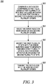
- FIG. 3 is a method performed in a transmitting device
- FIG. 4 is a method performed in a receiving device.
- the methods described by reference to figures 3 and 4 can be performed in the communication devices, the BS and a base station controller, for example, using a processing device that can comprise one or more of the processing devices described above such as, for instance, a DSP.
- a method 300 performed in a transmitting device includes a step 302 of generating a data block comprising a first field (e.g., 210) having a first plurality of bits that includes an error detection portion (e.g., 214) indicating an error detection value based on another portion (e.g., 212) of the first plurality of bits and used for error detection in decoding the other portion (212) of the first plurality of bits, and the data block further comprising a second field (e.g., 220) having a second plurality of bits (not shown in FIG. 3 ).
- the error detection value is identified or indicated by the bits ("e") in the error detection portion 214 of field 210, and this value is calculated based on the type of error detection technique used in the transmitting device.
- an error injection mask is selected based on the second plurality of bits in field 220.
- the error injection mask can be implemented in any number of forms, but in general comprises a predetermined number of bits representing a particular mask value.
- the mask value corresponds to the value represented by the bits included in field 220.
- N the number of different values that can be represented as bit values in the second field
- the first plurality of bits is "modified” with the error injection mask to generate a "modified” first plurality of bits that is used for error detection in decoding the second plurality of bits.
- the phrase "modifying the first plurality of bits with an error injection mask” is used synonymously with the phrase “applying an error injection mask to the first plurality of bits", and both refer in general to processing whereby at least a portion of the first plurality of bits in the field 210 is combined with an error injection mask (value) using some type of arithmetic operation.
- other type of arithmetic could be used such as, for instance, Galois Field arithmetic.
- modified first plurality of bits does not necessarily mean that one or more bit values in the first plurality of bits is changed after applying the error injection mask, even though this is usually the case. This is because an error injection mask having a value of zero may be selected, which would result in no change to the first plurality of bits. Accordingly, "modified first plurality of bits” means that the error injection mask has been applied to the first plurality of bits, irrespective of whether it resulted in a bit value being changed.
- FIG. 4 illustrates a method 400 performed in radio 104 upon (at a step 402) receiving the data block 200 having the error injection mask applied to the first plurality of bits included in field 210, and the data block 200 further having field 220 with the second plurality of bits.
- the receiving device decodes the second plurality of bits to generate decoding results for the field 220.
- decoding means identifying the bits and, usually, also at least includes performing some type of error correction on the received bits. Any type of decoding process may be used in conjunction with the teachings herein, including, but not limited to those listed above.
- an error injection mask is selected that corresponds to the decoding results from field 220.
- the first plurality of bits in field 210 are modified using the selected error injection mask to generate a modified first plurality of bits. Based upon these modified first plurality of bits, it can be (at a step 410) determined (among other things) whether the decoding results are correct using, for instance, further processing techniques as discussed below.
- an error detection calculation can be performed on just some of the bits (e.g., 212) in the modified first plurality of bits and the calculated error detection value compared to the error detection value that was in field 210 of the received data block prior to the error detection calculation.
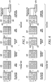
- This implementation is illustrated with respect to the embodiments shown in figures 5 through 9 . For simplicity of illustration, only field 210 of data block 200 is shown since this is the field to which the mask is applied and upon which error detection calculations are made.
- an error detection calculation can be performed on all modified first plurality of bits inclusive of the error detection bits, and the calculated error detection value compared to a predetermined value (e.g., a zero value).
- field 210 in data block 200 is being processed in accordance with the teachings herein.
- field 210 is shown as having a different reference number as a result of the error injection mask being applied thereto.
- FIG. 5 an embodiment is shown wherein, in the transmitting device, a selected error injection mask 520 (which is selected based on the bit values in field 220) is combined (using bitwise modulo 2 addition) with the data bits 212 and error detection bits 214 in field 210 to modify only the error detection bits 214, resulting in a modified field 530.
- Data block 200 including field 530 and field 220 is transmitted and received in the receiving device.
- a selected error injection mask 550 (which is selected based on the decoded bit values in field 220) is combined (using bitwise modulo 2 addition) with the data bits 532 and error detection bits 534 in field 530 to modify only the error detection bits 534, resulting in a modified field 560.
- An error detection calculation (in this example a Checksum calculation) is applied to data bits 562 and a calculated Checksum 570 is compared to error detection bits 564. If the two values are equal, then it can be concluded that field 220 was properly decoded, and normal processing can be continued in the receiving device, which is dependent on the type of data block received.
- the two values are not equal, then it can be concluded that an error has occurred (e.g., in decoding the bits in field 220, in decoding the data bits 532, or both) and the receiving device performs error handling including, but not limited to, discarding the received data block and sending a NACK (negative acknowledgement message) to the transmitting device or just simply discarding the received data block.
- the results indicate that field 220 has been properly decoded.
- a selected error injection mask 620 (which is selected based on the bit values in field 220) is combined (using bitwise modulo 2 addition) with the data bits 212 and error detection bits 214 in field 210 to modify only the data bits 212, resulting in a modified field 630.
- Data block 200 including field 630 and field 220 is transmitted and received in the receiving device.
- a selected error injection mask 650 (which is selected based on the decoded bit values in field 220) is combined (using bitwise modulo 2 addition) with the data bits 632 and error detection bits 634 in field 630 to modify only the data bits 632, resulting in a modified field 660.
- An error detection calculation (in this example a Checksum calculation) is applied to data bits 662 and a calculated Checksum 670 is compared to error detection bits 664. If the two values are equal, then it can be concluded that field 220 was properly decoded, and normal processing can be continued in the receiving device, which is dependent on the type of data block received.
- the two values are not equal, then it can be concluded that an error has occurred (e.g., in decoding the bits in field 220, in decoding the data bits 632, or both) and the receiving device should perform error handling.
- the results indicate that field 220 has been properly decoded.
- a selected error injection mask 720 (which is selected based on the bit values in field 220) is combined (using bitwise modulo 2 addition) with the data bits 212 and error detection bits 214 in field 210 to modify both the data bits 212 and the error detection bits 214, resulting in a modified field 730.
- Data block 200 including field 730 and field 220 is transmitted and received in the receiving device.
- a selected error injection mask 750 (which is selected based on the decoded bit values in field 220) is combined (using bitwise modulo 2 addition) with the data bits 732 and error detection bits 734 in field 730 to modify both the data bits 732 and the error detection bits 734, resulting in a modified field 760.
- An error detection calculation (in this example a Checksum calculation) is applied to data bits 762 and a calculated Checksum 770 is compared to error detection bits 764. If the two values are equal, then it can be concluded that field 220 was properly decoded, and normal processing can be continued in the receiving device, which is dependent on the type of data block received.
- the two values are not equal, then it can be concluded that an error has occurred (e.g., in decoding the bits in field 220, in decoding the data bits 732, or both) and the receiving device should perform error handling.
- the results indicate that field 220 has been properly decoded.
- FIG. 8 an embodiment is shown wherein, in the transmitting device, a selected error injection mask 820 (which is selected based on the bit values in field 220) is combined (using bitwise modulo 2 addition) with the data bits 212 and error detection bits 214 in field 210 to modify both the data bits 212 and the error detection bits 214, resulting in a modified field 830.
- Data block 200 including field 830 and field 220 is transmitted and received in the receiving device.
- a selected error injection mask 850 (which is selected based on the decoded bit values in field 220) is combined (using bitwise modulo 2 addition) with the data bits 832 and error detection bits 834 in field 830 to modify both the data bits 832 and the error detection bits 834, resulting in a modified field 860.
- An error detection calculation (in this example a Checksum calculation) is applied to data bits 862 and a calculated Checksum 870 is compared to error detection bits 864. If the two values are equal, then it can be concluded that field 220 was properly decoded, and normal processing can be continued in the receiving device, which is dependent on the type of data block received.
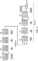
- multiples masks are applied to the data bits 212 and error detection bits 214 of field 220 to detect errors in decoding the bits of multiple fields in data block 200, each of which have no error detection bits or limited error detection bits.
- two masks are applied (one corresponding to field 220 and the other corresponding to field 230).
- any number of masks can be applied based on the teachings herein.
- selected error injection masks 920 (which is selected based on the bit values in field 220) and 925 (which is selected based on the bit values in field 230) are combined (using bitwise modulo 2 addition) with the data bits 212 and error detection bits 214 in field 210 to modify both the data bits 212 and the error detection bits 214, resulting in a modified field 930.
- Data block 200 including field 930 and fields 220 and 230 is transmitted and received in the receiving device.
- selected error injection masks 940 (which is selected based on the decoded bit values in field 220) and 950 (which is selected based on the decoded bit values in field 230) are combined (using bitwise modulo 2 addition) with the data bits 932 and error detection bits 934 in field 930 to modify both the data bits 932 and the error detection bits 934, resulting in a modified field 960.
- An error detection calculation (in this example a Checksum calculation) is applied to data bits 962 and a calculated Checksum 970 is compared to error detection bits 964. If the two values are equal, then it can be concluded that field 220 was properly decoded, and normal processing can be continued in the receiving device, which is dependent on the type of data block received.
- the two values are not equal, then it can be concluded that an error has occurred (e.g., in decoding the bits in fields 220 or 230, in decoding the data bits 832, or any combination of the three) and the receiving device should perform error handling.
- the results indicate that fields 220 and 230 have been properly decoded.
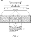
- FIG. 10 illustrates an exemplary DMR Data and Control burst as defined in ETSI TS 102 361-1 .
- the data and control burst contains an Info field 1010 containing 196 bits of information.
- the information consists of Link Control (LC) 1016, error detection (CRC) 1018, and Block Product Turbo Code (BPTC) FEC parity (not shown) added by BPTC (196, 96) Encoder 1014.
- the data and control burst also contains a 20-bit Slot Type field 1020 that defines the meaning of the information bits.
- the Slot Type field includes a Color Code (CC) Field 1022, a Data Type field 1024, and FEC Parity 1026 in accordance with ETSI TS 102 361-1 .
- CC Color Code
- the Data Type field 1024 could be set to Voice LC Header.
- the center of the burst contains either a synchronization pattern or embedded signaling information field 1030 in accordance with ETSI TS 102 361-1 .
- an Interleaver 1012 in accordance with ETSI TS 102 361-1 .
- a transmitting device generates a DMR TDMA burst 1000 in accordance with the teachings herein that enables error detection of data type bits 1024 in the Slot Type field 1020 using the error detection mechanism in the Information field 1010.
- a transmitting device generates a DMR TDMA burst 1000 in accordance with the teachings herein that enables error detection of data type bits 1024 in the Slot Type field 1020 using the error detection mechanism in the Information field 1010.
- the data and/or error detection parity in Information field 1010 are "modified" in accordance with the teachings herein, and the generation of bits for the remaining fields shown in FIG. 10 are as disclosed in ETSI TS 102 361-1 , the generation of which will not be further described herein for the sake of brevity.
- the data type bits 1024 and data bits (in this case LC bits) 1016 are generated and accepted, respectively, into the Slot Type field 1020 and the Information field 1010 of burst 1000.
- error detection parity e.g., CRC
- the transmitting device selects an error injection mask for the specified data type bits 1024 accepted at step 1102.
- the selected error injection mask is applied (using bitwise modulo 2 addition for example) to the LC data bits 1016 and CRC parity 1018 to generate modified LC data bits 1016 and/or CRC parity 1018.
- the transmitting device transmits to a receiving device the burst 1000 that includes (among other fields with their corresponding bits, of course) the Slot Type Field 1020 including the data type bits 1024 and the Information Field 1010 including the modified LC data bits 1016 and/or CRC parity 1018.
- step 1108 and 1110 of selecting and applying an error injection mask Each data type already designated in ETSI TS 102 361-1 is assigned a predetermined error injection mask. Additional error injection masks may also be predetermined and reserved for future data types. Tables 1 and 2 below show exemplary error injection masks that may be assigned to present and future data types. These exemplary data mask are selected based on the specified data type from the table and applied to Information field 1010 to modify only the CRC parity 1018. In this case, since the data type is Voice LC Header the error injection mask 969696 16 corresponding to Voice LC Header is selected and applied to Information field 1010 to modify CRC parity 1018.
- error injection masks may be predetermined that would modify only the LC data bits 1016 or both LC data bits 1016 and the CRC parity 1018.
- Table 1 Data Type 8-bit Mask (base 16) 9-bit Mask (base 8) 16-bit Mask (base 16) PI Header 0 69 551 6969 Voice LC Header 1 96 226 9696 Terminator with LC 2 99 631 9999 CSBK 3 a5 645 a5a5 MBC Header 4 aa 252 aaaa MBC Continuation 5 c3 703 c3c3 Data Header 6 cc 314 cccc Rate 1 ⁇ 2 Data Continuation 7 f0 360 fOfO Rate % Data Continuation 8 ff 777 ffff Idle 9 00 000 0000 Reserved for future use a 0f 417 0f0f Reserved for future use b 33 463 3333 Reserved for future use c
- error detection for at least one other field in the burst can be performed using the error detection mechanism of the Information field 1010.
- another field that has no error detection and which can be a second field for which error detection can be performed using the error detection of Information field 1010 is the Color Code (CC) field 922.
- CC Color Code
- a second set of predetermined masks e.g., shown in Tables 3 and 4 below, can be used to facilitate error detection in the CC field in accordance with the teachings above. Accordingly, at the transmitter device both masks would be applied to modify the CRC parity and two selected masks would be applied at the receiving device to again modify the CRC parity. Error detection could then be performed similar to that described below by reference to FIG. 12 .
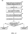
- the receiving device receives the burst 1000 from the transmitting device that includes (among other fields with their corresponding bits, of course) the Slot Type Field 1020 including the data type bits 1024 and the Information Field 1010 including the modified LC data bits 1016 and/or CRC parity 1018.
- the receiving device decodes the data type bits 1024 in the Slot Type field 1020 to identify the data type for the data bits 1016 in the Information field 1010 of the received burst 1000.
- the receiving device uses a (196, 96) BPTC Decoder to decode the bits that were encoded by the (196, 96) BPTC Encoder in the transmitting device.
- the receiving device selects the error injection mask corresponding to the decoded data type bits 1024. If the receiver decodes the data type correctly, it will select the error injection mask corresponding to Voice LC Header data type (in this case 969696 16 ).
- the receiving device applies the selected error injection mask (using bitwise modulo 2 arithmetic) to the data bits 1016 and CRC parity 1018, at a step 1208, to (in this case) modify the CRC parity 1018.
- the receiving device performs an error detection calculation, at a step 1210, (in this case a CRC calculation) on the modified Information field. From the CRC calculation, at a step 1212, the receiving device determines whether to continue normal processing at a step 1216 when the CRC calculation indicate no decoding errors in decoding the data type bits 1024 and in decoding the LC bits 1016. If the CRC calculation indicates a decoding error (which could be in either the data type or data bits), the receiving device performs error handling at a step 1214, for instance, in a manner as discussed above.
- the CRC will so indicate, with the particular indication depending on how the CRC calculation was performed.
- the CRC calculation can be performed on just the LC data bits 1016 and a comparison made between the calculated CRC and the CRC bits 1018 prior to the Information field being modified using the error injection mask. Where the two values are equal, this indicates that the receiving device correctly decoded the data type bits 1024 and correctly decoded the LC bits 1016. A difference in the values similarly indicates that the CRC bits 1018 and/or the LC bits 1018 were incorrectly decoded.
- the CRC calculation can be performed on both the LC data bits 1016 and the current CRC bits 1018 and a comparison made between the calculated CRC and a predetermined bit value such as zero. Where the calculated CRC is zero, this indicates that the receiving device correctly decoded the data type bits 1024 and correctly decoded the LC bits 1016. A CRC other than zero indicates that the CRC bits 1018 and/or the LC bits 1018 were incorrectly decoded.
- a "contains ... a” does not, without more constraints, preclude the existence of additional identical elements in the process, method, article, or apparatus that comprises, has, includes, contains the element.
- the terms “a” and “an” are defined as one or more unless explicitly stated otherwise herein.
- the terms “substantially”, “essentially”, “approximately”, “about” or any other version thereof, are defined as being close to as understood by one of ordinary skill in the art, and in one non-limiting embodiment the term is defined to be within 10%, in another embodiment within 5%, in another embodiment within 1% and in another embodiment within 0.5%.
- the term “coupled” as used herein is defined as connected, although not necessarily directly and not necessarily mechanically.
- a device or structure that is “configured” in a certain way is configured in at least that way, but may also be configured in ways that are not listed.
Landscapes
- Engineering & Computer Science (AREA)
- Computer Networks & Wireless Communication (AREA)
- Signal Processing (AREA)
- Physics & Mathematics (AREA)
- Probability & Statistics with Applications (AREA)
- Theoretical Computer Science (AREA)
- Detection And Prevention Of Errors In Transmission (AREA)
- Error Detection And Correction (AREA)
- Mobile Radio Communication Systems (AREA)
Priority Applications (1)
| Application Number | Priority Date | Filing Date | Title |
|---|---|---|---|
| PL07799864T PL2052482T3 (pl) | 2006-08-14 | 2007-07-27 | Sposób i urządzenie do wykrywania błędów w bloku danych |
Applications Claiming Priority (2)
| Application Number | Priority Date | Filing Date | Title |
|---|---|---|---|
| US11/464,369 US7500170B2 (en) | 2006-08-14 | 2006-08-14 | Method and apparatus for error detection in a data block |
| PCT/US2007/074539 WO2008021693A2 (en) | 2006-08-14 | 2007-07-27 | Method and apparatus for error detection in a data block |
Publications (3)
| Publication Number | Publication Date |
|---|---|
| EP2052482A2 EP2052482A2 (en) | 2009-04-29 |
| EP2052482A4 EP2052482A4 (en) | 2009-09-09 |
| EP2052482B1 true EP2052482B1 (en) | 2017-09-06 |
Family
ID=39082862
Family Applications (1)
| Application Number | Title | Priority Date | Filing Date |
|---|---|---|---|
| EP07799864.9A Active EP2052482B1 (en) | 2006-08-14 | 2007-07-27 | Method and apparatus for error detection in a data block |
Country Status (13)
| Country | Link |
|---|---|
| US (1) | US7500170B2 (pl) |
| EP (1) | EP2052482B1 (pl) |
| JP (1) | JP5282574B2 (pl) |
| CN (1) | CN101411109B (pl) |
| AU (1) | AU2007284221B2 (pl) |
| BR (1) | BRPI0708491B1 (pl) |
| CA (1) | CA2642102C (pl) |
| ES (1) | ES2651194T3 (pl) |
| MX (1) | MX2008010665A (pl) |
| NZ (1) | NZ570506A (pl) |
| PL (1) | PL2052482T3 (pl) |
| RU (1) | RU2392750C1 (pl) |
| WO (1) | WO2008021693A2 (pl) |
Families Citing this family (23)
| Publication number | Priority date | Publication date | Assignee | Title |
|---|---|---|---|---|
| US8181100B1 (en) * | 2008-02-07 | 2012-05-15 | Marvell International Ltd. | Memory fault injection |
| US8411662B1 (en) | 2005-10-04 | 2013-04-02 | Pico Mobile Networks, Inc. | Beacon based proximity services |
| US7568137B1 (en) * | 2007-03-27 | 2009-07-28 | Xilinx, Inc. | Method and apparatus for a clock and data recovery circuit |
| EP2153204A4 (en) * | 2007-06-07 | 2016-06-15 | Afl Telecommunications Llc | METHOD FOR DETECTING LIGHT FILTERS AND BANDS |
| US20140281761A1 (en) * | 2008-03-11 | 2014-09-18 | Peter Lablans | Reversible corruption of a digital medium stream by multi-valued modification in accordance with an automatically generated mask |
| US8627163B2 (en) * | 2008-03-25 | 2014-01-07 | Micron Technology, Inc. | Error-correction forced mode with M-sequence |
| EP2151940A1 (en) * | 2008-08-05 | 2010-02-10 | Nokia Siemens Networks OY | Communication network element and method transmitting data |
| US8892983B2 (en) * | 2008-11-04 | 2014-11-18 | Alcatel Lucent | Method and apparatus for error detection in a communication system |
| US8438452B2 (en) | 2008-12-29 | 2013-05-07 | Intel Corporation | Poison bit error checking code scheme |
| US8281216B2 (en) * | 2009-03-31 | 2012-10-02 | Motorola Solutions, Inc. | Method for assigning and utilizing forward error correcting (FEC) codes |
| US8949801B2 (en) * | 2009-05-13 | 2015-02-03 | International Business Machines Corporation | Failure recovery for stream processing applications |
| US8566688B2 (en) * | 2009-09-01 | 2013-10-22 | Ensequence, Inc. | Method of certifying multiple versions of an application |
| US9380401B1 (en) | 2010-02-03 | 2016-06-28 | Marvell International Ltd. | Signaling schemes allowing discovery of network devices capable of operating in multiple network modes |
| US8458650B2 (en) * | 2010-03-29 | 2013-06-04 | International Business Machines Corporation | Injecting a fault into a stream operator in a data stream processing application |
| CN102263612B (zh) * | 2011-07-18 | 2014-12-17 | 杭州承联通信技术有限公司 | 用于数据块的差错检测方法和设备 |
| US9749448B2 (en) * | 2014-11-25 | 2017-08-29 | Intel Corporation | Header parity error handling |
| US9942895B2 (en) * | 2015-07-31 | 2018-04-10 | Hughes Network Systems, Llc | Burst grouping with reduced overhead |
| CN108572788A (zh) * | 2017-03-13 | 2018-09-25 | 广州市动景计算机科技有限公司 | 数据存取方法、装置及系统 |
| US11047766B2 (en) | 2018-04-11 | 2021-06-29 | Afl Telecommunications Llc | Systems and methods for identification and testing of optical fibers |
| US11937244B2 (en) * | 2018-09-28 | 2024-03-19 | Telefonaktiebolagget LM Ericsson (Publ) | Uplink control information for unlicensed operation |
| US11152953B2 (en) * | 2020-02-28 | 2021-10-19 | Qualcomm Incorporated | Error detection for a wireless channel |
| CN115019862B (zh) * | 2021-03-04 | 2026-01-13 | 瑞昱半导体股份有限公司 | 静态随机存取存储器的纠错电路的验证方法 |
| US11762736B2 (en) | 2021-05-18 | 2023-09-19 | Samsung Electronics Co., Ltd. | Semiconductor memory devices |
Family Cites Families (15)
| Publication number | Priority date | Publication date | Assignee | Title |
|---|---|---|---|---|
| JPH04245819A (ja) * | 1991-01-31 | 1992-09-02 | Pioneer Electron Corp | 誤り訂正機能を備えた情報信号伝送装置 |
| SE501340C2 (sv) * | 1993-06-11 | 1995-01-23 | Ericsson Telefon Ab L M | Döljande av transmissionsfel i en talavkodare |
| JPH08195736A (ja) * | 1995-01-13 | 1996-07-30 | Nec Corp | 通信システム |
| US5574855A (en) * | 1995-05-15 | 1996-11-12 | Emc Corporation | Method and apparatus for testing raid systems |
| US5931967A (en) * | 1996-02-22 | 1999-08-03 | Fujitsu, Ltd. | Method and apparatus for detection of errors in multiple-word communications |
| JP2002517060A (ja) * | 1998-05-27 | 2002-06-11 | クロジック コーポレーション | エラー比較システム |
| US6233073B1 (en) * | 1998-07-30 | 2001-05-15 | International Business Machines Corporation | Diagnostic injection of transmission errors in fiber optic networks |
| US6631481B1 (en) * | 2000-02-16 | 2003-10-07 | International Business Machines Corporation | Method and apparatus for injecting an error into a waveform sent over a data link |
| KR100833222B1 (ko) * | 2000-03-29 | 2008-05-28 | 삼성전자주식회사 | 멀티미디어 송수신 장치 및 방법 |
| US6622268B2 (en) * | 2000-11-29 | 2003-09-16 | Intel Corp | Method and apparatus for propagating error status over an ECC protected channel |
| US6751756B1 (en) * | 2000-12-01 | 2004-06-15 | Unisys Corporation | First level cache parity error inject |
| US6704894B1 (en) * | 2000-12-21 | 2004-03-09 | Lockheed Martin Corporation | Fault insertion using on-card reprogrammable devices |
| FR2854512B1 (fr) * | 2003-04-30 | 2005-07-08 | Nortel Networks Ltd | Procede et dispositif de reception de blocs de donnees |
| CN1716211A (zh) * | 2004-07-02 | 2006-01-04 | 中国科学院上海微系统与信息技术研究所 | 数据差错检测和纠正用的交叉正反编码结构和解码的方法 |
| US7669095B2 (en) * | 2006-02-01 | 2010-02-23 | International Business Machines Corporation | Methods and apparatus for error injection |
-
2006
- 2006-08-14 US US11/464,369 patent/US7500170B2/en active Active
-
2007
- 2007-07-27 NZ NZ570506A patent/NZ570506A/en unknown
- 2007-07-27 EP EP07799864.9A patent/EP2052482B1/en active Active
- 2007-07-27 JP JP2008556589A patent/JP5282574B2/ja active Active
- 2007-07-27 MX MX2008010665A patent/MX2008010665A/es active IP Right Grant
- 2007-07-27 AU AU2007284221A patent/AU2007284221B2/en active Active
- 2007-07-27 CA CA2642102A patent/CA2642102C/en active Active
- 2007-07-27 ES ES07799864.9T patent/ES2651194T3/es active Active
- 2007-07-27 WO PCT/US2007/074539 patent/WO2008021693A2/en not_active Ceased
- 2007-07-27 CN CN2007800104672A patent/CN101411109B/zh active Active
- 2007-07-27 PL PL07799864T patent/PL2052482T3/pl unknown
- 2007-07-27 BR BRPI0708491-9A patent/BRPI0708491B1/pt active IP Right Grant
- 2007-07-27 RU RU2008145754/09A patent/RU2392750C1/ru active
Also Published As
| Publication number | Publication date |
|---|---|
| PL2052482T3 (pl) | 2018-02-28 |
| JP2009528728A (ja) | 2009-08-06 |
| RU2392750C1 (ru) | 2010-06-20 |
| EP2052482A4 (en) | 2009-09-09 |
| BRPI0708491B1 (pt) | 2019-11-19 |
| CA2642102C (en) | 2011-12-20 |
| ES2651194T3 (es) | 2018-01-24 |
| CN101411109B (zh) | 2013-08-14 |
| MX2008010665A (es) | 2008-09-01 |
| EP2052482A2 (en) | 2009-04-29 |
| AU2007284221A1 (en) | 2008-02-21 |
| US7500170B2 (en) | 2009-03-03 |
| BRPI0708491A2 (pt) | 2011-05-31 |
| WO2008021693A2 (en) | 2008-02-21 |
| NZ570506A (en) | 2010-09-30 |
| CA2642102A1 (en) | 2008-02-21 |
| JP5282574B2 (ja) | 2013-09-04 |
| WO2008021693A3 (en) | 2008-11-06 |
| AU2007284221B2 (en) | 2009-12-10 |
| US20080052603A1 (en) | 2008-02-28 |
| CN101411109A (zh) | 2009-04-15 |
Similar Documents
| Publication | Publication Date | Title |
|---|---|---|
| EP2052482B1 (en) | Method and apparatus for error detection in a data block | |
| JP2661368B2 (ja) | 送信されたデータ語の誤り訂正方法 | |
| US6868520B1 (en) | Method and apparatus for providing high quality transmissions in a telecommunications system | |
| EP1357691B1 (en) | A method for encoding a user identifier in a communication system | |
| AU755043B2 (en) | Data transmission method, data transmission system, transmitter and receiver | |
| CN101803208A (zh) | 无线通信系统中的多层循环冗余校验码 | |
| WO2008117164A2 (en) | Encoding and decoding systems with header and data transmission success indication | |
| US6658064B1 (en) | Method for transmitting background noise information in data transmission in data frames | |
| US20040199848A1 (en) | Error correction decoding apparatus and error correction decoding method | |
| US20100260292A1 (en) | Blind modulation detection | |
| JPH10327089A (ja) | 携帯電話装置 | |
| US20080186943A1 (en) | System and method for processing data and control messages in a communication system | |
| US20030007487A1 (en) | Method and an apparatus for use of codes in multicast transmission | |
| US20170164271A1 (en) | Systems and methods for communicating half-rate encoded voice frames | |
| US6883130B2 (en) | Enhanced and adaptive error detection in digital communications | |
| CN101001127B (zh) | 对传输信息做校验和编码的设备和方法 | |
| EP3605851A1 (en) | Iterative decoding using re-encoding between decoding stages | |
| JP4531985B2 (ja) | Gsm移動無線システムにおける通信路符号化方法ならびに基地局および加入者局 |
Legal Events
| Date | Code | Title | Description |
|---|---|---|---|
| PUAI | Public reference made under article 153(3) epc to a published international application that has entered the european phase |
Free format text: ORIGINAL CODE: 0009012 |
|
| 17P | Request for examination filed |
Effective date: 20081009 |
|
| AK | Designated contracting states |
Kind code of ref document: A2 Designated state(s): AT BE BG CH CY CZ DE DK EE ES FI FR GB GR HU IE IS IT LI LT LU LV MC MT NL PL PT RO SE SI SK TR |
|
| AX | Request for extension of the european patent |
Extension state: AL BA HR MK RS |
|
| A4 | Supplementary search report drawn up and despatched |
Effective date: 20090810 |
|
| DAX | Request for extension of the european patent (deleted) | ||
| 17Q | First examination report despatched |
Effective date: 20091228 |
|
| RAP1 | Party data changed (applicant data changed or rights of an application transferred) |
Owner name: MOTOROLA SOLUTIONS, INC. |
|
| RAP1 | Party data changed (applicant data changed or rights of an application transferred) |
Owner name: MOTOROLA SOLUTIONS, INC. |
|
| GRAP | Despatch of communication of intention to grant a patent |
Free format text: ORIGINAL CODE: EPIDOSNIGR1 |
|
| STAA | Information on the status of an ep patent application or granted ep patent |
Free format text: STATUS: GRANT OF PATENT IS INTENDED |
|
| INTG | Intention to grant announced |
Effective date: 20170307 |
|
| GRAS | Grant fee paid |
Free format text: ORIGINAL CODE: EPIDOSNIGR3 |
|
| GRAA | (expected) grant |
Free format text: ORIGINAL CODE: 0009210 |
|
| STAA | Information on the status of an ep patent application or granted ep patent |
Free format text: STATUS: THE PATENT HAS BEEN GRANTED |
|
| AK | Designated contracting states |
Kind code of ref document: B1 Designated state(s): AT BE BG CH CY CZ DE DK EE ES FI FR GB GR HU IE IS IT LI LT LU LV MC MT NL PL PT RO SE SI SK TR |
|
| REG | Reference to a national code |
Ref country code: GB Ref legal event code: FG4D |
|
| REG | Reference to a national code |
Ref country code: CH Ref legal event code: EP Ref country code: AT Ref legal event code: REF Ref document number: 926951 Country of ref document: AT Kind code of ref document: T Effective date: 20170915 |
|
| REG | Reference to a national code |
Ref country code: IE Ref legal event code: FG4D |
|
| REG | Reference to a national code |
Ref country code: DE Ref legal event code: R096 Ref document number: 602007052293 Country of ref document: DE |
|
| REG | Reference to a national code |
Ref country code: NL Ref legal event code: FP |
|
| REG | Reference to a national code |
Ref country code: ES Ref legal event code: FG2A Ref document number: 2651194 Country of ref document: ES Kind code of ref document: T3 Effective date: 20180124 |
|
| REG | Reference to a national code |
Ref country code: LT Ref legal event code: MG4D |
|
| PG25 | Lapsed in a contracting state [announced via postgrant information from national office to epo] |
Ref country code: FI Free format text: LAPSE BECAUSE OF FAILURE TO SUBMIT A TRANSLATION OF THE DESCRIPTION OR TO PAY THE FEE WITHIN THE PRESCRIBED TIME-LIMIT Effective date: 20170906 Ref country code: LT Free format text: LAPSE BECAUSE OF FAILURE TO SUBMIT A TRANSLATION OF THE DESCRIPTION OR TO PAY THE FEE WITHIN THE PRESCRIBED TIME-LIMIT Effective date: 20170906 Ref country code: SE Free format text: LAPSE BECAUSE OF FAILURE TO SUBMIT A TRANSLATION OF THE DESCRIPTION OR TO PAY THE FEE WITHIN THE PRESCRIBED TIME-LIMIT Effective date: 20170906 |
|
| REG | Reference to a national code |
Ref country code: AT Ref legal event code: MK05 Ref document number: 926951 Country of ref document: AT Kind code of ref document: T Effective date: 20170906 |
|
| PG25 | Lapsed in a contracting state [announced via postgrant information from national office to epo] |
Ref country code: BG Free format text: LAPSE BECAUSE OF FAILURE TO SUBMIT A TRANSLATION OF THE DESCRIPTION OR TO PAY THE FEE WITHIN THE PRESCRIBED TIME-LIMIT Effective date: 20171206 Ref country code: GR Free format text: LAPSE BECAUSE OF FAILURE TO SUBMIT A TRANSLATION OF THE DESCRIPTION OR TO PAY THE FEE WITHIN THE PRESCRIBED TIME-LIMIT Effective date: 20171207 Ref country code: LV Free format text: LAPSE BECAUSE OF FAILURE TO SUBMIT A TRANSLATION OF THE DESCRIPTION OR TO PAY THE FEE WITHIN THE PRESCRIBED TIME-LIMIT Effective date: 20170906 |
|
| PG25 | Lapsed in a contracting state [announced via postgrant information from national office to epo] |
Ref country code: RO Free format text: LAPSE BECAUSE OF FAILURE TO SUBMIT A TRANSLATION OF THE DESCRIPTION OR TO PAY THE FEE WITHIN THE PRESCRIBED TIME-LIMIT Effective date: 20170906 Ref country code: CZ Free format text: LAPSE BECAUSE OF FAILURE TO SUBMIT A TRANSLATION OF THE DESCRIPTION OR TO PAY THE FEE WITHIN THE PRESCRIBED TIME-LIMIT Effective date: 20170906 |
|
| PG25 | Lapsed in a contracting state [announced via postgrant information from national office to epo] |
Ref country code: SK Free format text: LAPSE BECAUSE OF FAILURE TO SUBMIT A TRANSLATION OF THE DESCRIPTION OR TO PAY THE FEE WITHIN THE PRESCRIBED TIME-LIMIT Effective date: 20170906 Ref country code: IS Free format text: LAPSE BECAUSE OF FAILURE TO SUBMIT A TRANSLATION OF THE DESCRIPTION OR TO PAY THE FEE WITHIN THE PRESCRIBED TIME-LIMIT Effective date: 20180106 Ref country code: AT Free format text: LAPSE BECAUSE OF FAILURE TO SUBMIT A TRANSLATION OF THE DESCRIPTION OR TO PAY THE FEE WITHIN THE PRESCRIBED TIME-LIMIT Effective date: 20170906 Ref country code: EE Free format text: LAPSE BECAUSE OF FAILURE TO SUBMIT A TRANSLATION OF THE DESCRIPTION OR TO PAY THE FEE WITHIN THE PRESCRIBED TIME-LIMIT Effective date: 20170906 |
|
| REG | Reference to a national code |
Ref country code: DE Ref legal event code: R097 Ref document number: 602007052293 Country of ref document: DE |
|
| PLBE | No opposition filed within time limit |
Free format text: ORIGINAL CODE: 0009261 |
|
| STAA | Information on the status of an ep patent application or granted ep patent |
Free format text: STATUS: NO OPPOSITION FILED WITHIN TIME LIMIT |
|
| REG | Reference to a national code |
Ref country code: FR Ref legal event code: PLFP Year of fee payment: 12 |
|
| PG25 | Lapsed in a contracting state [announced via postgrant information from national office to epo] |
Ref country code: DK Free format text: LAPSE BECAUSE OF FAILURE TO SUBMIT A TRANSLATION OF THE DESCRIPTION OR TO PAY THE FEE WITHIN THE PRESCRIBED TIME-LIMIT Effective date: 20170906 |
|
| 26N | No opposition filed |
Effective date: 20180607 |
|
| PG25 | Lapsed in a contracting state [announced via postgrant information from national office to epo] |
Ref country code: SI Free format text: LAPSE BECAUSE OF FAILURE TO SUBMIT A TRANSLATION OF THE DESCRIPTION OR TO PAY THE FEE WITHIN THE PRESCRIBED TIME-LIMIT Effective date: 20170906 |
|
| REG | Reference to a national code |
Ref country code: CH Ref legal event code: PL |
|
| PG25 | Lapsed in a contracting state [announced via postgrant information from national office to epo] |
Ref country code: LU Free format text: LAPSE BECAUSE OF NON-PAYMENT OF DUE FEES Effective date: 20180727 Ref country code: MC Free format text: LAPSE BECAUSE OF FAILURE TO SUBMIT A TRANSLATION OF THE DESCRIPTION OR TO PAY THE FEE WITHIN THE PRESCRIBED TIME-LIMIT Effective date: 20170906 |
|
| REG | Reference to a national code |
Ref country code: BE Ref legal event code: MM Effective date: 20180731 |
|
| PG25 | Lapsed in a contracting state [announced via postgrant information from national office to epo] |
Ref country code: CH Free format text: LAPSE BECAUSE OF NON-PAYMENT OF DUE FEES Effective date: 20180731 Ref country code: LI Free format text: LAPSE BECAUSE OF NON-PAYMENT OF DUE FEES Effective date: 20180731 |
|
| REG | Reference to a national code |
Ref country code: IE Ref legal event code: MM4A |
|
| PG25 | Lapsed in a contracting state [announced via postgrant information from national office to epo] |
Ref country code: BE Free format text: LAPSE BECAUSE OF NON-PAYMENT OF DUE FEES Effective date: 20180731 |
|
| PG25 | Lapsed in a contracting state [announced via postgrant information from national office to epo] |
Ref country code: IE Free format text: LAPSE BECAUSE OF NON-PAYMENT OF DUE FEES Effective date: 20180727 |
|
| PG25 | Lapsed in a contracting state [announced via postgrant information from national office to epo] |
Ref country code: MT Free format text: LAPSE BECAUSE OF NON-PAYMENT OF DUE FEES Effective date: 20180727 |
|
| PG25 | Lapsed in a contracting state [announced via postgrant information from national office to epo] |
Ref country code: TR Free format text: LAPSE BECAUSE OF FAILURE TO SUBMIT A TRANSLATION OF THE DESCRIPTION OR TO PAY THE FEE WITHIN THE PRESCRIBED TIME-LIMIT Effective date: 20170906 |
|
| PG25 | Lapsed in a contracting state [announced via postgrant information from national office to epo] |
Ref country code: PT Free format text: LAPSE BECAUSE OF FAILURE TO SUBMIT A TRANSLATION OF THE DESCRIPTION OR TO PAY THE FEE WITHIN THE PRESCRIBED TIME-LIMIT Effective date: 20170906 Ref country code: HU Free format text: LAPSE BECAUSE OF FAILURE TO SUBMIT A TRANSLATION OF THE DESCRIPTION OR TO PAY THE FEE WITHIN THE PRESCRIBED TIME-LIMIT; INVALID AB INITIO Effective date: 20070727 |
|
| PG25 | Lapsed in a contracting state [announced via postgrant information from national office to epo] |
Ref country code: CY Free format text: LAPSE BECAUSE OF FAILURE TO SUBMIT A TRANSLATION OF THE DESCRIPTION OR TO PAY THE FEE WITHIN THE PRESCRIBED TIME-LIMIT Effective date: 20170906 |
|
| P01 | Opt-out of the competence of the unified patent court (upc) registered |
Effective date: 20230523 |
|
| PGFP | Annual fee paid to national office [announced via postgrant information from national office to epo] |
Ref country code: PL Payment date: 20250623 Year of fee payment: 19 |
|
| PGFP | Annual fee paid to national office [announced via postgrant information from national office to epo] |
Ref country code: GB Payment date: 20250619 Year of fee payment: 19 |
|
| PGFP | Annual fee paid to national office [announced via postgrant information from national office to epo] |
Ref country code: NL Payment date: 20250620 Year of fee payment: 19 |
|
| PGFP | Annual fee paid to national office [announced via postgrant information from national office to epo] |
Ref country code: FR Payment date: 20250620 Year of fee payment: 19 |
|
| PGFP | Annual fee paid to national office [announced via postgrant information from national office to epo] |
Ref country code: ES Payment date: 20250801 Year of fee payment: 19 |
|
| PGFP | Annual fee paid to national office [announced via postgrant information from national office to epo] |
Ref country code: DE Payment date: 20250620 Year of fee payment: 19 |
|
| PGFP | Annual fee paid to national office [announced via postgrant information from national office to epo] |
Ref country code: IT Payment date: 20250619 Year of fee payment: 19 |
|
| REG | Reference to a national code |
Ref country code: DE Ref legal event code: R082 Ref document number: 602007052293 Country of ref document: DE Representative=s name: PUSCHMANN BORCHERT KAISER KLETTNER PATENTANWAE, DE Ref country code: DE Ref legal event code: R082 Ref document number: 602007052293 Country of ref document: DE Representative=s name: PATCARE PATENTANWAELTE PARTNERSCHAFT MBB, DE |