EP2052662A2 - Verfahren zur Steuerung einer Geschirrspülmaschine - Google Patents
Verfahren zur Steuerung einer Geschirrspülmaschine Download PDFInfo
- Publication number
- EP2052662A2 EP2052662A2 EP08253427A EP08253427A EP2052662A2 EP 2052662 A2 EP2052662 A2 EP 2052662A2 EP 08253427 A EP08253427 A EP 08253427A EP 08253427 A EP08253427 A EP 08253427A EP 2052662 A2 EP2052662 A2 EP 2052662A2
- Authority
- EP
- European Patent Office
- Prior art keywords
- washing water
- dishes
- sump
- washing
- dishwasher
- Prior art date
- Legal status (The legal status is an assumption and is not a legal conclusion. Google has not performed a legal analysis and makes no representation as to the accuracy of the status listed.)
- Withdrawn
Links
Images

Classifications
-
- A—HUMAN NECESSITIES
- A47—FURNITURE; DOMESTIC ARTICLES OR APPLIANCES; COFFEE MILLS; SPICE MILLS; SUCTION CLEANERS IN GENERAL
- A47L—DOMESTIC WASHING OR CLEANING; SUCTION CLEANERS IN GENERAL
- A47L15/00—Washing or rinsing machines for crockery or tableware
- A47L15/42—Details
- A47L15/46—Devices for the automatic control of the different phases of cleaning ; Controlling devices
-
- A—HUMAN NECESSITIES
- A47—FURNITURE; DOMESTIC ARTICLES OR APPLIANCES; COFFEE MILLS; SPICE MILLS; SUCTION CLEANERS IN GENERAL
- A47L—DOMESTIC WASHING OR CLEANING; SUCTION CLEANERS IN GENERAL
- A47L15/00—Washing or rinsing machines for crockery or tableware
- A47L15/0018—Controlling processes, i.e. processes to control the operation of the machine characterised by the purpose or target of the control
- A47L15/0021—Regulation of operational steps within the washing processes, e.g. optimisation or improvement of operational steps depending from the detergent nature or from the condition of the crockery
- A47L15/0031—Water discharge phases
-
- A—HUMAN NECESSITIES
- A47—FURNITURE; DOMESTIC ARTICLES OR APPLIANCES; COFFEE MILLS; SPICE MILLS; SUCTION CLEANERS IN GENERAL
- A47L—DOMESTIC WASHING OR CLEANING; SUCTION CLEANERS IN GENERAL
- A47L15/00—Washing or rinsing machines for crockery or tableware
- A47L15/0018—Controlling processes, i.e. processes to control the operation of the machine characterised by the purpose or target of the control
- A47L15/0021—Regulation of operational steps within the washing processes, e.g. optimisation or improvement of operational steps depending from the detergent nature or from the condition of the crockery
- A47L15/0023—Water filling
-
- A—HUMAN NECESSITIES
- A47—FURNITURE; DOMESTIC ARTICLES OR APPLIANCES; COFFEE MILLS; SPICE MILLS; SUCTION CLEANERS IN GENERAL
- A47L—DOMESTIC WASHING OR CLEANING; SUCTION CLEANERS IN GENERAL
- A47L15/00—Washing or rinsing machines for crockery or tableware
- A47L15/42—Details
-
- A—HUMAN NECESSITIES
- A47—FURNITURE; DOMESTIC ARTICLES OR APPLIANCES; COFFEE MILLS; SPICE MILLS; SUCTION CLEANERS IN GENERAL
- A47L—DOMESTIC WASHING OR CLEANING; SUCTION CLEANERS IN GENERAL
- A47L2401/00—Automatic detection in controlling methods of washing or rinsing machines for crockery or tableware, e.g. information provided by sensors entered into controlling devices
- A47L2401/09—Water level
-
- A—HUMAN NECESSITIES
- A47—FURNITURE; DOMESTIC ARTICLES OR APPLIANCES; COFFEE MILLS; SPICE MILLS; SUCTION CLEANERS IN GENERAL
- A47L—DOMESTIC WASHING OR CLEANING; SUCTION CLEANERS IN GENERAL
- A47L2401/00—Automatic detection in controlling methods of washing or rinsing machines for crockery or tableware, e.g. information provided by sensors entered into controlling devices
- A47L2401/20—Time, e.g. elapsed operating time
-
- A—HUMAN NECESSITIES
- A47—FURNITURE; DOMESTIC ARTICLES OR APPLIANCES; COFFEE MILLS; SPICE MILLS; SUCTION CLEANERS IN GENERAL
- A47L—DOMESTIC WASHING OR CLEANING; SUCTION CLEANERS IN GENERAL
- A47L2501/00—Output in controlling method of washing or rinsing machines for crockery or tableware, i.e. quantities or components controlled, or actions performed by the controlling device executing the controlling method
- A47L2501/01—Water supply, e.g. opening or closure of the water inlet valve
-
- A—HUMAN NECESSITIES
- A47—FURNITURE; DOMESTIC ARTICLES OR APPLIANCES; COFFEE MILLS; SPICE MILLS; SUCTION CLEANERS IN GENERAL
- A47L—DOMESTIC WASHING OR CLEANING; SUCTION CLEANERS IN GENERAL
- A47L2501/00—Output in controlling method of washing or rinsing machines for crockery or tableware, i.e. quantities or components controlled, or actions performed by the controlling device executing the controlling method
- A47L2501/05—Drain or recirculation pump, e.g. regulation of the pump rotational speed or flow direction
-
- A—HUMAN NECESSITIES
- A47—FURNITURE; DOMESTIC ARTICLES OR APPLIANCES; COFFEE MILLS; SPICE MILLS; SUCTION CLEANERS IN GENERAL
- A47L—DOMESTIC WASHING OR CLEANING; SUCTION CLEANERS IN GENERAL
- A47L2501/00—Output in controlling method of washing or rinsing machines for crockery or tableware, i.e. quantities or components controlled, or actions performed by the controlling device executing the controlling method
- A47L2501/06—Water heaters
Definitions
- the present invention relates to a method of controlling a dishwasher, and more particularly, to a method of controlling supply and drain of washing water in a dishwasher.
- a dishwasher in general, includes a case forming the external appearance of the dishwasher, and a washing tub to accommodate dishes to be washed. Spray arms to spray washing water onto the dishes and a sump to supply and collect the washing water are installed in the washing tub. Further, a wash pump to pump the washing water collected in the sump to the spray arms, and a water supply valve connected to a water supply hose to intermit the supply of the washing water to the inside of the washing tub.
- a drain pump to pump the washing water collected in the sump, after the washing of the dishes has been completed, and drain the washing water, an air guide to communicate external air and internal air of the washing tub with each other when the washing water is supplied, and a water level sensor to sense the water level in the washing tub are installed in the washing tub.
- a controller When the water supply valve is turned on and the washing water is supplied up to a designated water level of the sump, a controller applies a control signal and closes the water supply valve.
- the wash pump is operated simultaneously with the stoppage of the supply of the washing water, and pumps the washing water in the sump to the spray arms, and the spray arms spray the washing water onto the dishes, thus performing a washing cycle.
- the controller drives the drain pump to drain the washing water used in the washing cycle, and thus discharges the washing water in the sump to the outside through a drain pipe.
- the controller turns on the water supply valve to perform a rinsing cycle, and then turns off the water supply valve after the washing water is supplied up to a designated level.
- the controller drives the drain pump to drain the washing water used in the rinsing cycle, and thus discharges the washing water in the sump to the outside through the drain pipe.
- heat-rinsing in which the dishes are rinsed by heated washing water, is performed. The reason is that the dishes are heated by hot water sprayed thereonto and then dried by a heater to increase a drying efficiency of the dishes.
- the drain pipe may be formed on the lower side surface of the sump instead of the bottom surface of the sump. In this case, the washing water remained in the sump because the washing water is not drained completely before drying cycle being started.
- the heater installed in the sump is used in the drying cycle, when the heated washing water by the heat-rinsing is collected in the sump, the washing water is easily evaporated by the heater used in the drying cycle. Thus, steam generated by the evaporation is supplied again to the dishes, and the drying efficiency of the dishes is lowered.
- the present invention is directed to a method of controlling supply and drain of washing water in a dishwasher.
- One object of the present invention is to provide a dishwasher, in which supply and drain of washing water are controlled, and a method of controlling the dishwasher.
- a method of controlling a dishwasher includes washing dishes; rinsing the washed dishes in the washing; heat-rinsing the dishes by supplying heated washing water after the rinsing; draining the washing water collected in a sump in the heat-rinsing; and stopping the operation of the dishwasher for a designated time after the draining.
- the method may further include re-draining the washing water collected in the sump after the stopping.
- the method may further include supplying cold washing water to cool the inside of a washing tub and the dishes in the washing tub after the re-draining.
- the method may further include draining the cold washing water collected in the sump in the supplying of the cold washing water.
- the method may further include drying the dishes, the rinsing of which has been completed, after the draining of the cold washing water.
- a method of controlling a dishwasher includes washing dishes; rinsing the washed dishes in the washing; heat-rinsing the dishes by supplying heated washing water after the rinsing; draining the washing water collected in a sump in the heat-rinsing; stopping the operation of the dishwasher for a designated time after the draining; and drying the dishes, the rinsing of which has been completed.
- the method may further include supplying cold washing water to cool the inside of a washing tub and the dishes in the washing tub after the stopping.
- the method may further include draining the cold washing water collected in the sump after the supplying of the cold washing water.
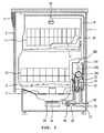
- FIG. 1 is a perspective view of a dishwasher in accordance with an embodiment of the present invention
- FIG. 2 is a longitudinal-sectional view of the dishwasher of FIG. 1 ;
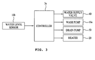
- FIG. 3 is a block diagram illustrating a control system of the dishwasher in accordance with the present invention.
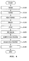
- FIG. 4 is a flow chart illustrating a method of controlling the dishwasher in accordance with the present invention.
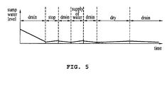
- FIG. 5 is a graph illustrating a variation of the cycle of the dishwasher and a variation of the water level in a sump according to time.
- FIG. 1 is a perspective view of a dishwasher in accordance with an embodiment of the present invention
- FIG. 2 is a longitudinal-sectional view of the dishwasher of FIG. 1
- FIG. 3 is a block diagram illustrating a control system of the dishwasher in accordance with the present invention.
- the dishwasher of the present invention includes a case 1 forming the external appearance of the dishwasher, a door 2 to open and close an opening of the case 1, and a control panel 3 formed at one side of the case 1 and provided with a controller 3 to display and control the operation of the dishwasher.
- the control panel 3 includes a power switch 5 to turn on/off power of the dishwasher, a door handle 4 used to open and close the door 2, a function manipulation unit 7 to allow a user to select the operation of the dishwasher, and a display unit 8 to display the operating state of the dishwasher.
- a washing tub 18 providing a space, in which the dishes are washed, and a sump 16 formed under the washing tub 18 to collect washing water, filter out impurities from the washing water, and re-supply the washing water, from which impurities are filtered out, to the washing tub 18 are provided in the dishwasher.
- Racks to receive dishes are installed in the washing tub 18. Although this embodiment discloses two racks, i.e., an upper rack 11 and a lower rack 12, the racks may be installed in various shapes and numbers according to the size or capacity of the dishwasher.
- spray arms 14 and 15 to respectively spray the washing tub toward the upper rack 11 and the lower rack 12, and a spray arm 24 to spray the washing water from the upper portion to the lower portion of the washing tub 18 are installed in the washing tub 18.
- the sump 16 includes a wash pump 16a (with reference to FIG. 3 ) to pump the washing water stored in the sump 16, and a heater 20 to heat the washing water stored in the sump 16.
- An inflow hole 17 is formed at the lower portion of the washing tub 18, i.e., through the upper surface of the sump 16.
- the washing water including impurities, which was used to wash the dishes, drops down on the lower portion of the washing tub 18, and is collected in the sump 16 through the inflow hole 17.
- the washing water collected in the sump 16 is re-supplied to the spray arms 14, 15, and 24 by the wash pump 16a.
- an air guide 200 to communicate external air and air within the washing tub 18 to each other is additionally formed between the case 1 and the washing tub 18, i.e., on the external surface of the washing tub 18.
- the inside of the washing tub 18 can be maintained in the atmospheric pressure state at any time by the air guide 200, thus preventing the rise of the pressure in the washing tub 18 due to steam or high-temperature air.
- the air guide 200 prevents an injury to a user due to the high pressure in the washing tub 18, in case that the user opens the door 2 by mistake during the operation of the dishwasher under the condition that the pressure in the washing tub 18 is raised.
- the air guide 200 includes an air inlet 201, through which external air is inhaled, an opening 202 communicated with the air in the washing tub 18, and an air channel 203 connecting the air inlet 201 and the opening 202.
- a water supply channel 33 and a drain channel 25, which are separated from the air channel 203, may be formed in the air guide 200. That is, the washing water supplied from a water supply pipe 30 connected to an external water supply source, such as a tap, is supplied to the sump 16 through the water supply channel 33 formed in the air guide 200. The washing water discharged from the sump 16 is discharged to a drain pipe 60 extended to the outside through the drain channel 25 formed in the air guide 200.
- a water supply valve 40 to intermit the washing water supplied to the water supply channel 33 is installed at a designated position of the water supply pipe 30 connecting the water supply channel 33 and the external water supply source.
- the washing water is supplied from the external water supply source to the sump 16 through the water supply channel 33.
- a water level sensor 34 which causes a proper amount of the washing water to flow into the dishwasher to prevent the excessive supply of the washing water, may be additionally installed in the water supply channel 33.
- a drain pump 50 is installed at a designated position of a connection pipe 22 connecting the drain channel 25 and the sump 16.
- a water level sensor 16b may be additionally installed in the sump 16.
- the water level sensor 16b senses the level of the washing water in the sump 16 and whether or not the washing water in the sump 16 is drained, and transmits a signal to a controller 3a, and the controller 3a controls the water supply valve 40, the wash pump 16a, the drain pump 50, and the heater 20.
- the washing water in the sump 16 is discharged to the outside through the drain channel 25 by the drain pump 50.
- the drain channel 25 has a reversed U shape, as shown in FIG. 2 , and passes through a higher position than the level of the washing water in the sump 16.
- washing water newly supplied to the sump 16 may be discharged through the drain channel 25 due to a height difference between the drain channel 25 and the sump 16 and a pressure difference thereby even after the drain pump 50 is stopped.
- washing water is supplied from the external water supply source to the sump 16 through the water supply channel 33 and the washing water in the sump 16 is drained to the outside through the drain channel 25,
- the present invention is not limited thereto. That is, without passing through the air guide, the washing water may be supplied from the external water supply source directly to the sump 16, or the washing water in the sump 16 may be drained directly to the outside.
- the dishwasher of the present invention sequentially or selectively performs preliminary washing, main washing, rinsing, heat-rinsing, and drying cycles to wash the dishes.
- preliminary washing main washing, rinsing, heat-rinsing, and drying cycles to wash the dishes.
- FIG. 4 is a flow chart illustrating a method of controlling a dishwasher in accordance with the present invention
- FIG. 5 is a graph illustrating a variation of the cycle of the dishwasher and a variation of the water level in the sump according to time (herein, the configuration of the dishwasher is the same as that of the dishwasher of FIGs. 1 and 2 ).
- the washing water sprayed from the spray arms 14, 15, and 24 washes the dishes placed on the racks 11 and 12, and then is dropped down and collected in the sump 16 through the inflow hole 17.
- the washing water collected in the sump 16 is re-supplied to the spray arms 14, 15, and 24 through the wash pump 16a.
- the drain pump 50 When the draining of the washing water is started, the drain pump 50 is operated, and the washing water collected in the sump 16 is discharged to the outside through the drain channel 25 and the drain pipe 60.
- the water supply valve 40 When the rinsing of the dishes is started, the water supply valve 40 is opened, and washing water is supplied to the inside of the sump 16 through the water supply pipe 30 and the air guide 200 and is supplied to the spray arms 14, 15, and 24 by the wash pump 16a.
- heat-rinsing of the dishes in which the washing water collected in the sump 16 is heated by the heater 20 and then is supplied to the spray arms 14, 15, and 24, is carried out (operation S120).
- the reason why the heat-rinsing of the dishes is carried out is that the dishes are warmed in advance to enhance the drying efficiency of the dishes.
- the hot washing water used to warm the dishes during the heat-rinsing of the dishes (operation S120), is collected in the sump 16.
- the washing water remains on the washing tub 18 or the dishes is collected again in the sump 16 during the drying of the dishes. Since the heater 20 installed in the sump 16 is used during the drying of the dishes, the washing water collected in the sump 16 is heated by the heater 20 and then is evaporated. Here, steam generated by the evaporation is stuck to the dishes, and thus the drying efficiency of the dishes may be lowered.
- the hot washing water firstly collected in the sump 16 is drained (operation S130).
- the dishes are not directly dried after the draining of the hot washing water, but the stoppage state of all cycles of the dishwasher for treating the dishes is maintained for a designated time.
- cold washing water is supplied again to the sump 16 and is sprayed to the side of the washing tub 18 (operation S160).
- the supplied cold washing water serves to condense hot water and hot air remained in the washing tub 18. Therefore, the supplying of the cold washing water (operation S160) serves to prevent the hot washing water or hot air from being evaporated and stuck to the dishes, and thus prevents the drying efficiency of the dishwasher from being lowered.
- the cold washing water collected in the sump 16 is drained (operation 170), and then the dishes are finally dried (operation 180).
- the drying of the dishes (S180) is completed before the cold washing water collected in the sump 16 during the drying of the dishes by the heater 20 is heated and evaporated, or a drying temperature is controlled to be not more than the boiling point of water, the draining of the cold washing water (S170) after the supply of the cold washing water (S160) may be omitted also.
- the cold washing water requires a longer time than the hot washing water collected in the heat-rinsing of the dishes (S120) to be evaporated, and thus less affects the drying efficiency of the dishes.
- the controller 3a operates the drain pump 50 (operation S130) to drain the hot washing water firstly collected in the sump 16, after the heat-rinsing of the dishes (operation S120).
- the controller 3a operates the drain pump 50 for a designated time, and then stops the operation of the drain pump 50 for a designated time (operation 140). After the designated time has elapsed, the controller 3a operates the drain pump 50 again for a designated time (operation 150). Thereafter, the controller 3a opens the water supply valve 40 such that cold washing water is supplied to the inside of the sump 16 (operation 160).
- the cold washing water supplied to the inside of the sump 16 is sprayed to the inside of the washing tub 18 by the wash pump 16a installed in the sump 16.
- the controller 3a After a designated time from the spraying of the cold washing water to the inside of the washing tub 18 has elapsed, the controller 3a operates the drain pump 50 again to drain the washing water in the sump 16 (operation 170). Thereafter, the controller 3a operates the heater 20 to dry the dishes in the washing tub 18 (operation 180). After the drying of the dishes (operation 180) has been completed, the controller 3a operates the drain pump 50 again to drain the washing water collected in the sump 16 during the drying of the dishes.
- the water level in the sump 16 falls during the draining of the washing water, and then slightly rises due to the supply of the washing water in the washing tub 18 to the inside of the sump 16 during the stopping of the drain, the supplying of the washing water, and the drying of the dishes.
- the method of controlling the dishwasher of the present invention includes stopping all cycles of the dishwasher for a designated time after the draining of the washing water has been completed, and supplying cold washing water, thus preventing the drying efficiency of the dishes from being lowered.
- one of the methods of measuring noise of a dishwasher is to divide the overall noise, generated from the dishwasher during the operation of the dishwasher, by the overall operation time of the dishwasher. Since all the cycles of the dishwasher of the present invention are temporarily stopped, in case that such a noise measuring method is applied to the dishwasher of the present invention, the overall noise is reduced and thus a noise amount is reduced.
Landscapes
- Washing And Drying Of Tableware (AREA)
Applications Claiming Priority (1)
| Application Number | Priority Date | Filing Date | Title |
|---|---|---|---|
| KR1020070106224A KR100939720B1 (ko) | 2007-10-22 | 2007-10-22 | 식기세척기 및 그 제어방법 |
Publications (2)
| Publication Number | Publication Date |
|---|---|
| EP2052662A2 true EP2052662A2 (de) | 2009-04-29 |
| EP2052662A3 EP2052662A3 (de) | 2014-01-22 |
Family
ID=40386516
Family Applications (1)
| Application Number | Title | Priority Date | Filing Date |
|---|---|---|---|
| EP08253427.2A Withdrawn EP2052662A3 (de) | 2007-10-22 | 2008-10-22 | Verfahren zur Steuerung einer Geschirrspülmaschine |
Country Status (4)
| Country | Link |
|---|---|
| US (1) | US20090139547A1 (de) |
| EP (1) | EP2052662A3 (de) |
| KR (1) | KR100939720B1 (de) |
| CN (1) | CN101427902B (de) |
Families Citing this family (3)
| Publication number | Priority date | Publication date | Assignee | Title |
|---|---|---|---|---|
| WO2017018773A1 (ko) * | 2015-07-27 | 2017-02-02 | 엘지전자 주식회사 | 식기세척기 |
| KR102541170B1 (ko) * | 2016-06-10 | 2023-06-08 | 엘지전자 주식회사 | 식기 세척기의 제어방법 |
| US10766157B2 (en) | 2017-02-13 | 2020-09-08 | The Gillette Company Llc | Razor blades |
Family Cites Families (12)
| Publication number | Priority date | Publication date | Assignee | Title |
|---|---|---|---|---|
| US3186418A (en) * | 1963-10-14 | 1965-06-01 | Gen Electric | Apparatus for minimizing spots on articles washed in automatic dishwashers |
| DE2440422A1 (de) * | 1974-08-23 | 1976-03-04 | Euro Hausgeraete Gmbh | Verfahren zum trocknen von geschirr in geschirrspuelmaschinen |
| US4070204A (en) * | 1976-01-22 | 1978-01-24 | General Electric Company | Low-energy dishwasher |
| US4468333A (en) * | 1981-03-25 | 1984-08-28 | Hobart Corporation | Method for a warewasher bypass soil collector |
| IT1268535B1 (it) * | 1993-12-20 | 1997-03-04 | Zanussi Elettrodomestici | Programma operativo per macchina lavastoviglie |
| US5669983A (en) * | 1995-06-08 | 1997-09-23 | Maytag Corporation | Enhanced cycles for an automatic appliance |
| KR100207229B1 (ko) * | 1997-02-24 | 1999-07-15 | 전주범 | 식기세척기의 세척방법 |
| CN1567109A (zh) * | 2003-06-30 | 2005-01-19 | 乐金电子(天津)电器有限公司 | 洗碗机及其控制方法 |
| JP2005058364A (ja) * | 2003-08-08 | 2005-03-10 | Sanyo Electric Co Ltd | 食器洗い機 |
| KR101208280B1 (ko) * | 2005-07-11 | 2012-12-05 | 엘지전자 주식회사 | 식기세척기 및 그 제어방법 |
| KR101268743B1 (ko) * | 2006-03-03 | 2013-05-29 | 엘지전자 주식회사 | 식기세척기의 건조 제어장치 및 방법 |
| KR101268714B1 (ko) * | 2006-04-25 | 2013-05-28 | 엘지전자 주식회사 | 식기 세척기 및 식기 세척기의 제어방법 |
-
2007
- 2007-10-22 KR KR1020070106224A patent/KR100939720B1/ko not_active Expired - Fee Related
-
2008
- 2008-10-21 US US12/254,973 patent/US20090139547A1/en not_active Abandoned
- 2008-10-22 CN CN2008101700602A patent/CN101427902B/zh not_active Expired - Fee Related
- 2008-10-22 EP EP08253427.2A patent/EP2052662A3/de not_active Withdrawn
Also Published As
| Publication number | Publication date |
|---|---|
| CN101427902A (zh) | 2009-05-13 |
| KR20090040734A (ko) | 2009-04-27 |
| KR100939720B1 (ko) | 2010-02-01 |
| EP2052662A3 (de) | 2014-01-22 |
| CN101427902B (zh) | 2011-08-24 |
| US20090139547A1 (en) | 2009-06-04 |
Similar Documents
| Publication | Publication Date | Title |
|---|---|---|
| US10524633B2 (en) | Dishwasher and method of controlling the same | |
| US20090235957A1 (en) | Method for controlling dishwasher | |
| US20080289654A1 (en) | Dish washing machine and control method of the same | |
| EP4050152B1 (de) | Integrierte waschmaschine/trockner und steuerungsverfahren dafür | |
| US9060664B2 (en) | Dishwasher and method of controlling the same | |
| US20070246073A1 (en) | Dishwasher and method of controlling the same | |
| US20080236630A1 (en) | Dish washer and method of controlling the same | |
| KR20090030971A (ko) | 식기세척기 | |
| EP2764815B1 (de) | Geschirrspülmaschine und steuerungsverfahren dafür | |
| EP2772175B1 (de) | Geschirrspülmaschine | |
| US8506721B2 (en) | Dish washer and controlling method thereof | |
| EP2052662A2 (de) | Verfahren zur Steuerung einer Geschirrspülmaschine | |
| US7811386B2 (en) | Method of controlling a dishwashing machine having a steam generator | |
| KR101580125B1 (ko) | 식기세척기의 도어개방방지를 위한 운전방법 | |
| JPH0938602A (ja) | 洗浄機 | |
| KR100798784B1 (ko) | 식기세척기의 제어방법 | |
| KR102547553B1 (ko) | 식기 세척기 및 그 제어방법 | |
| US20100212697A1 (en) | Controlling method of a dishwasher | |
| JP4969408B2 (ja) | 食器洗浄機 | |
| JP3108561B2 (ja) | 食器洗い乾燥機 | |
| KR20220048315A (ko) | 식기 세척기 및 그 제어 방법 | |
| KR20040040303A (ko) | 온풍 발생 장치를 구비한 식기 세척기 | |
| JP2003047583A (ja) | 食器洗い機 | |
| KR20240103091A (ko) | 식기세척기 및 그 제어방법 | |
| KR20080076112A (ko) | 건조장치를 구비한 세탁기의 제어방법 |
Legal Events
| Date | Code | Title | Description |
|---|---|---|---|
| PUAI | Public reference made under article 153(3) epc to a published international application that has entered the european phase |
Free format text: ORIGINAL CODE: 0009012 |
|
| AK | Designated contracting states |
Kind code of ref document: A2 Designated state(s): AT BE BG CH CY CZ DE DK EE ES FI FR GB GR HR HU IE IS IT LI LT LU LV MC MT NL NO PL PT RO SE SI SK TR |
|
| AX | Request for extension of the european patent |
Extension state: AL BA MK RS |
|
| PUAL | Search report despatched |
Free format text: ORIGINAL CODE: 0009013 |
|
| AK | Designated contracting states |
Kind code of ref document: A3 Designated state(s): AT BE BG CH CY CZ DE DK EE ES FI FR GB GR HR HU IE IS IT LI LT LU LV MC MT NL NO PL PT RO SE SI SK TR |
|
| AX | Request for extension of the european patent |
Extension state: AL BA MK RS |
|
| RIC1 | Information provided on ipc code assigned before grant |
Ipc: A47L 15/46 20060101ALI20131216BHEP Ipc: A47L 15/00 20060101AFI20131216BHEP |
|
| 17P | Request for examination filed |
Effective date: 20140331 |
|
| RBV | Designated contracting states (corrected) |
Designated state(s): AT BE BG CH CY CZ DE DK EE ES FI FR GB GR HR HU IE IS IT LI LT LU LV MC MT NL NO PL PT RO SE SI SK TR |
|
| AKX | Designation fees paid |
Designated state(s): DE ES FR GB IT |
|
| 17Q | First examination report despatched |
Effective date: 20150402 |
|
| GRAP | Despatch of communication of intention to grant a patent |
Free format text: ORIGINAL CODE: EPIDOSNIGR1 |
|
| INTG | Intention to grant announced |
Effective date: 20151125 |
|
| STAA | Information on the status of an ep patent application or granted ep patent |
Free format text: STATUS: THE APPLICATION IS DEEMED TO BE WITHDRAWN |
|
| 18D | Application deemed to be withdrawn |
Effective date: 20160406 |