EP2052873A1 - Hängender Aktenordner, Verfahren zur Bildung eines hängenden Aktenordners und Stange - Google Patents
Hängender Aktenordner, Verfahren zur Bildung eines hängenden Aktenordners und Stange Download PDFInfo
- Publication number
- EP2052873A1 EP2052873A1 EP08166326A EP08166326A EP2052873A1 EP 2052873 A1 EP2052873 A1 EP 2052873A1 EP 08166326 A EP08166326 A EP 08166326A EP 08166326 A EP08166326 A EP 08166326A EP 2052873 A1 EP2052873 A1 EP 2052873A1
- Authority
- EP
- European Patent Office
- Prior art keywords
- rod
- hook
- file folder
- hook portions
- pair
- Prior art date
- Legal status (The legal status is an assumption and is not a legal conclusion. Google has not performed a legal analysis and makes no representation as to the accuracy of the status listed.)
- Withdrawn
Links
- 238000000034 method Methods 0.000 title claims description 33
- 239000000463 material Substances 0.000 claims abstract description 16
- 230000007246 mechanism Effects 0.000 claims abstract description 12
- 230000008569 process Effects 0.000 description 13
- 230000003014 reinforcing effect Effects 0.000 description 7
- 238000004519 manufacturing process Methods 0.000 description 6
- 238000004080 punching Methods 0.000 description 6
- 229910000831 Steel Inorganic materials 0.000 description 4
- 239000010959 steel Substances 0.000 description 4
- 239000004677 Nylon Substances 0.000 description 3
- 229910000639 Spring steel Inorganic materials 0.000 description 3
- 229920001903 high density polyethylene Polymers 0.000 description 3
- 239000004700 high-density polyethylene Substances 0.000 description 3
- 238000012986 modification Methods 0.000 description 3
- 230000004048 modification Effects 0.000 description 3
- 229920001778 nylon Polymers 0.000 description 3
- 238000005452 bending Methods 0.000 description 2
- 238000001125 extrusion Methods 0.000 description 2
- 238000001746 injection moulding Methods 0.000 description 2
- 238000003780 insertion Methods 0.000 description 2
- 230000037431 insertion Effects 0.000 description 2
- 239000004033 plastic Substances 0.000 description 2
- 229920003023 plastic Polymers 0.000 description 2
- 239000012858 resilient material Substances 0.000 description 2
- 230000007704 transition Effects 0.000 description 2
- 229910001369 Brass Inorganic materials 0.000 description 1
- 241000270295 Serpentes Species 0.000 description 1
- RTAQQCXQSZGOHL-UHFFFAOYSA-N Titanium Chemical compound [Ti] RTAQQCXQSZGOHL-UHFFFAOYSA-N 0.000 description 1
- 239000000853 adhesive Substances 0.000 description 1
- 230000001070 adhesive effect Effects 0.000 description 1
- 229910052782 aluminium Inorganic materials 0.000 description 1
- XAGFODPZIPBFFR-UHFFFAOYSA-N aluminium Chemical compound [Al] XAGFODPZIPBFFR-UHFFFAOYSA-N 0.000 description 1
- 230000009286 beneficial effect Effects 0.000 description 1
- 239000010951 brass Substances 0.000 description 1
- 230000008859 change Effects 0.000 description 1
- 230000013011 mating Effects 0.000 description 1
- 229910052751 metal Inorganic materials 0.000 description 1
- 239000002184 metal Substances 0.000 description 1
- 238000000465 moulding Methods 0.000 description 1
- 229910052719 titanium Inorganic materials 0.000 description 1
- 239000010936 titanium Substances 0.000 description 1
Images




Classifications
-
- B—PERFORMING OPERATIONS; TRANSPORTING
- B42—BOOKBINDING; ALBUMS; FILES; SPECIAL PRINTED MATTER
- B42F—SHEETS TEMPORARILY ATTACHED TOGETHER; FILING APPLIANCES; FILE CARDS; INDEXING
- B42F15/00—Suspended filing appliances
- B42F15/0011—Suspended filing appliances for sheets, stacks of temporarily bound sheets
- B42F15/0052—Suspended filing appliances for sheets, stacks of temporarily bound sheets for suspending stacks of temporarily bound sheets
- B42F15/0064—Suspended filing appliances for sheets, stacks of temporarily bound sheets for suspending stacks of temporarily bound sheets with movable suspension means
-
- A—HUMAN NECESSITIES
- A47—FURNITURE; DOMESTIC ARTICLES OR APPLIANCES; COFFEE MILLS; SPICE MILLS; SUCTION CLEANERS IN GENERAL
- A47B—TABLES; DESKS; OFFICE FURNITURE; CABINETS; DRAWERS; GENERAL DETAILS OF FURNITURE
- A47B63/00—Cabinets, racks or shelf units, specially adapted for storing books, documents, forms, or the like
-
- B—PERFORMING OPERATIONS; TRANSPORTING
- B42—BOOKBINDING; ALBUMS; FILES; SPECIAL PRINTED MATTER
- B42F—SHEETS TEMPORARILY ATTACHED TOGETHER; FILING APPLIANCES; FILE CARDS; INDEXING
- B42F15/00—Suspended filing appliances
- B42F15/0011—Suspended filing appliances for sheets, stacks of temporarily bound sheets
- B42F15/0017—Suspended filing appliances for sheets, stacks of temporarily bound sheets for filing individual loose sheets
- B42F15/0023—Suspended filing appliances for sheets, stacks of temporarily bound sheets for filing individual loose sheets with single suspension means
- B42F15/0035—Suspended filing appliances for sheets, stacks of temporarily bound sheets for filing individual loose sheets with single suspension means suspended at both extremities
Definitions
- the present invention relates to a hanging file folder, a method of forming a hanging file folder and a rod.
- the present invention is generally related to hanging file folders for mounting to a pair of spaced apart rails. More specifically, the present invention is related to hanging file folders with a structure for permitting adjustment of an effective length of its rod for accommodating variances when adjusting folders along spaced apart rails.
- Hanging file folders for holding papers and documents within a pocket in a filing cabinet with parallel, spaced apart rails are known in the art.
- some hanging file folders tend to have a limited amount of strength and may not provide ease for sliding the folders along the length of rail when holding documents.
- the hooks and rods for hanging the file folder require increased strength in order to provide suitable engagement with the rails of a filing cabinet or the like.
- the hooks and rods must also be designed to resist derailing of the file folder from the rails.
- a file folder may be twisted or flexed and may lock onto the rail.
- file folders with increased strength and better engagement with the rails of a filing cabinet are beneficial.
- FIG. 1 illustrates an overhead view of hanging file folders 4, 6 on a pair of spaced rails 2 in a drawer (not shown), for example.
- the file folder 4 hangs via hooks at points A and B in a perpendicular direction with respect to the rails.
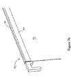
- a file folder may have a "derailing angle" (i.e., the angle at which at least one of the hooks on a rod dislodges from the rail) of less than or equal to 15 degrees with respect to the spaced apart rails 2.
- a "derailing angle" i.e., the angle at which at least one of the hooks on a rod dislodges from the rail
- a hanging file folder for mounting to a pair of spaced apart rails, comprising:
- the at least one of the first and second rods has at least one hook portion thereof moveably mounted to the rod.
- the resilient structure is constructed and arranged between the rod and the moveably mounted hook portion.
- At least one moveably mounted hook portion includes a mounting portion fixed longitudinally to the associated rod.
- the moveably mounted hook portion comprises the resilient mechanism.
- the at least one hook portion comprises the resilient mechanism.
- the resilient mechanism is a tension spring.
- the at least one of the first and second hook portions are removably attached to the first and second rods.
- At least one of the first and second rods has a slot for receiving the hook portions therein.
- the rod has a male portion and the first and second hook portions have a female portion, such that when the hook portions are connected to the opposing ends of the rod, the male portion and female portion mate to secure the hook portions to the rod.
- the first wall, the second wall, or both, of the file folder surrounds the rod.
- the first wall, the second wall, or both, of the file folder is captured by the rod.
- a method of forming a hanging file folder for mounting to a pair of spaced apart rails comprising:
- the method further comprises: forming hook portions with the resilient structure.
- the method further comprises: connecting hook portions to the first and second rods.
- the method further comprises:
- the hook portions are crimped within the channel of the first and second rods.
- the method further comprises:
- the rods are formed by roll forming, stamping, extruding, or punching.
- the hook portions are formed by stamping, punching, injection molding, or extruding.
- a rod for mounting to a pair of spaced apart rails comprising: an elongated body for hanging an object therefrom, the body comprising a first end and a second end; a pair of hook portions on opposing ends of the rod for engaging the pair of spaced apart rails; and a resilient structure for permitting at least one of the pair of hook portions to move longitudinally with respect to the elongated body, wherein an effective length of the body is adjusted to accommodate variances in the angle at which the rod is mounted on the rails and to maintain engagement therewith.
- the object comprises a first wall of a file folder body, the file folder body comprising the first wall and a second wall to form a pocket for holding materials therein, and wherein the second wall hangs from a second rod such that when the rod and second rod are hung on the spaced apart rails, the pocket is suspended between the rod and second rod.
- the first wall of the file folder surrounds the elongated body of the rod.
- the first wall of the file folder is captured in the elongated body of the rod.
- At least one hook portion is moveably mounted to the elongated body.
- the resilient structure is constructed and arranged between the elongated body and the moveably mounted hook portion.
- the moveably mounted hook portion includes a mounting portion fixed longitudinally to the elongated body.
- the moveably mounted hook portion comprises the resilient mechanism.
- At least one hook portion comprises the resilient mechanism.
- the resilient mechanism is a tension spring.
- the hook portions are removably attached to the elongated body.
- the rod has a slot for receiving the hook portions therein.
- the rod has a male portion and the hook portions have female portions, such that when the hook portions are connected to the first and second ends of the rod, the male portion and female portion mate to secure the hook portions to the elongated body of the rod.
- the hanging file folder includes a first rod with a pair of hook portions on opposing ends thereof for engaging the pair of spaced apart rails; a second rod with a pair of hook portions on opposing ends thereof for engaging the pair of spaced apart rails; and a file folder body with first and second walls forming a pocket for holding materials therein.
- the first wall of the file folder body is connected to the first rod, and the second wall of the file folder body is connected to the second rod, such that the pocket is suspended between the first and second rods.
- At least one of the first and second rods has a resilient structure for permitting at least one of the hook portions thereof to move longitudinally and adjust an effective length of its rod for accommodating variances in the angle at which folders are mounted on the rails and maintaining engagement therewith.
- An aspect of the invention provides a method of forming a hanging file folder for mounting to a pair of spaced apart rails.
- the method includes forming a first rod with a pair of hook portions on opposing ends thereof; forming a second rod with a pair of hook portions on opposing ends thereof; attaching a first wall of a file folder body to the first rod; and attaching a second wall of the file folder body to the second rod.
- At least one of the rods includes a resilient structure for permitting at least one of the hook portions thereof to move longitudinally and adjust an effective length of its rod for accommodating variances in the angle at which the folders are mounted on the rails to maintain engagement therewith.
- the rod for mounting to a pair of spaced apart rails.
- the rod includes an elongated body for hanging an object therefrom.
- the body has a first end and a second end.
- a pair of hook portions are provided on opposing ends of the rod for engaging the pair of spaced apart rails, and a resilient structure is provided to permit at least one of the pair of hook portions to move longitudinally with respect to the elongated body.
- An effective length of the body is adjusted to accommodate variances in the angle at which the rod is mounted on the rails and to maintain engagement therewith.
- the object is a magazine or newspaper.
- file folders may be laterally or perpendicularly hung on spaced apart rails provided within a drawer of a filing cabinet.
- file folders may be mounted on spaced apart rails running generally parallel with the length of the drawer or on spaced apart rails that may run parallel to the width of the drawer.
- any type of rail system may be used.
- a rail 102 with a reinforcing rib 104 may be used in a drawer (not shown) of a filing cabinet.
- the reinforcing rib 104 provides strength to the rail 102 so as to prevent bending of the body of the rail.
- the reinforcing rib 104 may be formed uniformly as a single unit with the rail 102. As shown, the reinforcing rib 104 may be provided a distance D from the top 106 or contact point of a rail 102 to the top 108 of the reinforcing rib 104.
- Figure 10 illustrates an embodiment wherein a channel 110 comprising a rail 112 may be used for hanging file folders.
- the channel 110 is shaped such that at least one extended rail 112 with a top 114 or contact surface is formed for receiving a hook of a rod of a file folder to hang thereon.
- the channel 110 comprises a first attachment end 116 and a second attachment end (not shown) such that channel 110 may be mounted perpendicularly on the spaced apart rails (only one rail 102 of which is shown) of a file drawer. By attaching the ends of the channel 110 to the spaced apart rails in a drawer, file folders may be hung or mounted in an opposite or perpendicular direction (e.g., than originally intended).
- Figure 2 illustrates a hanging file folder 10 for mounting to a pair of spaced apart rails 8 in a drawer of a filing cabinet, for example.
- file folder 10 has a body 11 comprising a first wall 12 and second wall 14 that forms a pocket 16 for holding materials therein.
- the pocket 16 of the file folder 10 is designed to hold papers, documents and the like of various shapes and sizes, for example.
- the first wall 12 of the body 11 is connected to a first rod 18 and the second wall 14 of the body 11 is connected to a second rod 20.
- a bottom end of first wall 12 is connected to a bottom end of the second wall 14 of the body 11 of the file folder 10 at 13, thus forming a pocket 16 therebetween.
- the pocket 16 of the folder 10 is designed such that it is suspended between the first and second rods 18, 20.
- the folder 10 may be connected to the rods 18, 20 in any number of ways.
- an open end 22 of the first wall 12 and an open end 24 of the second wall 14 may be designed such that they surround the first rod 18 and second rod 20, respectively (e.g., as shown in Figure 2 ).
- the ends 22, 24 may comprise rod pockets designed to receive the rods 18, 20, for example.
- the rods 18, 20 may be designed such that the ends 22, 24 of the first wall 12 and second wall 14 are captured within or connected to the rods 18, 20 (e.g., as further described with reference to Figure 5c).
- the method of connecting the rods 18, 20 to the body 11 of the file folder 10 may be performed in any manner and therefore should not be limited to those as described herein.
- Figure 2 also shows the first rod 18 and second rod 20 with a pair of hook portions 26 and 28, respectively, on opposing ends thereof.
- the hook portions 26, 28 are provided to engage a pair of spaced apart rails 8 in a filing cabinet or the like.
- at least one of the first and second rods 18, 20 comprises a resilient structure for permitting at least one of the hook portions 26, 28 thereof to move longitudinally, thus adjusting an effective length of the rod body 18, 20.
- the effective length of the rod body 18, 20 is adjusted to prevent the possibility of dislodging or coming off of the rail 8 when moving the file folder along the rail 8 (e.g., such as when opening the walls 12, 14 of the body 11 of the file folder 10 to access contents in the pocket 16 therein, or when moving a file folder 10 to access an additional folder).
- the use of the resilient structure with the rod and hook portions as will be further described, thereby accommodates variances in the angle at which the folders are mounted on the rails, for example, and maintains engagement of the rod and hook portions with the rails. Additional features and advantages will become further evident below.
- FIG 3 illustrates a detailed view of the end 22 of first wall 12 of the hanging file folder 10 of Figure 2 with a hook and rod assembly 30 in accordance with an embodiment of the present invention.
- the hook and rod assembly 30 is surrounded by end 22 (or provided through the rod pocket 22) of the first wall 12 of the file folder 10.
- the end 22 of first wall 12 is herein described for illustrative purposes only and should not be limiting, i.e., the hook and rod assembly 30 may be used with first wall 12, second wall 14, or both.
- the hook and rod assembly 30 as herein described may be used on one or both opposing ends of the first and/or second rods 12, 14.
- at least one hook of the pair of hook portions 26 and/or 28 may comprise a hook and rod assembly 30.
- the hook and rod assembly 30 comprises a hook portion 32 and a rod portion 62.
- hook and rod assembly 30 may be formed as a single unit.
- at least one of the first and second hook portions 32 of the assembly 30 may be removably attached to the first and second rods 18, 20 or rod portions 62.
- Figure 4a illustrates an example of the removably attached hook portion 32 of Figure 3 in further detail.
- the hook portion 32 may be moveably mounted with respect to rod portion 62.
- Hook portion 32 comprises a proximal end 36 and a distal end 38.
- Proximal end 36 comprises a hook 39 for surrounding a rail 8 (as shown in Figure 2 ).
- hook 39 comprises an elongated portion 40 and a longitudinal portion 42.
- Elongated portion 40 of hook 39 also comprises an end portion 46.
- elongated portion 40 may comprise a bulbous end portion 46, as shown in Figure 4a .
- bulbous portion 46 may be provided near the end of the hook 39 in order to aid in keeping the hook portion 32 of the hook and rod assembly 30 on a rail.
- the elongated portion 40 transitions into the longitudinal portion 42 via a curved or radiused portion 48.
- the curved portion 48 is provided along the underside of the longitudinal portion 42 of the hook portion 32.
- the curved portion 48 is formed such that it comes into contact with a rail for hanging the file folder 10.
- the curved portion 48 comprises a variable radius for preventing excessive contact with the rail.
- Longitudinal portion 42 extends into a hook body 44.
- the end of longitudinal portion 42 transitions into hook body 44 and includes an extension portion 50 and an abutment portion 54.
- Extension portion 50 is formed such that it comes into contact with an opposite (i.e., inner) side of a rail when hanging file folder 10.
- extension portion 50 may comprise a rounded surface or variable radius for preventing excessive contact with the rail.
- Abutment portion 54 is provided such that it sits adjacently against an edge of the rod portion 62 when assembled (as will be described with reference to Figure 4c ).
- the hook body 44 may also comprise a limiting portion 52.
- the limiting portion 52 is provided as a stop for limiting the amount of longitudinal movement of the hook portion 32 with respect to rod portion 62.
- the area 51 between the extension portion 50 and limiting portion 52 provides a bearing surface for the hook portion 32 to move or slide on a part of the rod, as will be discussed in greater detail below.
- limiting portion 52 limits the length the bearing surface 51 may move with respect to the rod 62.
- first and second rods may have at least one hook portions thereof moveably mounted to the rod portion 62.
- the resilient structure is constructed and arranged between the rod 62 and the hook 39 near the distal end 38 of hook portion 32.
- the hook body 44 of hook portion 32 comprises a resilient structure 58 as shown in Figure 4a .
- resilient structure 58 comprises a tension spring.
- the resilient structure 58 or spring may comprise a rounded shape, much like the Greek letter Omega, with first and second legs 56 joined at 60.
- resilient structure may comprise a "U"-shape, "V"-shape, "W”-shape, or any other known shapes for providing resiliency where angular deflection of at least one member may occur.
- Figures 11a-11c illustrate examples of alternate designs for a resilient mechanism that may be used with a hook and rod assembly in accordance with an embodiment.
- Figure 11a illustrates an example of a resilient structure comprising a "V"-shape.
- Figure 11b illustrates an example of resilient structure comprising a "snake”-like shape comprising a plurality of curves.
- Figure 11c illustrates an example of a resilient structure comprising an "S"-shape.
- the resilient structure 58 may also comprise a member made from a resilient material permitting elongation thereof.
- the resilient structure 58 may be formed integrally as one continuous piece with the hook portion 32.
- the hook portion 32 is formed through a stamping, punching, or molding process.
- hook portion 32 may be formed of nylon.
- the hook portion 32 may be of any known length.
- the elongated portion 40 of the hook 39 of hook portion 32 may be designed to extend below the height of a rail, for example.
- the length (e.g., length L of the elongated portion 40 from the top of longitudinal portion 42 to the end portion 46 along Y-axis, as indicated in Figure 4a ) of the hook portions 32 may comprise a length L designed to accommodate the distance D from the top 106 of a rail 102 in a file cabinet to the top 108 of a reinforcing rib 104 of the rail 102, as shown in Figures 9a and 9b .
- the length L and width W (e.g., length of longitudinal portion 42 from the abutment portion 54 to the elongated portion 40 along the X-axis, as indicated in Figure 4a ) of the hook portion 32 may be defined by a window comprising the distance from a rail to the inside of a file cabinet.
- the window may comprise approximately 9.6 millimeters (mm) by approximately 11.5 millimeters (mm).
- hook portion 32 may comprise a depth or thickness T of 2 millimeters (mm) and a length L of 9.6 millimeters (mm).
- the hook portion 32 may comprise a thickness T to minimize the impact of the drawer space used by the file folder 10. That is, the thickness T may be adjusted such that a drawer may hold more file folders based on the depth or thickness of the hook. For example, a drawer may be designed to hold eighty (80) file folders. However, by adjusting the depth or thickness T of the hook in the Z-direction (i.e., along Z-axis, as indicated in Figure 4a ), the same drawer may hold one hundred (100) file folders.
- the distance of the bearing surface 51 is set to limit the extension of the resilient structure 58.
- the distance of the bearing surface 51 may be determined by a distance needed to extend the file folder.
- the distance of the bearing surface 51 may also be determined by the amount of flexure or "flex" that would cause the resilient structure 58 to permanently yield (i.e. experience plastic deformation).
- the amount of flex may be determined or affected by the material used to form resilient structure 58.
- a material such as nylon may bend more than a high density polyethylene (HDPE) before yielding.
- resilient structure 58 may comprise the material of which the hook portion 32 comprises.
- the resilient structure 58 may comprise nylon or HDPE, for example.
- the resilient structure 58 may comprise a spring steel.
- the distal end 38 of hook portion 32 may also comprise an attachment feature such as a mounting portion 56.
- Figure 4a illustrates a mounting portion 56 on the distal end 38 of the hook body 44.
- the mounting portion 56 is designed to mount or hold the hook portion 32 within the rod portion 62.
- mounting portion 26 of hook portion 32 may comprise a female portion and rod 62 may comprise a male portion, wherein when the hook portion(s) 32 are connected to the opposing ends of the rod 62, the male and female portions mate to secure the hook portion(s) 32 to the rod 62.
- the mounting portion 56 may comprise a hole or opening for receiving an extended portion or pin located on the rod portion 62, for example, as shown in the Figures.
- the mounting portion 56 assists in keeping the hook portion 32 within the rod portion 62 and may also assist in limiting the amount of movement of the hook portion 32 with respect to the rod portion 62.
- Figure 4b illustrates the rod portion 62 in accordance with an embodiment of the present invention.
- Figure 4b illustrates a proximal end 64 of the rod 62 and elongated body 66.
- the elongated body 66 of rod 62 may comprise a channel or a slot 68 for receiving hook portions 32 therein.
- the channel or slot 68 may comprise a "U"-shape at the proximal end 64 of the rod 66, but should not be limited to such.
- the body 66 of rod 62 may be roll formed, for example.
- the proximal end 64 of the body 66 comprises a channel 68 and a receiving portion 65.
- receiving portion 65 may be a section that is substantially flat.
- Rod 62 is designed to receive movably mounted hook portion 32 within its slot 68 and receiving portion 65, for example.
- Rod 62 comprises an end 70 for abutment with the abutment portion 54 of the hook portion 32.
- Rod 62 also comprises an end 71 for abutment with the distal end 38 of the hook portion 32.
- the rod 62 may also comprise attachment features such as a rounded edge 72 and a male portion or extended mounting portion or pin 73.
- Limiting edge 72 and mounting portion 73 may be provided near the proximal end 64 of the rod 62, for example.
- Limiting edge 72 is designed to cooperate with the extension portion 50, bearing surface 51, and limiting portion 52 of the hook portion 32.
- the limiting edge 72 also provides an area for the bearing surface 51 to slide thereon along the rod 62, as shown in Figure 4c .
- the extended mounting portion or pin 73 may be formed with receiving portion 65 or in elongated body 66, for example.
- the extended mounting portion or pin 73 within the body 66 may be designed to cooperate with the female mounting portion or opening 56 of the hook portion 32.
- the opening 56 of the hook portion(s) 32 mate with the male, extended mounting portions 73 of the rod 62 to secure the hook portions 32 to the rod 62.
- the extended mounting portion or pin 73 may comprise any number of shapes or designs designed to correspond with the shape of the mounting portion 56 of the hook 32.
- Figure 4c illustrates the final hook and rod assembly 30 of the hook portion 32 and rod 62 of Figures 4a-4b for use with the hanging file folder 10 of Figure 2 .
- the manufacturing assembly process is further described with respect to Figures 8a-8d below.
- the hook portion 32 is mounted within the roll formed body 66 of the rod 62.
- the attachment features of the hook 32 e.g., abutment portion 54 and mounting portion 56
- of the rod 62 e.g., end 70, limiting edge 72, receiving portion 65, edge 71, and the mounting portion 73
- the attachment and insertion of the hook portion 32 into the rod 62 allows for adjustment of the effective length of the rod by permitting the hook portion 32 to move longitudinally with respect to the rod 62.
- the resilient structure 58 allows for the hook portion 32 to spring back into the rod body 66 when removed from a rail of a file drawer, for example.
- the limiting portion 52 and limiting edge 72 limit the amount or length of extension of the hook portion 32.
- Figures 5a and 5b illustrate an extension 80 that may be added to the assembly of Figure 4c in accordance with an embodiment of the present invention.
- extension 80 may comprise a separate piece (not shown) to be added to the elongated body 66 of the rod portion 62, or may be formed with elongated body 66 uniformly (as shown in Figures 5a and 5b ).
- the extension 80 may be designed to cover part of the hook portion 32 to enhance the appearance of the length of the rod 62, for example.
- the extension 80 may be formed to sit over longitudinal portion 42 of the hook portion 32.
- the extension 80 may also enhance the strength of the hook portions 32.
- Figures 6a and 6b illustrate a front and back view of the extension 80 in use with a hanging file folder 10 in accordance with an embodiment of the present invention. As shown, the extension 80 may be visible outside of the body 11 of the file folder.
- Figures 7a and 7b illustrate an alternate rod 82 for use with the hook portion(s) 32 of Figure 3 in accordance with an embodiment of the present invention.
- Rod 82 is designed such that a channel 84 formed within the elongated body 83 that may capture a first or second wall 12, 14 of the body 11 of the file folder 10.
- the first wall 12 may be inserted into a slot 88 formed by the receiving portion 85 and extension wall 87 formed in elongated body 83.
- a limiting portion 72 such as shown in Figure 4a , may be formed with an edge 86 thereon for assisting in holding a wall 12, 14 of the folder 10.
- the wall 12 may be crimped in the slot 88 between the receiving portion 85, edge 86, and wall 87 of the elongate body 83 of the rod 82 as shown in Figure 7b .
- the rod 62 may be formed from 0.4 millimeter (mm) steel material.
- the rod may be formed from metal.
- the rod may be formed from steel, brass, aluminum, or titanium.
- the rod may be formed using a roll forming, stamping, extruding and/or punching, or other known manufacturing processes.
- hook portion 32 may be formed from a resilient material.
- the rod and/or hook portion may be formed from plastic.
- the parts of the assembly 30 may be formed via extrusion process.
- the assembly process may be performed on a conveyor system, for example.
- the rod portion 62 and its features e.g., channel 68, limiting portion 72
- the hook portions 32 may be formed by stamping, punching, injection molding, or extrusion processes, for example.
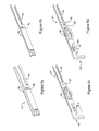
- Figures 8a-8d illustrate a method of manufacturing and assembly for a hook portion 32 and a rod 62 of a hook and rod assembly such as shown in Figures 3-7b in accordance with an embodiment of the present invention.
- the assembly process is designed based on speed. For example, due to high volumes, assembly of the features may meet or exceed rates of 200 parts per minute.
- the hook portions 32 are sorted and positioned individually in a hopper or fixture 92.
- the fixture 92 is designed to hold a plurality of hook portions 32 until the rod is in place for assembly.
- the manufacturing and assembly of the hook and rod assembly 30 may comprise the following steps: the rod is formed in the form of a substantially flat piece of material, as shown in Figure 8a , through a stamping process, for example.
- the body of the rod 66, including the mounting portion shown as element 94, is substantially flat. At least a top edge 90 and bottom edge 92 are then roll formed to form the structure as shown in Figure 8b .
- the rod 62 may be aligned with a fixture comprising a plurality of hook portions 32.
- the hook portions 32 may be aligned and positioned within the body 66 of the rod 62 as shown in Figure 8c .
- actuators (not shown) may be used to push a single hook portion 32 out of the fixture 92 and into the body 66 of the rod 62, as indicated by an arrow.
- the rod 62 may then be deflected, stamped, or otherwise formed 98 around the hook portion 32 so as to form attachment features for maintaining the hook portion 32 and rod 62 in a mating relationship.
- the attachment features i.e., limiting edge 72, mounting portion 73
- the attachment features may be formed from flat portions 96, 94, respectively, during the assembly as shown by Figures 8c-8d .
- the attachment features may be stamped to hold the hook portion 32 therein and thus complete the hook and rod as shown in Figure 8d .
- the method of attaching the hook portion to the rod may be automated.
- mounting portions such as a male portion (e.g., pin 73) or female portion (e.g., mounting portion 56) may be formed on the hook portion and/or rod during the manufacturing/assembly process.
- adhesive may be used to assist in fixing the hook portion and rod components together as well.
- the above described manufacturing and assembly method enables one to fasten or secure the hook portion 32 in the assembly 30 in one motion, thus aiding in the assembly time needed to run this process at a high rate.
- the above noted materials and processes are merely exemplary and should not be limiting, and the rod and hook portions may be assembled using any number of materials and/or processes.
- hook and rod assembly 30 may be formed as a single unit.
- hook and rod assembly 30 may be formed from materials (e.g., such as steel and/or spring steel) that allow for a single or uniform body.
- the hook portion 32 may be attached to the rod 62 using known processes for unifying the assembly 30.
- the hook portion 32 may be formed of spring steel which is attached to a rod 62 of steel.
- the hook and rod assembly 30 may be used alone for mounting to a pair of spaced apart rails. That is, hook and rod assembly 30 need not be used in pairs, as shown with a file folder 10. For example, when hanging a magazine, newspaper, or other object, only one rail may be needed.
- the hook and rod assembly 30 may comprise a single rod with a pair of hooks portions, as described above, for hanging on spaced apart rails.
- the hook and rod assembly 30 as herein described improves the quality of a file folder.
- the assembly 30 provides greater strength for holding documents and file therein on rails in a filing cabinet.
- the roll-forming of the rod portion 62 increases the amount of weight that may be held by the file folder 10.
- the rod portion 62 also resists bending and twisting and thus resists deforming and buckling of the rod 62 under a load.
- the extension portion 80 also increases the strength of the overall assembly.
- the assembly 30 provides better engagement with rails 8 by providing minimal contact with the rail 8.
- the file folder 10 or hook and rod assembly 30 may easily move with respect to the rail, such as when twisted with respect to the rails.
- the assembly is also designed to resist derailing or binding of the file folder.
- the file folder 10 or assembly 30 may be twisted to a maximum gripping angle while in contact with the rail. Additionally, the assembly 30 also increases the ease of sliding the hook and rod assembly 30 of the file folder along the length of a rail.
- the assembly 30 may be pushed at an angle with respect to the rails, thereby creating a greater distance or span between the hooks of the rod during adjustment and sit between the rails.
- the design of the hook and rod assembly 30 increases the derailing angle at which at least one of the hooks on a rod dislodges from the rail. More specifically, the derailing angle of the hook and rod assembly 30 may be increased to at least 29 degrees.
- the assembly 30 also allows for one to hang a file folder 10, magazine, or other object along spaced apart rails within cabinets which may not be provided at the same distance, such as along rails within a filing cabinet that may not be parallel or that may not be spaced the same distance from one another in one drawer or cabinet.
Landscapes
- Sheet Holders (AREA)
- Supports Or Holders For Household Use (AREA)
- Mirrors, Picture Frames, Photograph Stands, And Related Fastening Devices (AREA)
- Drawers Of Furniture (AREA)
Applications Claiming Priority (1)
| Application Number | Priority Date | Filing Date | Title |
|---|---|---|---|
| US11/877,045 US9573408B2 (en) | 2007-10-23 | 2007-10-23 | Resilient rod feature in hanging file folder |
Publications (1)
| Publication Number | Publication Date |
|---|---|
| EP2052873A1 true EP2052873A1 (de) | 2009-04-29 |
Family
ID=40343535
Family Applications (1)
| Application Number | Title | Priority Date | Filing Date |
|---|---|---|---|
| EP08166326A Withdrawn EP2052873A1 (de) | 2007-10-23 | 2008-10-10 | Hängender Aktenordner, Verfahren zur Bildung eines hängenden Aktenordners und Stange |
Country Status (3)
| Country | Link |
|---|---|
| US (8) | US9573408B2 (de) |
| EP (1) | EP2052873A1 (de) |
| CN (1) | CN101417569A (de) |
Cited By (3)
| Publication number | Priority date | Publication date | Assignee | Title |
|---|---|---|---|---|
| EP2303601A4 (de) * | 2009-05-26 | 2012-01-04 | World Wide Stationery Mfg Co | Stange für einen hängeaktenordner |
| USD689548S1 (en) | 2011-03-25 | 2013-09-10 | Ideastream Consumer Products, Llc | Folder |
| USD691195S1 (en) | 2011-03-25 | 2013-10-08 | Ideastream Consumer Products, Llc | Folder |
Families Citing this family (8)
| Publication number | Priority date | Publication date | Assignee | Title |
|---|---|---|---|---|
| US9573408B2 (en) | 2007-10-23 | 2017-02-21 | Lsc Communications Us, Llc | Resilient rod feature in hanging file folder |
| CN102963156A (zh) * | 2012-11-28 | 2013-03-13 | 毛若然 | 一种方便分类的试卷袋 |
| US9676223B2 (en) * | 2015-09-17 | 2017-06-13 | Microdata Corporation | Secure document receptacle |
| US10099504B2 (en) * | 2015-12-23 | 2018-10-16 | Lsc Communications Us, Llc | File folder hanging rods and related methods |
| CN107984926B (zh) * | 2017-12-05 | 2019-09-03 | 佛山市鑫锦龙机械科技有限公司 | 一种挂快劳文件夹生产流水线 |
| US10435237B1 (en) * | 2018-01-23 | 2019-10-08 | Deborah Schmeck | Garbage bag sling |
| US20230087386A1 (en) * | 2020-08-26 | 2023-03-23 | Simple Living Solutions, LLC | System and method for a support clip to attach a decorative element |
| CN112158462A (zh) * | 2020-10-26 | 2021-01-01 | 上海古鳌电子科技股份有限公司 | 一种物品存储袋及使用方法 |
Citations (3)
| Publication number | Priority date | Publication date | Assignee | Title |
|---|---|---|---|---|
| FR2411092A1 (fr) | 1977-12-08 | 1979-07-06 | Saurou Michel | Barrette de suspension pour dossiers ou classeurs suspendus |
| EP1535752A2 (de) | 2003-11-26 | 2005-06-01 | Esselte Leitz GmbH & Co. KG | Hängebehälter |
| EP1607236A1 (de) | 2004-06-14 | 2005-12-21 | Wei-Kang Yeh | Ordner für Hängemappe |
Family Cites Families (136)
| Publication number | Priority date | Publication date | Assignee | Title |
|---|---|---|---|---|
| US546647A (en) * | 1895-09-24 | Apparatus for holding drawings | ||
| US1348546A (en) * | 1920-08-03 | Gaud-suspending device | ||
| US2656233A (en) * | 1953-10-20 | Device foe delivering cards | ||
| US1268143A (en) * | 1917-05-31 | 1918-06-04 | Carl A Palmgren | Filing device. |
| US1524348A (en) * | 1921-06-08 | 1925-01-27 | James H Field | Filing device |
| US1867159A (en) * | 1931-02-11 | 1932-07-12 | Acco Products Inc | Filing device |
| US1867158A (en) * | 1931-02-11 | 1932-07-12 | Acco Products Inc | Filing device |
| US1953552A (en) * | 1932-05-31 | 1934-04-03 | Mce Dequeker & Cie Soc | Apparatus for the vertical filing of file wrappers or similar objects |
| US2257052A (en) * | 1941-04-05 | 1941-09-23 | Atto N Hanna | Filing device |
| US2325317A (en) * | 1941-09-09 | 1943-07-27 | Atto N Hanns | Filing device |
| US2605769A (en) * | 1942-10-08 | 1952-08-05 | Lampel Bela | Appliance for the upright filing of index cards |
| US2631589A (en) * | 1944-10-17 | 1953-03-17 | Zalkind Philip | Reinforced folder |
| US2524743A (en) * | 1947-04-12 | 1950-10-03 | Frederick M Wright | Garment hanger support |
| US2519996A (en) * | 1948-02-09 | 1950-08-22 | Blake Ralph | Adjustable curtain rod |
| US2626610A (en) * | 1948-11-01 | 1953-01-27 | Specialty Mfg Company Ltd Off | Vertical-type file folder |
| US2608420A (en) * | 1949-01-03 | 1952-08-26 | Frank T Eck | Load bracing structure for vehicles |
| US2765793A (en) * | 1952-12-24 | 1956-10-09 | Becker Otto Alfred | Filing drawings |
| US2874699A (en) * | 1953-02-13 | 1959-02-24 | Dunleavy James Frank | Filing folders |
| US2707610A (en) * | 1954-02-12 | 1955-05-03 | Waugh Equipment Co | Damped resilient hook device |
| US2910985A (en) * | 1957-03-12 | 1959-11-03 | Gladys K Epstein | Index tab |
| US2983232A (en) * | 1959-12-15 | 1961-05-09 | Pacific Car & Foundry Co | Cargo braces |
| FR1330836A (fr) * | 1962-05-16 | 1963-06-28 | Perfectionnements aux dossiers suspendus | |
| US3244179A (en) * | 1963-09-23 | 1966-04-05 | Gary Ind Inc | File folder assembly |
| GB1039557A (en) * | 1964-07-31 | 1966-08-17 | Roneo Ltd | Improvements in or relating to filing systems |
| US3410512A (en) * | 1966-10-20 | 1968-11-12 | Vecchio Michael Del | Crib attachment |
| US3424418A (en) * | 1967-02-14 | 1969-01-28 | Ford Motor Co | Automatically retractable coat hook |
| US3524688A (en) * | 1968-03-14 | 1970-08-18 | Jesse W Dean | File suspension means |
| US3501019A (en) * | 1968-07-11 | 1970-03-17 | Armstrong Store Fixture Corp | Means for binning and banding display shelves |
| US3572867A (en) * | 1969-02-27 | 1971-03-30 | Gary Ind Inc | Hanger hook assembly for suspension file folders |
| FR2040760A5 (de) * | 1969-04-11 | 1971-01-22 | Organisation Economique | |
| US3667854A (en) * | 1970-08-31 | 1972-06-06 | Oxford Pendaflex Corp | Binder for a suspension file |
| US3684340A (en) * | 1970-11-27 | 1972-08-15 | Nat Bank Book Co Inc | Hanger file device |
| US3863828A (en) * | 1971-06-18 | 1975-02-04 | Shaw Walker Co | Self laminated hanging file folder |
| US3779393A (en) * | 1971-08-11 | 1973-12-18 | C Grundell | File for documents and the like |
| US3790242A (en) * | 1972-01-24 | 1974-02-05 | Mead Corp | Binder carrier and support structure |
| BE795215A (fr) * | 1972-02-17 | 1973-05-29 | Fridlund Gosta | Classeur de bureau |
| US3850488A (en) * | 1972-03-27 | 1974-11-26 | A Elias | Means for filing documents |
| US3801175A (en) * | 1972-09-21 | 1974-04-02 | J Giulie | Hanger and binder unit |
| GB1448016A (en) * | 1972-09-25 | 1976-09-02 | Grundell Carl E | File for documents |
| US3865445A (en) * | 1973-02-26 | 1975-02-11 | Wright Barry Corp | Hanging binder |
| US3957321A (en) * | 1974-09-23 | 1976-05-18 | Acco International Inc. | Suspension file folder |
| FR2266606B1 (de) * | 1974-10-21 | 1978-05-05 | Malsert Expl Sa Henri | |
| US4105268A (en) * | 1975-10-08 | 1978-08-08 | Elias Abram G | Document hanging system |
| US4056296A (en) | 1976-03-17 | 1977-11-01 | Wright Line Inc. | Document holder |
| US3999630A (en) * | 1976-03-26 | 1976-12-28 | Mcphee Donald T | Transport and serving device |
| IL51101A (en) * | 1976-04-05 | 1979-07-25 | Superfile Ltd | Suspension files |
| US4053057A (en) * | 1976-05-03 | 1977-10-11 | Oxford Pendaflex Canada Limited | Suspended filing folders |
| DE2717318A1 (de) * | 1977-04-19 | 1978-10-26 | Zippel Gmbh & Co Kg Herbert | Kennzeichentraeger |
| US4103606A (en) * | 1977-04-22 | 1978-08-01 | Mr. Drumstick, Inc. | Cooking device |
| DE2847537A1 (de) * | 1977-11-03 | 1979-05-10 | Christopher Edward Terrell | Hakenklammer |
| DE2751683C3 (de) * | 1977-11-18 | 1981-04-09 | Brügmann, Dirk Alexander, 5840 Schwerte | Sicht- bzw. Griffreiter aus Kunststoff zur Anbringung an der oberen Randkante von Hängeheftern oder Hängetaschen |
| US4181381A (en) * | 1978-04-14 | 1980-01-01 | National Blank Book Company, Inc. | Filing device |
| CA1091120A (en) | 1978-04-26 | 1980-12-09 | David C. Moore | Glide insert for hanging file folder system |
| US4256425A (en) * | 1979-03-12 | 1981-03-17 | Equipment Manufacturing, Inc. | Latch assembly for dunnage bars |
| US4285555A (en) * | 1979-12-10 | 1981-08-25 | Wright Line Inc. | Document holder |
| US4420086A (en) * | 1980-12-16 | 1983-12-13 | Bardes Products, Inc. | Filing hanger |
| GB2094232B (en) * | 1981-01-13 | 1985-06-19 | Mc2 Ltd | Suspension filing hooks and retainers therefor |
| US4445799A (en) * | 1981-02-12 | 1984-05-01 | Wright Line Inc. | Document holders |
| CA1138385A (en) * | 1981-02-16 | 1982-12-28 | Charles W. Bishop | Clothes rack |
| US4527694A (en) * | 1982-05-27 | 1985-07-09 | Bolt William S | Suspendable hanger framework assembly |
| US4870767A (en) * | 1983-01-27 | 1989-10-03 | Davies Alan F | Visible file pockets |
| USD285217S (en) * | 1983-08-01 | 1986-08-19 | Analytical Products, Inc. | Suspendable bag |
| US4530176A (en) * | 1983-09-27 | 1985-07-23 | Berkey Photo, Inc. | Apparatus for cataloguing photographs and negatives |
| IT1195512B (it) * | 1983-10-19 | 1988-10-19 | Ezio Bertesi | Dispositivo a raccoglitore per tubolati e documenti,ad elementi componibili |
| AT388652B (de) * | 1985-04-25 | 1989-08-10 | Blum Gmbh Julius | Schublade mit unterteilung |
| JPH0324997Y2 (de) | 1985-09-12 | 1991-05-30 | ||
| US4666047A (en) * | 1985-12-16 | 1987-05-19 | Plan Hold Canada Inc. | Hanger support for filing cabinets |
| US4842435A (en) * | 1988-02-08 | 1989-06-27 | Tab Products Company | Adjustable document handle |
| USD322284S (en) | 1988-04-15 | 1991-12-10 | Carter-Parratt Limited | Suspension file |
| US4950096A (en) * | 1988-12-12 | 1990-08-21 | Sheaffer Eaton Inc. | Binding and filing unit |
| US5048697A (en) * | 1989-02-13 | 1991-09-17 | Payne Myron E | Universal hanging file system |
| US4893745A (en) * | 1989-02-13 | 1990-01-16 | Semco, Inc. | Suspendable folder |
| US4988006A (en) * | 1989-03-23 | 1991-01-29 | Minnesota Mining And Manufacturing Company | Flexible pocket divider and support assembly |
| JPH0324997A (ja) | 1989-06-22 | 1991-02-01 | Suraidetsukusu Kk | ハンギングバー |
| US5066045A (en) | 1990-02-21 | 1991-11-19 | Esselte Pendaflex Corporation | Hanging laminated folder |
| US5261636A (en) * | 1990-02-21 | 1993-11-16 | Esselte Pendaflex Corporation | Hanging laminated folder |
| US5082404A (en) * | 1990-06-29 | 1992-01-21 | Stewart Peter V | Vehicle cargo clamp |
| US5052646A (en) * | 1990-07-23 | 1991-10-01 | Esselte Pendaflex Corporation | Long tip hanging folder rods |
| US5042769A (en) * | 1990-08-02 | 1991-08-27 | Smed Ole E | Adjustable clip for hanging file holder systems |
| DE4135567A1 (de) * | 1991-02-15 | 1992-08-20 | Kurt Lorber | Mappe oder dergleichen |
| US5104269A (en) * | 1991-02-25 | 1992-04-14 | Jps Corporation | Self-locking adjustable cargo beam |
| US5082125A (en) * | 1991-03-27 | 1992-01-21 | Wright Tool Company | Partitioning device |
| US5197762A (en) * | 1991-08-05 | 1993-03-30 | Igor Abramov | Booklet and document filing device |
| US5163768A (en) * | 1992-01-07 | 1992-11-17 | Avery Dennison Corporation | Combined binder and suspended file assembly |
| US5154527A (en) * | 1992-02-10 | 1992-10-13 | Blessing Gary E | Bracket for supporting binders in a hanging file |
| US5199809A (en) * | 1992-04-30 | 1993-04-06 | Semerjian Joseph K | Suspending clip for hanging binder |
| US5255798A (en) * | 1992-08-07 | 1993-10-26 | Esselte Pendaflex Corporation | Adjustable suspension system for hanging folders and package therefor |
| US5393154A (en) * | 1992-10-27 | 1995-02-28 | Acco Usa, Inc. | Hook and binder arrangement |
| JPH06321279A (ja) * | 1993-05-06 | 1994-11-22 | Sekisei Kk | フロッピーディスクホルダー |
| US5393136A (en) * | 1993-05-25 | 1995-02-28 | Steelcase Inc. | Drawer with convertible filing support system |
| US5439280A (en) * | 1993-07-09 | 1995-08-08 | Keller Products Incorporated | File hanger system and clips therefor |
| US5411355A (en) * | 1993-07-19 | 1995-05-02 | Gosnell; Raymond H. | Utility vehicle bed partition |
| US5328259A (en) * | 1993-08-10 | 1994-07-12 | Meriaux L Charles | Lockable hanging file folder |
| US5515980A (en) * | 1993-12-23 | 1996-05-14 | B & L Products, Inc. | Dimensionally variable hanging file frame system |
| US5405020A (en) * | 1993-12-23 | 1995-04-11 | Fotioo; Bobby | Adjustable hanging file frame system |
| US5722692A (en) * | 1994-03-30 | 1998-03-03 | Abramov; Igor | Booklet filing device |
| KR100205528B1 (ko) * | 1995-06-09 | 1999-07-01 | 히로시 하라 | 정보기록 담체용 유지시트 |
| US5941450A (en) * | 1995-07-18 | 1999-08-24 | De Safey; Frank F. | Apparatus for connected file folders |
| US5692673A (en) | 1995-07-18 | 1997-12-02 | De Safey; Frank F. | Apparatus for connected file folders |
| US5676439A (en) * | 1996-01-16 | 1997-10-14 | A.I.P. Products, Inc. | File marker |
| US5738319A (en) | 1997-03-10 | 1998-04-14 | Grassi; Walter L. | Adjustable planter box hanger |
| US5899626A (en) * | 1997-07-18 | 1999-05-04 | Hatano; Nobuaki | File folder |
| USD417697S (en) * | 1997-08-28 | 1999-12-14 | Acco Brands, Inc. | End portion of a hanging data binder |
| WO1999030975A1 (en) * | 1997-12-18 | 1999-06-24 | Bullock Roddy M | Slip resistant file folders |
| US5993099A (en) * | 1998-03-30 | 1999-11-30 | Rollabind Inc. | Combination notebook/file folder having retractable and extendible hangers |
| US5944423A (en) * | 1998-04-03 | 1999-08-31 | Monaco, Llc | Bag file for suspension filing system |
| USD415950S (en) | 1998-06-12 | 1999-11-02 | L&L Nursery Supply, Inc. | Bracket for mounting a trellis to a wall |
| US6626602B1 (en) * | 2000-08-25 | 2003-09-30 | Idea Enhancement Group, Inc. | Hanging file system |
| US6588060B1 (en) * | 2000-11-06 | 2003-07-08 | Anita Arentsen | Hinged drapery rod |
| US6543737B2 (en) | 2001-02-20 | 2003-04-08 | Clayton O. Decker | Tissue box holder |
| US6619773B2 (en) * | 2001-05-31 | 2003-09-16 | Donna B. Amsterdam | Hanging vertical organizer for file drawer |
| US6550874B2 (en) * | 2001-08-24 | 2003-04-22 | Compx International Inc. | Adjustable hanging file system |
| US20050199685A1 (en) * | 2001-10-22 | 2005-09-15 | Canadian Environmental Office Products Inc. | Suspended file folder |
| US6629807B2 (en) * | 2001-10-26 | 2003-10-07 | Roll-N-Lock | Adjustable truck bed divider for stabilizing cargo |
| US6557701B1 (en) * | 2002-02-28 | 2003-05-06 | Cheng-Sung Chen | Hangable storage container for storing a compact disk |
| USD494844S1 (en) | 2002-10-24 | 2004-08-24 | Lynk, Inc. | Hanger bracket for cabinet door storage rack |
| WO2004039606A1 (en) * | 2002-10-30 | 2004-05-13 | Fountain Technologies B.V. | Suspension file and method for the manufacture thereof |
| US7059483B2 (en) * | 2003-08-28 | 2006-06-13 | Scudder Robert A | Hanging file folder and suspension bar therefor and process for producing |
| DE10359892A1 (de) * | 2003-12-19 | 2005-07-21 | Wei-Kang Yeh | Hängeeinheit für einen Hängeordner |
| US20050205650A1 (en) * | 2004-03-17 | 2005-09-22 | Founds Martin J | Suspension file |
| US7614511B2 (en) * | 2004-06-01 | 2009-11-10 | Konstant Products, Inc. | Locking cross bar |
| US7727166B2 (en) * | 2004-07-26 | 2010-06-01 | Nova Biomedical Corporation | Lancet, lancet assembly and lancet-sensor combination |
| USD527048S1 (en) * | 2004-11-29 | 2006-08-22 | Scudder Robert A | Bar for folder |
| CA2491160A1 (fr) * | 2004-12-14 | 2006-06-14 | Nicolet Plastique Ltee | Filiere a cd |
| US20060226205A1 (en) * | 2005-04-06 | 2006-10-12 | 3M Innovative Properties Company | Management article with retractable hangars |
| US7389598B2 (en) | 2005-04-27 | 2008-06-24 | Kevin J. Bunger | Sliding identifier for file folders |
| USD546647S1 (en) | 2005-07-15 | 2007-07-17 | 3M Innovative Properties Company | Media cutting blade |
| USD584939S1 (en) | 2006-08-14 | 2009-01-20 | Interdesign, Inc. | Over cabinet single hook |
| US20080164302A1 (en) * | 2007-01-04 | 2008-07-10 | Chin-Lien Ho | Hanging file folder |
| USD622320S1 (en) | 2007-12-21 | 2010-08-24 | Ideastream Consumer Products, Llc | File folder |
| US9573408B2 (en) | 2007-10-23 | 2017-02-21 | Lsc Communications Us, Llc | Resilient rod feature in hanging file folder |
| US8758267B2 (en) * | 2009-03-17 | 2014-06-24 | Nova Biomedical Corporation | Modified lancet carrier for single-use lancet sensor assembly |
| USD839721S1 (en) | 2017-11-14 | 2019-02-05 | Spectrum Brands, Inc. | Wall hook |
| USD887257S1 (en) | 2018-03-06 | 2020-06-16 | Louis A. Becker | Foundation bolt suspension device |
| USD871987S1 (en) | 2018-03-09 | 2020-01-07 | Arlen Ness Enterprises, Inc. | Motorcycle rear-view mirror |
| US20200147994A1 (en) * | 2018-11-08 | 2020-05-14 | Christopher Cocco | Hanging folder assembly |
-
2007
- 2007-10-23 US US11/877,045 patent/US9573408B2/en active Active
-
2008
- 2008-10-10 EP EP08166326A patent/EP2052873A1/de not_active Withdrawn
- 2008-10-22 CN CNA2008101700994A patent/CN101417569A/zh active Pending
-
2017
- 2017-01-17 US US15/407,688 patent/US9809048B2/en active Active
- 2017-11-01 US US15/800,487 patent/US10737527B2/en active Active
-
2020
- 2020-02-07 US US16/785,178 patent/US10933682B2/en active Active
- 2020-02-26 US US29/725,608 patent/USD900599S1/en active Active
-
2021
- 2021-01-22 US US17/156,111 patent/US11318776B2/en active Active
-
2022
- 2022-04-06 US US17/714,706 patent/US11845297B2/en active Active
-
2023
- 2023-12-19 US US18/545,637 patent/US12157332B2/en active Active
Patent Citations (3)
| Publication number | Priority date | Publication date | Assignee | Title |
|---|---|---|---|---|
| FR2411092A1 (fr) | 1977-12-08 | 1979-07-06 | Saurou Michel | Barrette de suspension pour dossiers ou classeurs suspendus |
| EP1535752A2 (de) | 2003-11-26 | 2005-06-01 | Esselte Leitz GmbH & Co. KG | Hängebehälter |
| EP1607236A1 (de) | 2004-06-14 | 2005-12-21 | Wei-Kang Yeh | Ordner für Hängemappe |
Cited By (4)
| Publication number | Priority date | Publication date | Assignee | Title |
|---|---|---|---|---|
| EP2303601A4 (de) * | 2009-05-26 | 2012-01-04 | World Wide Stationery Mfg Co | Stange für einen hängeaktenordner |
| USD689548S1 (en) | 2011-03-25 | 2013-09-10 | Ideastream Consumer Products, Llc | Folder |
| USD691195S1 (en) | 2011-03-25 | 2013-10-08 | Ideastream Consumer Products, Llc | Folder |
| USD1009996S1 (en) | 2011-03-25 | 2024-01-02 | Ideastream Consumer Products, Llc | Folder |
Also Published As
| Publication number | Publication date |
|---|---|
| US10933682B2 (en) | 2021-03-02 |
| US20240190163A1 (en) | 2024-06-13 |
| US20210146713A1 (en) | 2021-05-20 |
| US11845297B2 (en) | 2023-12-19 |
| US20200171876A1 (en) | 2020-06-04 |
| CN101417569A (zh) | 2009-04-29 |
| US9573408B2 (en) | 2017-02-21 |
| USD900599S1 (en) | 2020-11-03 |
| US20170120667A1 (en) | 2017-05-04 |
| US20090101605A1 (en) | 2009-04-23 |
| US20180056703A1 (en) | 2018-03-01 |
| US12157332B2 (en) | 2024-12-03 |
| US11318776B2 (en) | 2022-05-03 |
| US20220227162A1 (en) | 2022-07-21 |
| US10737527B2 (en) | 2020-08-11 |
| US9809048B2 (en) | 2017-11-07 |
Similar Documents
| Publication | Publication Date | Title |
|---|---|---|
| US11845297B2 (en) | Rods for use with hanging file holders | |
| US7900781B2 (en) | Storage system | |
| US6643900B2 (en) | Quick fixing element | |
| AU2018247317B2 (en) | System including article support surface and dividers | |
| KR20150138148A (ko) | 튜브-유지 클립 조립체 | |
| EP3132899A1 (de) | Vorrichtung zum halten und organisieren von artikeln | |
| EP2250928A1 (de) | Höhenverstellbare Regalanordnung | |
| DE60139461D1 (de) | ||
| EP3117743A1 (de) | Artikelzuführvorrichtung | |
| KR200462232Y1 (ko) | 이동식 텐션 북엔드가 구비된 서가 | |
| EP1718247B1 (de) | Linsenaufnahme für eine vorrichtung zum einsetzen verformbarer intraocularlinsen | |
| KR20160065725A (ko) | 슬라이딩 레일 고정장치 | |
| JP2003501123A (ja) | 着脱可能ホルダー | |
| US5922997A (en) | Apparatus and method for routing cables | |
| EP1747721B1 (de) | Spender für Vogelfutter | |
| EP2246632A1 (de) | Halterung für ausziehbare Backbleche und/oder Backroste | |
| EP0257924A1 (de) | Kleiderbügel | |
| AU3251500A (en) | Adjustable two-piece clip for mounting objects on a wall stud | |
| CN213584474U (zh) | 导轨安装支架 | |
| CN112752524A (zh) | 抽屉以及由拉出引导件和抽屉组成的单元 | |
| DE102021211715A1 (de) | Lagerbehältervorrichtung mit Einhängevorrichtung mit verschiebbar an einer Schiene angeordneten Schalenkoppler für die Halterung einer Lagerschale, Haushaltsgerät und Verfahren | |
| EP1074751B1 (de) | Montagestruktur mit U-förmiger Klammer | |
| EP3670937A1 (de) | Sicherungsclip zur verbindung von komponenten | |
| JP2016089338A (ja) | シート取付部材及びその取付構造並びに取付方法 | |
| KR20020089122A (ko) | 도면 및 서류 고정장치 |
Legal Events
| Date | Code | Title | Description |
|---|---|---|---|
| PUAI | Public reference made under article 153(3) epc to a published international application that has entered the european phase |
Free format text: ORIGINAL CODE: 0009012 |
|
| AK | Designated contracting states |
Kind code of ref document: A1 Designated state(s): AT BE BG CH CY CZ DE DK EE ES FI FR GB GR HR HU IE IS IT LI LT LU LV MC MT NL NO PL PT RO SE SI SK TR |
|
| AX | Request for extension of the european patent |
Extension state: AL BA MK RS |
|
| 17P | Request for examination filed |
Effective date: 20090911 |
|
| AKX | Designation fees paid |
Designated state(s): AT BE BG CH CY CZ DE DK EE ES FI FR GB GR HR HU IE IS IT LI LT LU LV MC MT NL NO PL PT RO SE SI SK TR |
|
| GRAP | Despatch of communication of intention to grant a patent |
Free format text: ORIGINAL CODE: EPIDOSNIGR1 |
|
| STAA | Information on the status of an ep patent application or granted ep patent |
Free format text: STATUS: THE APPLICATION IS DEEMED TO BE WITHDRAWN |
|
| 18D | Application deemed to be withdrawn |
Effective date: 20120426 |