EP2052888A2 - Procédé et système destinés à influencer le mouvement d'une caisse d'un véhicule automobile ou d'un véhicule, pouvant être commandée ou réglée dans ses déroulements de mouvements - Google Patents
Procédé et système destinés à influencer le mouvement d'une caisse d'un véhicule automobile ou d'un véhicule, pouvant être commandée ou réglée dans ses déroulements de mouvements Download PDFInfo
- Publication number
- EP2052888A2 EP2052888A2 EP08018571A EP08018571A EP2052888A2 EP 2052888 A2 EP2052888 A2 EP 2052888A2 EP 08018571 A EP08018571 A EP 08018571A EP 08018571 A EP08018571 A EP 08018571A EP 2052888 A2 EP2052888 A2 EP 2052888A2
- Authority
- EP
- European Patent Office
- Prior art keywords
- movement
- vehicle
- vehicle body
- sensor
- determined
- Prior art date
- Legal status (The legal status is an assumption and is not a legal conclusion. Google has not performed a legal analysis and makes no representation as to the accuracy of the status listed.)
- Granted
Links
- 230000033001 locomotion Effects 0.000 title claims abstract description 106
- 238000000034 method Methods 0.000 title claims abstract description 34
- 230000001105 regulatory effect Effects 0.000 title claims description 6
- 230000001133 acceleration Effects 0.000 claims description 35
- 238000010276 construction Methods 0.000 claims description 10
- 238000004364 calculation method Methods 0.000 claims description 8
- 230000009466 transformation Effects 0.000 claims description 5
- 230000036461 convulsion Effects 0.000 claims description 2
- 230000003213 activating effect Effects 0.000 claims 1
- 239000006096 absorbing agent Substances 0.000 abstract description 4
- 238000005259 measurement Methods 0.000 abstract description 3
- 230000001953 sensory effect Effects 0.000 abstract 1
- 239000013598 vector Substances 0.000 description 12
- 238000006073 displacement reaction Methods 0.000 description 11
- 230000005484 gravity Effects 0.000 description 9
- 238000010586 diagram Methods 0.000 description 6
- 238000005096 rolling process Methods 0.000 description 6
- 238000013459 approach Methods 0.000 description 5
- 230000001419 dependent effect Effects 0.000 description 4
- 210000003746 feather Anatomy 0.000 description 4
- 230000008859 change Effects 0.000 description 3
- 238000013016 damping Methods 0.000 description 3
- 230000006870 function Effects 0.000 description 3
- 238000009434 installation Methods 0.000 description 3
- 238000012545 processing Methods 0.000 description 3
- 230000035939 shock Effects 0.000 description 3
- 230000003068 static effect Effects 0.000 description 3
- 238000013461 design Methods 0.000 description 2
- 239000000725 suspension Substances 0.000 description 2
- 230000009471 action Effects 0.000 description 1
- 238000004458 analytical method Methods 0.000 description 1
- 230000005540 biological transmission Effects 0.000 description 1
- 238000006243 chemical reaction Methods 0.000 description 1
- 230000001351 cycling effect Effects 0.000 description 1
- 238000011161 development Methods 0.000 description 1
- 230000004069 differentiation Effects 0.000 description 1
- 230000000694 effects Effects 0.000 description 1
- 230000007613 environmental effect Effects 0.000 description 1
- 239000012530 fluid Substances 0.000 description 1
- 230000010354 integration Effects 0.000 description 1
- 238000004519 manufacturing process Methods 0.000 description 1
- 238000012067 mathematical method Methods 0.000 description 1
- 230000007246 mechanism Effects 0.000 description 1
- 238000000053 physical method Methods 0.000 description 1
- 239000000047 product Substances 0.000 description 1
- 230000035807 sensation Effects 0.000 description 1
- 239000013589 supplement Substances 0.000 description 1
- 230000002123 temporal effect Effects 0.000 description 1
- 230000001131 transforming effect Effects 0.000 description 1
Images

Classifications
-
- B—PERFORMING OPERATIONS; TRANSPORTING
- B60—VEHICLES IN GENERAL
- B60W—CONJOINT CONTROL OF VEHICLE SUB-UNITS OF DIFFERENT TYPE OR DIFFERENT FUNCTION; CONTROL SYSTEMS SPECIALLY ADAPTED FOR HYBRID VEHICLES; ROAD VEHICLE DRIVE CONTROL SYSTEMS FOR PURPOSES NOT RELATED TO THE CONTROL OF A PARTICULAR SUB-UNIT
- B60W40/00—Estimation or calculation of non-directly measurable driving parameters for road vehicle drive control systems not related to the control of a particular sub unit, e.g. by using mathematical models
- B60W40/10—Estimation or calculation of non-directly measurable driving parameters for road vehicle drive control systems not related to the control of a particular sub unit, e.g. by using mathematical models related to vehicle motion
- B60W40/11—Pitch movement
-
- B—PERFORMING OPERATIONS; TRANSPORTING
- B60—VEHICLES IN GENERAL
- B60G—VEHICLE SUSPENSION ARRANGEMENTS
- B60G17/00—Resilient suspensions having means for adjusting the spring or vibration-damper characteristics, for regulating the distance between a supporting surface and a sprung part of vehicle or for locking suspension during use to meet varying vehicular or surface conditions, e.g. due to speed or load
- B60G17/015—Resilient suspensions having means for adjusting the spring or vibration-damper characteristics, for regulating the distance between a supporting surface and a sprung part of vehicle or for locking suspension during use to meet varying vehicular or surface conditions, e.g. due to speed or load the regulating means comprising electric or electronic elements
- B60G17/016—Resilient suspensions having means for adjusting the spring or vibration-damper characteristics, for regulating the distance between a supporting surface and a sprung part of vehicle or for locking suspension during use to meet varying vehicular or surface conditions, e.g. due to speed or load the regulating means comprising electric or electronic elements characterised by their responsiveness, when the vehicle is travelling, to specific motion, a specific condition, or driver input
-
- B—PERFORMING OPERATIONS; TRANSPORTING
- B60—VEHICLES IN GENERAL
- B60G—VEHICLE SUSPENSION ARRANGEMENTS
- B60G17/00—Resilient suspensions having means for adjusting the spring or vibration-damper characteristics, for regulating the distance between a supporting surface and a sprung part of vehicle or for locking suspension during use to meet varying vehicular or surface conditions, e.g. due to speed or load
- B60G17/015—Resilient suspensions having means for adjusting the spring or vibration-damper characteristics, for regulating the distance between a supporting surface and a sprung part of vehicle or for locking suspension during use to meet varying vehicular or surface conditions, e.g. due to speed or load the regulating means comprising electric or electronic elements
- B60G17/016—Resilient suspensions having means for adjusting the spring or vibration-damper characteristics, for regulating the distance between a supporting surface and a sprung part of vehicle or for locking suspension during use to meet varying vehicular or surface conditions, e.g. due to speed or load the regulating means comprising electric or electronic elements characterised by their responsiveness, when the vehicle is travelling, to specific motion, a specific condition, or driver input
- B60G17/0165—Resilient suspensions having means for adjusting the spring or vibration-damper characteristics, for regulating the distance between a supporting surface and a sprung part of vehicle or for locking suspension during use to meet varying vehicular or surface conditions, e.g. due to speed or load the regulating means comprising electric or electronic elements characterised by their responsiveness, when the vehicle is travelling, to specific motion, a specific condition, or driver input to an external condition, e.g. rough road surface, side wind
-
- B—PERFORMING OPERATIONS; TRANSPORTING
- B60—VEHICLES IN GENERAL
- B60G—VEHICLE SUSPENSION ARRANGEMENTS
- B60G17/00—Resilient suspensions having means for adjusting the spring or vibration-damper characteristics, for regulating the distance between a supporting surface and a sprung part of vehicle or for locking suspension during use to meet varying vehicular or surface conditions, e.g. due to speed or load
- B60G17/015—Resilient suspensions having means for adjusting the spring or vibration-damper characteristics, for regulating the distance between a supporting surface and a sprung part of vehicle or for locking suspension during use to meet varying vehicular or surface conditions, e.g. due to speed or load the regulating means comprising electric or electronic elements
- B60G17/018—Resilient suspensions having means for adjusting the spring or vibration-damper characteristics, for regulating the distance between a supporting surface and a sprung part of vehicle or for locking suspension during use to meet varying vehicular or surface conditions, e.g. due to speed or load the regulating means comprising electric or electronic elements characterised by the use of a specific signal treatment or control method
-
- B—PERFORMING OPERATIONS; TRANSPORTING
- B60—VEHICLES IN GENERAL
- B60G—VEHICLE SUSPENSION ARRANGEMENTS
- B60G17/00—Resilient suspensions having means for adjusting the spring or vibration-damper characteristics, for regulating the distance between a supporting surface and a sprung part of vehicle or for locking suspension during use to meet varying vehicular or surface conditions, e.g. due to speed or load
- B60G17/06—Characteristics of dampers, e.g. mechanical dampers
-
- B—PERFORMING OPERATIONS; TRANSPORTING
- B60—VEHICLES IN GENERAL
- B60W—CONJOINT CONTROL OF VEHICLE SUB-UNITS OF DIFFERENT TYPE OR DIFFERENT FUNCTION; CONTROL SYSTEMS SPECIALLY ADAPTED FOR HYBRID VEHICLES; ROAD VEHICLE DRIVE CONTROL SYSTEMS FOR PURPOSES NOT RELATED TO THE CONTROL OF A PARTICULAR SUB-UNIT
- B60W40/00—Estimation or calculation of non-directly measurable driving parameters for road vehicle drive control systems not related to the control of a particular sub unit, e.g. by using mathematical models
- B60W40/10—Estimation or calculation of non-directly measurable driving parameters for road vehicle drive control systems not related to the control of a particular sub unit, e.g. by using mathematical models related to vehicle motion
- B60W40/112—Roll movement
-
- B—PERFORMING OPERATIONS; TRANSPORTING
- B60—VEHICLES IN GENERAL
- B60W—CONJOINT CONTROL OF VEHICLE SUB-UNITS OF DIFFERENT TYPE OR DIFFERENT FUNCTION; CONTROL SYSTEMS SPECIALLY ADAPTED FOR HYBRID VEHICLES; ROAD VEHICLE DRIVE CONTROL SYSTEMS FOR PURPOSES NOT RELATED TO THE CONTROL OF A PARTICULAR SUB-UNIT
- B60W40/00—Estimation or calculation of non-directly measurable driving parameters for road vehicle drive control systems not related to the control of a particular sub unit, e.g. by using mathematical models
- B60W40/10—Estimation or calculation of non-directly measurable driving parameters for road vehicle drive control systems not related to the control of a particular sub unit, e.g. by using mathematical models related to vehicle motion
- B60W40/114—Yaw movement
Definitions
- the invention relates to a method for generating signals for influencing the movement of a vehicle body of a motor vehicle which can be controlled or regulated in its motion sequences, the movement of the vehicle body being sensed, the sensor signals corresponding to the determined sensor values being fed to a damper controller, the damper controller at least one control signal for Actuation of actuators, in particular semi-active or active dampers, provides, by means of which the movement of the vehicle body can be influenced.
- the invention further relates to a system for carrying out the method and a vehicle, in particular a motor vehicle, with a system for influencing the movement of a vehicle body which can be controlled or regulated in its movement sequences.
- this is off DE 39 18 735 A1 a method and a device for damping movements of chassis of passenger and commercial vehicles known in which from a sensorially detected movement of two vehicle masses by means of a signal processing circuit, a control signal for a controllable, acting on the vehicle masses actuator is formed.
- a control signal for a controllable, acting on the vehicle masses actuator is formed.
- For a comfortable yet safe suspension tuning is provided to direct the sensor-detected signals via a signal processing circuit belonging circuit arrangement with frequency-dependent transmission behavior. This is intended to ensure that, due to the frequency-dependent processing of the sensor signals, no static characteristic is used for the actuator control or actuator control, but an actuator control or actuator control dependent on the frequency content of the movement sequence takes place.
- the aim of the highest possible driving comfort is to be achieved with a safe in border regions of the driving condition design of the chassis.
- This approach is based on the idea that the conflict of objectives between the desired ride comfort, ie comfortable and soft design, and driving dynamics, ie sporty and tight coordination, on the one hand and sufficient driving safety on the other hand should be met.
- driving dynamics ie sporty and tight coordination
- Essentially three damper systems for vehicles are known, wherein a spring arrangement between the wheel and the structure of an actuator is connected in parallel.
- Passive, semi-active and active damper systems are known. In passive damper systems, a change in the damper force during driving is not provided. In semi-active damper systems, the damper force can be altered by changing an oil fluid flow using one or more valves. In this way, the damping properties can be changed.
- Semi-active damper systems work purely energy-absorbing. With active damper systems, a desired damper force can be provided both dampening and energizing in each direction.
- Such controls are based essentially on existing sensor measurements, and it is often essential for the controller quality where the sensors are located. In practice, however, there are many limitations, so sensors are often not attached to the optimum points for the control. These can be caused by a lack of installation space, harmful environmental influences at the installation site, costs or the like.
- the position and movement of a general body in space is generally described by three axes of a Cartesian coordinate system: longitudinal axis (roll axis, symbol x), transverse axis (pitch axis, symbol y) and vertical axis (yaw axis, symbol z).
- the longitudinal axis generally refers to that axis of a body which corresponds to the direction of its greatest extent. For a vehicle, this axis also indicates the direction of travel.
- Roll axis is the connection line through the rolling centers of the front and rear axles. When cornering, a vehicle tilts due to the centrifugal force to the outside. The point around which the body tilts is called the roll center. The distance of the roll axis to the center of gravity determines the lateral inclination of the body. Focus should be understood as the point at which the mass of a body would have the same effect on other bodies if it were united in this point. He is usually for inpatient Specified case, that is for stationary vehicles on a flat slope-free surface.
- the roll axis When driving straight ahead, the roll axis generally coincides with the longitudinal axis.
- the pitch axis is the axis perpendicular to the longitudinal and yaw axes and passes through their intersection.
- the yaw axis is the vertical axis through the center of gravity of a general vehicle around which the driver turns his vehicle by means of control mechanisms, for example a steering.
- the three basic rotational movements of a body in space are generally called roll, pitch and yaw.
- the associated angles are roll, pitch and yaw angles.
- the angular velocity (rotation speed) is understood to mean the temporal change of the rotation angle in the case of a circular movement (rotation). In simple terms, it indicates how fast something turns.
- the rotation is also called yaw.
- the yaw rate or yaw rate in a vehicle denotes the angular velocity of the rotation about the vertical axis.
- Nodging refers to the movement of a vehicle about its transverse / pitch axis, whereby the inclination of the longitudinal axis changes.
- Rolling refers to the movement about its longitudinal axis.
- the summary of stroke, pitch, and roll in one point are generally referred to as modal motion in this point. In general, it is related to the fixed (static) vehicle center of gravity.
- a shock absorber so its direction of action is substantially along the z-axis. It thus essentially serves to dampen so-called lifting movements of the structure in the z-direction.
- the prior art works with modal movements.
- the accelerations at the sensor points are converted to modal movements in the static vehicle center of gravity.
- the damper speed is formed as the difference between body speed and wheel speed.
- both wheel and body acceleration sensors should be mounted as close as possible to the damper.
- Deviations from the position in these cases enter into the regulation as inaccuracy or disturbance.
- the vehicles are often equipped with additional sensors, for example on the driver's seat. This position provides information about which movements the driver feels directly over the seat surface and represents an important assessment measure.
- the invention is therefore an object of the invention to provide a method and a system of the generic type, by means of which in a simple and secure way, a regulation of the movement of a vehicle body with electronically controllable actuators (dampers) is possible.
- this object is achieved by a method having the features mentioned in claim 1. Due to the fact that the movement of the vehicle body is measured at at least three points of the vehicle body and the motion of the vehicle body is calculated from the measured at least three measuring signals at least one further point, it is advantageously possible to build vehicle movements, in particular vehicle body accelerations, speeds and / or -may be determined at any points of the vehicle body on the basis of existing sensor sizes of the vehicle body.
- the basis of the consideration is a level equation.
- the plane is a basic concept of geometry. Generally it is an infinitely extended flat two-dimensional object. In this case, infinitely extended and flat means that for every two points, even a straight line passing through them lies completely in the plane. Two-dimensional means that - apart from contained straight lines - no real subspace also has this property.
- a plane In a three-dimensional Euclidean space, a plane is defined by three non-collinear points, by a line and a point not lying on it, by two intersecting lines or by two parallel lines. Above all, the normal vector form, which is the normal vector, is known n the level served.
- n ⁇ ⁇ q ⁇ ⁇
- n ⁇ 1 - 2 3 .
- Each value pair provides a vector q to a point on the plane. This vector satisfies the normal vector equation given above.
- the sensor coordinates in the z-direction may be geometrically quite different, since the z-coordinate is replaced by the z-motion and is therefore irrelevant.
- the sensors are all located on a body represented by the plane.
- the invention thus consists in determining the movements of one or more variables from existing motion variables, wherein all movements occur on the same body.
- the existing motion variables have the same measuring direction and the geometric positions of all variables are known, so that a geometrically dynamic plane can be spanned.
- the accelerations at arbitrary points of the vehicle body can be calculated from three body acceleration sensors with a vertical measuring direction (along the z-axis) with their known sensor positions.
- movements can be calculated at any "locations".
- the selectable points represent actuator attack points. Accordingly, it is advantageously possible to calculate the acceleration at the fourth damper position (Aktorangriffsembl) on which no sensor is arranged. This is advantageous, for example, for control methods that regulate the vertical body movement at the (damper) corner positions of the vehicle body. It is particularly advantageous that the sensors no longer have to be arranged in the immediate vicinity of the actuators. It is essential that the points are arranged so that the plane equation is solvable.
- sensor variables or variables derived therefrom as motion variables for the plane equation.
- the movement at the actuator location online in particular by a vehicle control unit, can be calculated. If one assumes the sensor position and the actuator position in x and y as fixed, known quantities and that the sensor movement in z is known, this is advantageously possible.
- the proposed calculation rule depicts the reality exactly and enables a lossless conversion to different positions.
- three accelerations can be specified and then further accelerations can be calculated.
- the same applies to other movements of the vehicle body such as path, speed or jerk or the like.
- the measuring direction is not fixed but can be selected, for example along the x-direction and / or the y-direction.
- the least squares method (also known as the least squares method) is the standard mathematical method for the equalization calculation. There is a cloud of data points that can represent physical measurements, economic quantities, or the like. In this point cloud, the most accurate, parameter-dependent model curve should be laid. For this purpose, the parameters of this curve are determined numerically by minimizing the sum of the square deviations of the curve from the observed points.
- this calculation can be extended for the calculation of any virtual relative movements between two bodies. It Analog two levels are defined, which move to each other. At fixed points, the relative movement then represents the movement of one plane minus the movement of the other plane.
- the relative movement is composed of the body movement minus the wheel movement.
- the body movement is calculated using the above procedure.
- the buildup component is determined via the plane transformation and the wheel component is either taken over by the preceding wheel with a time delay or is determined via a wheel plane equation or from the other axis side.
- the wheel component is either taken over by the preceding wheel with a time delay or is determined via a wheel plane equation or from the other axis side.
- a rear wheel runs in the front track and, to a very good approximation, experiences the same dynamics only with a time delay, the time offset being determined by the distance between the wheels and the driving speed.
- a disadvantage of this approach is that signal quantities are to be stored over relatively long periods of time, ie the method is very memory-intensive, and it only applies if the front sizes are present and only for forward travel.
- the object is further achieved by a system for influencing the movement of a controllable in his movements vehicle structure of a motor vehicle with the features mentioned in claim 15.
- the damper controller or a control unit comprises a module by means of known from at least three points of the vehicle body, the movement of the vehicle body to at least one other selectable point of the vehicle body is calculated, it is advantageously possible to construct the damper controller modular and existing in the vehicle Systems, for example into a control unit, in a simple way to integrate. On the arrangement of additional sensors for measuring the movement of the vehicle body in the selectable points can be omitted.
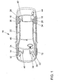
- FIG. 1 shows schematically in plan view a total of 10 designated motor vehicle. Structure and function of motor vehicles are well known, so that will not be discussed in the context of the present description.
- the motor vehicle 10 has four wheels 12, 14, 16 and 18.
- the wheels 12, 14, 16 and 18 are attached via a known suspension to a body 20 of the motor vehicle 10.
- Under construction 20 is understood in the context of the invention generally the vehicle body with the passenger compartment.
- a damper 22, 24, 26 and 28 are respectively arranged.
- the dampers 22, 24, 26 and 28 are arranged parallel to springs, not shown.
- the dampers 22, 24, 26 and 28 are for example designed as a semi-active damper, that is, by applying a control signal to an actuating means of the damper, the damper force can be varied.
- the adjusting means is usually designed as an electromagnetic valve, so that the control signal is a control current for the valve.
- Each wheel or damper is associated with a displacement sensor 30, 32, 34 and 36, respectively.
- the displacement sensors are designed as relative displacement sensors, that is to say they measure a change in the distance of the body 20 from the respective wheel 12, 14, 16 or 18.
- rotational angle displacement sensors are used whose construction and function are generally known.
- the structure 20 further comprises three vertical acceleration sensors 38, 40 and 42 arranged at defined points. These acceleration sensors 38, 40 and 42 are fixedly arranged on the structure 20 and measure the vertical acceleration of the structure in the area of the wheels 12, 14 and 18, respectively left rear wheel 16, the acceleration of the three other acceleration sensors can be calculated, so that can be dispensed with the arrangement of a separate acceleration sensor here.
- the arrangement of the sensors is merely exemplary here.
- Other sensor arrangements for example a vertical body acceleration sensor and two rotation angle sensors or the like, may also be used.
- the motor vehicle 10 further comprises a control unit 44 which is connected via signal or control lines to the adjusting means of the dampers 22, 24, 26 and 28, the displacement sensors 30, 32, 34 and 36 and the acceleration sensors 38, 40 and 42.
- the control unit 44 assumes the damper control, which will be explained in more detail below.
- the controller 44 can of course also take over other, not to be considered here functions within the motor vehicle 10.
- the motor vehicle 10 further comprises a switching means 46, for example a button, a rotary wheel or the like, by means of which a request for the movement of the body 20 can be selected by a vehicle driver.
- a switching means 46 for example a button, a rotary wheel or the like
- the switching means 46 is also connected to the control unit 44.
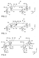
- FIG. 2 shows a schematic diagram of the motor vehicle 10, in which case the structure 20 is indicated as a flat surface.
- the wheels 12, 14, 16 and 18 are arranged in a manner known per se via a spring-damper combination.
- the spring-damper combination consists of the dampers 22, 24, 26 and 28 and parallel springs 48, 50, 52 and 54.
- At the corners of the structure 20 are the in FIG. 1 arranged acceleration sensors 38, 40 and 42, respectively, by means of which the vertical speed at the corners of the structure 20 can be determined. These are the speeds vA_vl (front-left speed), vA_vr (front-right speed), vA_hl (rear-left speed), and vA_hr (rear-right speed).
- the speed can be calculated from the accelerations measured by means of the acceleration sensors by integration.
- FIG. 3 again shows the schematic diagram of the motor vehicle 10, wherein the same parts as in the preceding figures provided with the same reference numerals and are not explained again.
- a center of gravity 56 the modal movements of the structure 20 are illustrated. This is on the one hand a stroke 58 in the vertical direction (z-direction), a pitch 61, that is a rotational movement about a transverse axis lying in the y-axis, and a roll 63, that is, a rotational movement about a lying in the x-axis Longitudinal axis of the motor vehicle 10.
- FIG. 4 shows a further schematic diagram of the motor vehicle 10, wherein here, in addition to the illustration in FIG. 2 , further signals are shown.
- the damper speeds vD are shown here, where vD_vl is the damper speed for the damper 22 (front left), vD_vr the damper speed for the damper 24 (front right), vD_hl the damper speed for the damper 26 (rear left) and vD_hr the damper speed for the Damper 28 (rear right) is.
- the damper speeds can be determined by differentiation from the signals of the displacement sensors 30, 32, 34 or 36 (FIG. FIG. 1 ) be determined.
- the wheel speeds vR are indicated.
- speed vR_vl stands for the wheel 12 (front left), vR_vr for the wheel 14 (front right), vR_hl for the wheel 16 (rear left) and vR_hr for the wheel 18 (rear right).
- the wheel speeds vR can be determined, for example, via wheel acceleration sensors.
- FIG. 5 shows the construction level 20 with the sensor positions S1 to S3. Furthermore, the Aktorangriffssee A1 to A4 are shown, where movements are to be calculated. Furthermore, an example of a virtual sensor positions A5 is given, which calculates, for example, the movement at the driver's seat.
- FIG. 6 shows the sensor movements occurring at the construction level 20, such as the body accelerations aS1 to aS3. From knowledge of these accelerations as well as the positions S1 to S3 and the position A5, the acceleration aA5 can now be calculated at A5.
- the invention thus relates to a method or control system component for transforming and / or redetermining signal or sensor variables, wherein the movement a body, in particular the movement of the body of a vehicle, is measured at at least three points of the body, and that means are provided which determine from the measured values the movement in at least an arbitrary fourth point of the body.
Landscapes
- Engineering & Computer Science (AREA)
- Mechanical Engineering (AREA)
- Physics & Mathematics (AREA)
- Automation & Control Theory (AREA)
- Mathematical Physics (AREA)
- Transportation (AREA)
- Vehicle Body Suspensions (AREA)
Applications Claiming Priority (1)
| Application Number | Priority Date | Filing Date | Title |
|---|---|---|---|
| DE102007051204.1A DE102007051204B4 (de) | 2007-10-26 | 2007-10-26 | Verfahren und Vorrichtung zur Bestimmung von Bewegungsgrößen, insbesondere von Aufbaubewegungen, eines Körpers |
Publications (3)
| Publication Number | Publication Date |
|---|---|
| EP2052888A2 true EP2052888A2 (fr) | 2009-04-29 |
| EP2052888A3 EP2052888A3 (fr) | 2014-08-20 |
| EP2052888B1 EP2052888B1 (fr) | 2018-09-26 |
Family
ID=40336628
Family Applications (1)
| Application Number | Title | Priority Date | Filing Date |
|---|---|---|---|
| EP08018571.3A Not-in-force EP2052888B1 (fr) | 2007-10-26 | 2008-10-23 | Procédé et système destinés à influencer le mouvement d'une caisse d'un véhicule automobile ou d'un véhicule, pouvant être commandée ou réglée dans ses déroulements de mouvements |
Country Status (2)
| Country | Link |
|---|---|
| EP (1) | EP2052888B1 (fr) |
| DE (1) | DE102007051204B4 (fr) |
Cited By (2)
| Publication number | Priority date | Publication date | Assignee | Title |
|---|---|---|---|---|
| EP2343203A3 (fr) * | 2009-12-16 | 2011-11-02 | Audi AG | Procédé de commande du fonctionnement d'un véhicule automobile et véhicule automobile |
| CN112793375A (zh) * | 2019-11-14 | 2021-05-14 | 上海保隆汽车科技股份有限公司 | 汽车阻尼连续可调半主动悬架电控装置及其控制方法 |
Families Citing this family (4)
| Publication number | Priority date | Publication date | Assignee | Title |
|---|---|---|---|---|
| DE102010046317A1 (de) | 2010-09-23 | 2012-03-29 | Audi Ag | Verfahren zum Einstellen der räumlichen Lage der Wankachse eines Kraftwagens |
| DE102012009882B4 (de) * | 2012-05-18 | 2015-07-16 | Audi Ag | Verfahren zur Steuerung eines aktiven Fahrwerks |
| JP6589943B2 (ja) * | 2017-06-29 | 2019-10-16 | トヨタ自動車株式会社 | 車両走行制御システム |
| DE102020202154A1 (de) * | 2020-02-19 | 2021-08-19 | Volkswagen Aktiengesellschaft | Ermitteln von Dynamikgrößen eines Fahrzeugs mit verteilt angeordneten Sensoren |
Citations (2)
| Publication number | Priority date | Publication date | Assignee | Title |
|---|---|---|---|---|
| DE3918735A1 (de) | 1989-06-08 | 1990-12-13 | Bosch Gmbh Robert | Verfahren und vorrichtung zur daempfung von bewegungsablaeufen |
| DE19600724C2 (de) | 1995-02-03 | 1998-03-26 | Mannesmann Sachs Ag | Verfahren zur Ermittlung von zur Quer- und/oder Längsbeschleunigung eines Fahrzeuges analogen Signalen |
Family Cites Families (6)
| Publication number | Priority date | Publication date | Assignee | Title |
|---|---|---|---|---|
| DE4201146C2 (de) * | 1991-01-18 | 2003-01-30 | Hitachi Ltd | Vorrichtung zur Steuerung des Kraftfahrzeugverhaltens |
| DE4117897C2 (de) * | 1991-05-31 | 2001-10-04 | Bosch Gmbh Robert | System zur Erzeugung von Signalen zur Steuerung oder Regelung eines in seinen Bewegungsabläufen steuerbaren oder regelbaren Fahrwerkes |
| JPH06344745A (ja) * | 1993-06-14 | 1994-12-20 | Aisin Seiki Co Ltd | サスペンション制御系の脱調検出装置 |
| DE19514844A1 (de) | 1994-05-02 | 1995-11-09 | Fichtel & Sachs Ag | Anordnung zur Steuerung einer Fahrwerk-Einrichtung |
| KR0181232B1 (ko) * | 1996-10-31 | 1999-03-20 | 오상수 | 차량의 반 능동 전자 제어 현가 장치 및 방법 |
| DE602005012400D1 (de) | 2005-11-09 | 2009-03-05 | Mando Corp | Methode zur Messung von Vertikalbeschleunigungen und -geschwindigkeiten für ein semiaktives Fahrwerk |
-
2007
- 2007-10-26 DE DE102007051204.1A patent/DE102007051204B4/de not_active Expired - Fee Related
-
2008
- 2008-10-23 EP EP08018571.3A patent/EP2052888B1/fr not_active Not-in-force
Patent Citations (2)
| Publication number | Priority date | Publication date | Assignee | Title |
|---|---|---|---|---|
| DE3918735A1 (de) | 1989-06-08 | 1990-12-13 | Bosch Gmbh Robert | Verfahren und vorrichtung zur daempfung von bewegungsablaeufen |
| DE19600724C2 (de) | 1995-02-03 | 1998-03-26 | Mannesmann Sachs Ag | Verfahren zur Ermittlung von zur Quer- und/oder Längsbeschleunigung eines Fahrzeuges analogen Signalen |
Cited By (3)
| Publication number | Priority date | Publication date | Assignee | Title |
|---|---|---|---|---|
| EP2343203A3 (fr) * | 2009-12-16 | 2011-11-02 | Audi AG | Procédé de commande du fonctionnement d'un véhicule automobile et véhicule automobile |
| CN112793375A (zh) * | 2019-11-14 | 2021-05-14 | 上海保隆汽车科技股份有限公司 | 汽车阻尼连续可调半主动悬架电控装置及其控制方法 |
| CN112793375B (zh) * | 2019-11-14 | 2025-05-30 | 上海保隆汽车科技股份有限公司 | 汽车阻尼连续可调半主动悬架电控装置及其控制方法 |
Also Published As
| Publication number | Publication date |
|---|---|
| DE102007051204B4 (de) | 2018-12-20 |
| DE102007051204A1 (de) | 2009-04-30 |
| EP2052888B1 (fr) | 2018-09-26 |
| EP2052888A3 (fr) | 2014-08-20 |
Similar Documents
| Publication | Publication Date | Title |
|---|---|---|
| DE10327593B4 (de) | System und Verfahren zum Bestimmen der Lage eines Kraftfahrzeuges | |
| DE10348738B4 (de) | Steuerungssystem für ein Kraftfahrzeug und Verfahren zum Steuern eines Kraftfahrzeugs | |
| DE102006016746B4 (de) | System zum Erfassen der Lage eines Kraftfahrzeugs relativ zur Straße | |
| DE102010003205B4 (de) | Verfahren zur Bestimmung der vertikalen Beschleunigung, der longitudinalen Winkelbeschleunigung und der transversalen Winkelbeschleunigung eines Körpers, insbesondere eines Kraftfahrzeugs | |
| DE10358335B3 (de) | Bestimmung von dynamischen Achslasten und/oder Radlasten eines Radfahrzeuges | |
| DE10327590A1 (de) | Verfahren und Apparat zum Kompensieren von Abweichungen eines Sensorsystems zum Einsatz in einem Fahrzeugdynamiksteuersystem | |
| DE102011080104A1 (de) | Fahrzeugaufbaulagesteuervorrichtung | |
| DE102008053008A1 (de) | Verfahren und System zur Beeinflussung der Bewegung eines in seinen Bewegungsabläufen steuerbaren oder regelbaren Fahrzeugaufbaus eines Kraftfahrzeuges und Fahrzeug | |
| EP2052888B1 (fr) | Procédé et système destinés à influencer le mouvement d'une caisse d'un véhicule automobile ou d'un véhicule, pouvant être commandée ou réglée dans ses déroulements de mouvements | |
| EP2212133B1 (fr) | Procédé destinés à influencer le mouvement d'une structure de véhicule motorisé pouvant être commandée ou régulée dans ses processus de mouvement | |
| EP1697189A1 (fr) | Procede et dispositif pour determiner l'etat d'un vehicule | |
| DE4116118C2 (de) | System zur Erzeugung von Signalen zur Steuerung oder Regelung eines steuerbaren oder regelbaren Fahrwerkes | |
| DE102009009888A1 (de) | Verfahren zur Regelung eines Fahrwerks eines Fahrzeugs | |
| EP1451030A1 (fr) | Reglage de position d'un corps de voiture d'un vehicule | |
| DE102016206604B4 (de) | Steuervorrichtung und Verfahren zum Regeln einer Dämpferhärte eines Schwingungsdämpfers eines Kraftfahrzeugs | |
| EP1283149B1 (fr) | Procédé et appareil de stabilisation de direction de véhicules articulés, en particulier autobus articulé | |
| EP1691994B1 (fr) | Determination d'un mouvement relatif entre le chassis et la carrosserie d'un vehicule a roues | |
| DE102012009882B4 (de) | Verfahren zur Steuerung eines aktiven Fahrwerks | |
| EP2052885B1 (fr) | Procédé et système destinés à influencer le mouvement d'une caisse d'un véhicule automobile ou d'un véhicule, pouvant être commandée ou réglée dans ses déroulements de mouvements | |
| DE10316114A1 (de) | Aktive Wankdämpfung | |
| DE102008052993A1 (de) | Verfahren und System zur Beeinflussung der Bewegung eines in seinen Bewegungsabläufen steuerbaren oder regelbaren Fahrzeugaufbaus eines Kraftfahrzeuges und Fahrzeug | |
| EP4107016B1 (fr) | Détermination de grandeurs dynamiques d'un véhicule au moyen de capteurs agencés de manière répartie | |
| DE19600724C2 (de) | Verfahren zur Ermittlung von zur Quer- und/oder Längsbeschleunigung eines Fahrzeuges analogen Signalen | |
| EP2052887B1 (fr) | Procédé et système destinés à influencer le mouvement d'une caisse d'un véhicule automobile ou d'un véhicule, pouvant être commandée ou réglée dans ses déroulements de mouvements | |
| DE10329278A1 (de) | Stabilisierungsvorrichtung, damit ausgestattetes Fahrzeug und Stabilisierungsverfahren |
Legal Events
| Date | Code | Title | Description |
|---|---|---|---|
| PUAI | Public reference made under article 153(3) epc to a published international application that has entered the european phase |
Free format text: ORIGINAL CODE: 0009012 |
|
| AK | Designated contracting states |
Kind code of ref document: A2 Designated state(s): AT BE BG CH CY CZ DE DK EE ES FI FR GB GR HR HU IE IS IT LI LT LU LV MC MT NL NO PL PT RO SE SI SK TR |
|
| AX | Request for extension of the european patent |
Extension state: AL BA MK RS |
|
| RAP1 | Party data changed (applicant data changed or rights of an application transferred) |
Owner name: VOLKSWAGEN AKTIENGESELLSCHAFT |
|
| PUAL | Search report despatched |
Free format text: ORIGINAL CODE: 0009013 |
|
| AK | Designated contracting states |
Kind code of ref document: A3 Designated state(s): AT BE BG CH CY CZ DE DK EE ES FI FR GB GR HR HU IE IS IT LI LT LU LV MC MT NL NO PL PT RO SE SI SK TR |
|
| AX | Request for extension of the european patent |
Extension state: AL BA MK RS |
|
| RIC1 | Information provided on ipc code assigned before grant |
Ipc: B60W 40/06 20120101ALN20140717BHEP Ipc: B60G 17/018 20060101ALI20140717BHEP Ipc: B60W 10/22 20060101ALN20140717BHEP Ipc: B60G 17/06 20060101ALN20140717BHEP Ipc: B60G 17/0165 20060101AFI20140717BHEP Ipc: B60W 40/10 20120101ALN20140717BHEP |
|
| 17P | Request for examination filed |
Effective date: 20150220 |
|
| RBV | Designated contracting states (corrected) |
Designated state(s): AT BE BG CH CY CZ DE DK EE ES FI FR GB GR HR HU IE IS IT LI LT LU LV MC MT NL NO PL PT RO SE SI SK TR |
|
| AKX | Designation fees paid |
Designated state(s): AT BE BG CH CY CZ DE DK EE ES FI FR GB GR HR HU IE IS IT LI LT LU LV MC MT NL NO PL PT RO SE SI SK TR |
|
| AXX | Extension fees paid |
Extension state: BA Extension state: AL Extension state: MK Extension state: RS |
|
| 17Q | First examination report despatched |
Effective date: 20170223 |
|
| GRAP | Despatch of communication of intention to grant a patent |
Free format text: ORIGINAL CODE: EPIDOSNIGR1 |
|
| RIC1 | Information provided on ipc code assigned before grant |
Ipc: B60W 40/10 20060101ALN20180518BHEP Ipc: B60G 17/06 20060101ALN20180518BHEP Ipc: B60G 17/018 20060101ALI20180518BHEP Ipc: B60W 40/06 20060101ALN20180518BHEP Ipc: B60W 10/22 20060101ALN20180518BHEP Ipc: B60G 17/0165 20060101AFI20180518BHEP |
|
| INTG | Intention to grant announced |
Effective date: 20180612 |
|
| GRAS | Grant fee paid |
Free format text: ORIGINAL CODE: EPIDOSNIGR3 |
|
| GRAA | (expected) grant |
Free format text: ORIGINAL CODE: 0009210 |
|
| AK | Designated contracting states |
Kind code of ref document: B1 Designated state(s): AT BE BG CH CY CZ DE DK EE ES FI FR GB GR HR HU IE IS IT LI LT LU LV MC MT NL NO PL PT RO SE SI SK TR |
|
| REG | Reference to a national code |
Ref country code: GB Ref legal event code: FG4D Free format text: NOT ENGLISH |
|
| REG | Reference to a national code |
Ref country code: CH Ref legal event code: EP |
|
| REG | Reference to a national code |
Ref country code: AT Ref legal event code: REF Ref document number: 1045562 Country of ref document: AT Kind code of ref document: T Effective date: 20181015 |
|
| REG | Reference to a national code |
Ref country code: IE Ref legal event code: FG4D Free format text: LANGUAGE OF EP DOCUMENT: GERMAN |
|
| REG | Reference to a national code |
Ref country code: DE Ref legal event code: R096 Ref document number: 502008016360 Country of ref document: DE |
|
| REG | Reference to a national code |
Ref country code: FR Ref legal event code: PLFP Year of fee payment: 11 |
|
| REG | Reference to a national code |
Ref country code: NL Ref legal event code: MP Effective date: 20180926 |
|
| PG25 | Lapsed in a contracting state [announced via postgrant information from national office to epo] |
Ref country code: LT Free format text: LAPSE BECAUSE OF FAILURE TO SUBMIT A TRANSLATION OF THE DESCRIPTION OR TO PAY THE FEE WITHIN THE PRESCRIBED TIME-LIMIT Effective date: 20180926 Ref country code: BG Free format text: LAPSE BECAUSE OF FAILURE TO SUBMIT A TRANSLATION OF THE DESCRIPTION OR TO PAY THE FEE WITHIN THE PRESCRIBED TIME-LIMIT Effective date: 20181226 Ref country code: SE Free format text: LAPSE BECAUSE OF FAILURE TO SUBMIT A TRANSLATION OF THE DESCRIPTION OR TO PAY THE FEE WITHIN THE PRESCRIBED TIME-LIMIT Effective date: 20180926 Ref country code: GR Free format text: LAPSE BECAUSE OF FAILURE TO SUBMIT A TRANSLATION OF THE DESCRIPTION OR TO PAY THE FEE WITHIN THE PRESCRIBED TIME-LIMIT Effective date: 20181227 Ref country code: FI Free format text: LAPSE BECAUSE OF FAILURE TO SUBMIT A TRANSLATION OF THE DESCRIPTION OR TO PAY THE FEE WITHIN THE PRESCRIBED TIME-LIMIT Effective date: 20180926 Ref country code: NO Free format text: LAPSE BECAUSE OF FAILURE TO SUBMIT A TRANSLATION OF THE DESCRIPTION OR TO PAY THE FEE WITHIN THE PRESCRIBED TIME-LIMIT Effective date: 20181226 |
|
| REG | Reference to a national code |
Ref country code: LT Ref legal event code: MG4D |
|
| PG25 | Lapsed in a contracting state [announced via postgrant information from national office to epo] |
Ref country code: HR Free format text: LAPSE BECAUSE OF FAILURE TO SUBMIT A TRANSLATION OF THE DESCRIPTION OR TO PAY THE FEE WITHIN THE PRESCRIBED TIME-LIMIT Effective date: 20180926 Ref country code: LV Free format text: LAPSE BECAUSE OF FAILURE TO SUBMIT A TRANSLATION OF THE DESCRIPTION OR TO PAY THE FEE WITHIN THE PRESCRIBED TIME-LIMIT Effective date: 20180926 |
|
| PG25 | Lapsed in a contracting state [announced via postgrant information from national office to epo] |
Ref country code: RO Free format text: LAPSE BECAUSE OF FAILURE TO SUBMIT A TRANSLATION OF THE DESCRIPTION OR TO PAY THE FEE WITHIN THE PRESCRIBED TIME-LIMIT Effective date: 20180926 Ref country code: IT Free format text: LAPSE BECAUSE OF FAILURE TO SUBMIT A TRANSLATION OF THE DESCRIPTION OR TO PAY THE FEE WITHIN THE PRESCRIBED TIME-LIMIT Effective date: 20180926 Ref country code: CZ Free format text: LAPSE BECAUSE OF FAILURE TO SUBMIT A TRANSLATION OF THE DESCRIPTION OR TO PAY THE FEE WITHIN THE PRESCRIBED TIME-LIMIT Effective date: 20180926 Ref country code: IS Free format text: LAPSE BECAUSE OF FAILURE TO SUBMIT A TRANSLATION OF THE DESCRIPTION OR TO PAY THE FEE WITHIN THE PRESCRIBED TIME-LIMIT Effective date: 20190126 Ref country code: PL Free format text: LAPSE BECAUSE OF FAILURE TO SUBMIT A TRANSLATION OF THE DESCRIPTION OR TO PAY THE FEE WITHIN THE PRESCRIBED TIME-LIMIT Effective date: 20180926 Ref country code: ES Free format text: LAPSE BECAUSE OF FAILURE TO SUBMIT A TRANSLATION OF THE DESCRIPTION OR TO PAY THE FEE WITHIN THE PRESCRIBED TIME-LIMIT Effective date: 20180926 Ref country code: NL Free format text: LAPSE BECAUSE OF FAILURE TO SUBMIT A TRANSLATION OF THE DESCRIPTION OR TO PAY THE FEE WITHIN THE PRESCRIBED TIME-LIMIT Effective date: 20180926 Ref country code: EE Free format text: LAPSE BECAUSE OF FAILURE TO SUBMIT A TRANSLATION OF THE DESCRIPTION OR TO PAY THE FEE WITHIN THE PRESCRIBED TIME-LIMIT Effective date: 20180926 |
|
| PG25 | Lapsed in a contracting state [announced via postgrant information from national office to epo] |
Ref country code: SK Free format text: LAPSE BECAUSE OF FAILURE TO SUBMIT A TRANSLATION OF THE DESCRIPTION OR TO PAY THE FEE WITHIN THE PRESCRIBED TIME-LIMIT Effective date: 20180926 Ref country code: PT Free format text: LAPSE BECAUSE OF FAILURE TO SUBMIT A TRANSLATION OF THE DESCRIPTION OR TO PAY THE FEE WITHIN THE PRESCRIBED TIME-LIMIT Effective date: 20190126 |
|
| REG | Reference to a national code |
Ref country code: CH Ref legal event code: PL |
|
| REG | Reference to a national code |
Ref country code: BE Ref legal event code: MM Effective date: 20181031 |
|
| REG | Reference to a national code |
Ref country code: DE Ref legal event code: R097 Ref document number: 502008016360 Country of ref document: DE |
|
| PG25 | Lapsed in a contracting state [announced via postgrant information from national office to epo] |
Ref country code: LU Free format text: LAPSE BECAUSE OF NON-PAYMENT OF DUE FEES Effective date: 20181023 |
|
| REG | Reference to a national code |
Ref country code: IE Ref legal event code: MM4A |
|
| PG25 | Lapsed in a contracting state [announced via postgrant information from national office to epo] |
Ref country code: DK Free format text: LAPSE BECAUSE OF FAILURE TO SUBMIT A TRANSLATION OF THE DESCRIPTION OR TO PAY THE FEE WITHIN THE PRESCRIBED TIME-LIMIT Effective date: 20180926 Ref country code: MC Free format text: LAPSE BECAUSE OF FAILURE TO SUBMIT A TRANSLATION OF THE DESCRIPTION OR TO PAY THE FEE WITHIN THE PRESCRIBED TIME-LIMIT Effective date: 20180926 |
|
| PLBE | No opposition filed within time limit |
Free format text: ORIGINAL CODE: 0009261 |
|
| STAA | Information on the status of an ep patent application or granted ep patent |
Free format text: STATUS: NO OPPOSITION FILED WITHIN TIME LIMIT |
|
| GBPC | Gb: european patent ceased through non-payment of renewal fee |
Effective date: 20181226 |
|
| PG25 | Lapsed in a contracting state [announced via postgrant information from national office to epo] |
Ref country code: BE Free format text: LAPSE BECAUSE OF NON-PAYMENT OF DUE FEES Effective date: 20181031 Ref country code: LI Free format text: LAPSE BECAUSE OF NON-PAYMENT OF DUE FEES Effective date: 20181031 Ref country code: CH Free format text: LAPSE BECAUSE OF NON-PAYMENT OF DUE FEES Effective date: 20181031 |
|
| 26N | No opposition filed |
Effective date: 20190627 |
|
| PG25 | Lapsed in a contracting state [announced via postgrant information from national office to epo] |
Ref country code: SI Free format text: LAPSE BECAUSE OF FAILURE TO SUBMIT A TRANSLATION OF THE DESCRIPTION OR TO PAY THE FEE WITHIN THE PRESCRIBED TIME-LIMIT Effective date: 20180926 Ref country code: IE Free format text: LAPSE BECAUSE OF NON-PAYMENT OF DUE FEES Effective date: 20181023 |
|
| REG | Reference to a national code |
Ref country code: AT Ref legal event code: MM01 Ref document number: 1045562 Country of ref document: AT Kind code of ref document: T Effective date: 20181023 |
|
| PG25 | Lapsed in a contracting state [announced via postgrant information from national office to epo] |
Ref country code: GB Free format text: LAPSE BECAUSE OF NON-PAYMENT OF DUE FEES Effective date: 20181226 |
|
| PG25 | Lapsed in a contracting state [announced via postgrant information from national office to epo] |
Ref country code: AT Free format text: LAPSE BECAUSE OF NON-PAYMENT OF DUE FEES Effective date: 20181023 Ref country code: MT Free format text: LAPSE BECAUSE OF FAILURE TO SUBMIT A TRANSLATION OF THE DESCRIPTION OR TO PAY THE FEE WITHIN THE PRESCRIBED TIME-LIMIT Effective date: 20180926 |
|
| PG25 | Lapsed in a contracting state [announced via postgrant information from national office to epo] |
Ref country code: TR Free format text: LAPSE BECAUSE OF FAILURE TO SUBMIT A TRANSLATION OF THE DESCRIPTION OR TO PAY THE FEE WITHIN THE PRESCRIBED TIME-LIMIT Effective date: 20180926 |
|
| PG25 | Lapsed in a contracting state [announced via postgrant information from national office to epo] |
Ref country code: CY Free format text: LAPSE BECAUSE OF FAILURE TO SUBMIT A TRANSLATION OF THE DESCRIPTION OR TO PAY THE FEE WITHIN THE PRESCRIBED TIME-LIMIT Effective date: 20180926 Ref country code: HU Free format text: LAPSE BECAUSE OF FAILURE TO SUBMIT A TRANSLATION OF THE DESCRIPTION OR TO PAY THE FEE WITHIN THE PRESCRIBED TIME-LIMIT; INVALID AB INITIO Effective date: 20081023 |
|
| PGFP | Annual fee paid to national office [announced via postgrant information from national office to epo] |
Ref country code: FR Payment date: 20221024 Year of fee payment: 15 |
|
| PGFP | Annual fee paid to national office [announced via postgrant information from national office to epo] |
Ref country code: DE Payment date: 20221031 Year of fee payment: 15 |
|
| P01 | Opt-out of the competence of the unified patent court (upc) registered |
Effective date: 20230523 |
|
| REG | Reference to a national code |
Ref country code: DE Ref legal event code: R119 Ref document number: 502008016360 Country of ref document: DE |
|
| PG25 | Lapsed in a contracting state [announced via postgrant information from national office to epo] |
Ref country code: FR Free format text: LAPSE BECAUSE OF NON-PAYMENT OF DUE FEES Effective date: 20231031 Ref country code: DE Free format text: LAPSE BECAUSE OF NON-PAYMENT OF DUE FEES Effective date: 20240501 |