EP2052893A2 - Réservoir d'eau pour un véhicule automobile et véhicule automobile doté d'un tel réservoir d'eau - Google Patents
Réservoir d'eau pour un véhicule automobile et véhicule automobile doté d'un tel réservoir d'eau Download PDFInfo
- Publication number
- EP2052893A2 EP2052893A2 EP08405313A EP08405313A EP2052893A2 EP 2052893 A2 EP2052893 A2 EP 2052893A2 EP 08405313 A EP08405313 A EP 08405313A EP 08405313 A EP08405313 A EP 08405313A EP 2052893 A2 EP2052893 A2 EP 2052893A2
- Authority
- EP
- European Patent Office
- Prior art keywords
- water tank
- pressure
- measuring means
- water
- tank according
- Prior art date
- Legal status (The legal status is an assumption and is not a legal conclusion. Google has not performed a legal analysis and makes no representation as to the accuracy of the status listed.)
- Granted
Links
Images

Classifications
-
- B—PERFORMING OPERATIONS; TRANSPORTING
- B62—LAND VEHICLES FOR TRAVELLING OTHERWISE THAN ON RAILS
- B62D—MOTOR VEHICLES; TRAILERS
- B62D25/00—Superstructure or monocoque structure sub-units; Parts or details thereof not otherwise provided for
- B62D25/08—Front or rear portions
- B62D25/081—Cowls
-
- B—PERFORMING OPERATIONS; TRANSPORTING
- B60—VEHICLES IN GENERAL
- B60H—ARRANGEMENTS OF HEATING, COOLING, VENTILATING OR OTHER AIR-TREATING DEVICES SPECIALLY ADAPTED FOR PASSENGER OR GOODS SPACES OF VEHICLES
- B60H1/00—Heating, cooling or ventilating devices
- B60H1/24—Ventilating devices where the heating or cooling is irrelevant
- B60H1/26—Ventilating openings in vehicle exterior; Ducts for conveying ventilating air
- B60H1/28—Ventilating openings in vehicle exterior; Ducts for conveying ventilating air the openings being situated directly in front of vehicle front window
Definitions
- the invention relates to a water tank for a motor vehicle, having an inlet opening at the top inlet, arranged in the installation position below the inlet opening interior with at least one trough-shaped recess having a bottom wall, in which at least one recess at least one outlet opening for discharging water is arranged ,
- Water tanks of this type have become known in numerous designs. They serve primarily to dissipate splash water that runs off along the windshield. The resulting water flow can be very significant, for example, in heavy rain or in a car wash. Such water boxes can also be used to separate water from a fresh air supply. Such a water tank is then also an air intake box. In the interior of the water box fresh air is diverted to separate water.
- a water tank of the type mentioned is for example from the EP-A-1 977 958 known.
- this has laterally openings. These openings are each provided with a one-way valve, each having a flap, which are pivoted at an overpressure in the water tank to the outside and thereby the opening is increased to drain the water.
- the water box also has openings for the supply of fresh air to the passenger compartment.
- the invention may be based on the object to provide a water tank of the type mentioned, which is still more reliable.
- the object is achieved according to claim 1, characterized in that it comprises at least one pressure-measuring means for controlling or regulating at least one unit.
- the Aggregate may be, for example, a valve, a fan, a motor, a heater or a flap. It is also possible to control several units. With such a pressure measuring means can be responded to disturbances that are due to a pressure change in the water tank, exactly and faster than before. For example, due to a pressure measurement by means of a valve, an outlet opening can be opened or closed. By way of example, a fan can also be controlled via said pressure measuring means.
- the inlet opening due to such a pressure measurement, for example by melting with a heating element snow or ice or to move by means of an aggregate, such as a motor or a knocking device, a grid, a flap or a filter of the inlet opening.
- an aggregate such as a motor or a knocking device, a grid, a flap or a filter of the inlet opening.
- the inlet opening can be made continuous again, if this should be clogged for example by snow, ice or foliage.
- the air supply to the interior of the water box can be ensured and an undesirably high negative pressure in the water tank can be avoided.
- flaps can be opened or closed in an air duct.
- the at least one pressure-measuring means may be arranged in the interior of the water box, but in principle also at another location, in particular in the bottom wall.
- the pressure measuring means may be arranged within the outlet opening, so that a water pressure can be measured with this.
- the at least one pressure-measuring means is arranged so that within a downcomer, a water pressure can be measured when this nozzle is at least partially filled with water. Due to the measured water pressure, a valve can be opened and thereby water can be discharged from this nozzle.
- the pressure measuring means may be formed in a conventional manner.
- the pressure measuring means as an electrical sensor or as a mechanical measuring means with a Membrane formed.
- the invention also relates to a motor vehicle with a water tank according to the invention.
- the water tank is connected via an air duct with an arranged in a front region of the motor vehicle air inlet.
- the unit is preferably designed so that the air passage in this channel can be changed on the basis of a pressure measurement.
- the unit is designed, for example, as a valve with which the air passage can be changed. The change takes place, for example, at a negative pressure or an overpressure in the interior of the water box.
- the nozzle forms a component with a sensor.
- the water box has a controllable flap as a valve for the supply of air into the interior.
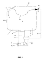
- the in FIG. 1 shown water tank 1 is according to FIG. 4 arranged in a motor vehicle 28 below a hood 15.
- the water tank 1 is located below a lower edge 18a of a windshield 18, so that water flowing from the windshield 18 can flow through an inlet opening 2 into an interior 3 of the water box 1.
- the inlet opening 2 is covered by a grid 14, so that leaves and larger objects can not get into the interior 3.
- the inlet opening 2 is located in a ceiling wall 38, which forms a water box cover.
- the grid 14 can be moved to remove any existing, the openings 2 clogging objects with a drive not shown here.
- a heating device for melting ice and snow For example, a heating wire in the grid 14 would be possible.
- the water tank 1 is made in the usual way of plastic and has a trough-shaped recess 4 with a bottom wall 5.
- the recess 4 also preferably extends along the lower edge of the window 18a. From the windscreen 18 effluent water can thus reach the recess 4.
- at least one outlet opening 6 is arranged in the bottom wall 5.
- the outlet opening 6 leads into a downwardly extending tubular nozzle 11.
- the opening 6 may be funnel-shaped or the like, so that the water from the depression 4 can flow completely into the nozzle 11.
- the opening 6 is closed at the lower end of the nozzle 11 with a valve 8.
- This valve 8 has a closure body 10, which is pivotable about a hinge 10a with a drive means 8a.
- the drive 8a is designed, for example, as an actuating cylinder and has a piston 9 which acts on the closure body 10.
- a control cylinder for example, a solenoid would be conceivable.
- the closure body 10 is formed here, for example, as a flap. Instead of a single nozzle 11, however, a plurality of nozzles 11 may be provided.
- the drive 8a is connected via a signal line 29 to a pressure measuring means 7.
- the pressure measuring means 7 is for example an electrical sensor or a known per se mechanical pressure measuring means. Located in the nozzle 11 water 12, so can with the Pressure measuring means the water pressure in the water 12 are measured. If this pressure exceeds a certain value, the pressure-measuring means 7 sends to the drive 8a a signal on the basis of which the valve 8 is opened. The water 12 can now flow through the open valve 8 from the nozzle 11. If the water has drained off, the pressure in the nozzle 11 drops correspondingly. If a predetermined value is undershot, the valve 8 is closed again due to a further signal.
- the pressure measuring means 7 can thus prevent by controlling the valve 8 that the interior 3 is flooded, for example, in heavy rainfall. Water could get into an opening 30, which the interior 3 according to FIG. 4 with a passenger compartment 27 connects. By the described control of the valve 8 due to a pressure measurement in the nozzle 11, this can be reliably prevented.
- the nozzle has the particular advantage that it can collect in this water with a comparatively small surface. From the air flowing through it little water is absorbed.
- the nozzle 11 can be made with the sensor 7 as a component and attached to the bottom wall 5, for example by means of a latching connection, not shown here. This has the advantage that the sensor 7 can be easily replaced if necessary.
- the production is particularly cost-effective when the sensor 7 is inserted into an injection mold and the nozzle 11 is molded onto the sensor 7.
- the length of the neck 11 is preferably at least 3 cm and the diameter is preferably 4 cm.
- the pressure measured in accordance with the pressure measuring means 7 drops.
- a negative pressure can be counteracted by a fan 32 arranged after the opening 30 being driven to a lower power. This power reduction takes place via a corresponding signal, which is output by the pressure measuring means 7 via a further signal line 31 to the fan 32.
- the measurement of the air pressure in the interior 3 can also take place via a further pressure measuring means, not shown here, which can be arranged above the opening 6 above. This in FIG. 1 shown pressure measuring means 7 may also be arranged above the opening 6 above. Also conceivable is an embodiment in which only the air pressure in the interior 3 is measured and due to the corresponding measurement of the fan. 2 is controlled.
- the pressure measuring means 7 is preferably designed so that it can measure both an overpressure and a negative pressure.
- the medium can be both air and water.
- FIG. 1 shows with an arrow 13 a possible way of fresh air from the inlet port 2 to the opening 30.
- the corresponding air flow can be enhanced by a higher power of the fan 32 or reduced by a lower power of the fan 32 accordingly. Due to the measurement of the pressure measuring means 7, this flow can thus be controlled or regulated.
- a flap 34 can be opened, which is connected via a signal line, not shown here with the sensor 7.
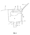
- FIG. 2 shows a water tank 1 ', which has an interior 3', which forms a deflection chamber for the fresh air supply.
- the fresh air is sucked through an inlet opening 2 'and flows around a guide wall 33, also called a baffle, as indicated by the arrow 17.
- the fresh air separates from this water and passes accordingly in a dry state to an opening 30 ', which leads to the passenger compartment 27.
- the opening 30 'in this case passes through a partition wall 19 which separates the passenger compartment 27 from the engine compartment.
- the interior 3 ' also has a recess 4' with a bottom wall 5 '.
- the pressure measuring means 7 may be formed as mentioned above and thus also be connected via said signal line 31 with said fan 32.
- the inlet opening 2 ' is used for the inlet of splash water, which flows down the front window 18 down.
- a grid 16 may be present here, which prevents larger objects from entering the interior space 3 '.
- a grille 16 ' may be provided which is arranged on or below the engine hood 15 and has inlet openings 2 "The grids 16 and 16' can also be moved with a drive, not shown here, possibly the grating 16 or 16 'to remove clogging objects.
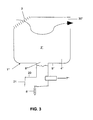
- FIG. 3 Water tank 1 "shown essentially corresponds to the water tank 1 according to the FIG. 1 , This thus also has an interior 3 ", a A trough-shaped depression 4 ", a bottom wall 5" and an outlet opening 6 "for splash water.
- a side pipe 20 is provided at the water tank 1", which is closable with a flap 21. If comparatively little splash water flows into the interior space 3 ", the flap 21 is pivoted on exceeding a certain pressure due to the water pressure, thereby opening the side nozzle 20. This water pressure is measured by the pressure measuring means 7" as mentioned above. If the water pressure exceeds a certain value, the pressure measuring means 7 “sends a signal to the valve 8", whereby the valve 8 "is opened, and the water can then flow out simultaneously through the side nozzle 20 and through the valve 8".
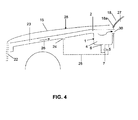
- motor vehicle 28 has a front opening 22, for example, in or behind a grille, through which air can pass into an air duct 23.
- This air duct 23 is connected to the above-mentioned water tank 1. Air can thus according to arrow 26 from the opening 22 into the water tank 1 arrive.
- a flap 24 is arranged, which is connected via a signal line 25 to the pressure measuring means 7.
- the pressure measuring means 7 measures the air pressure in the water tank 1.
- the pressure measuring means 7 can be arranged correspondingly also further up in the recess 4. Due to the determined air pressure, the flap 24 is controlled via the signal line 25. By setting the flap 24 accordingly, the influx of air to the water box 1 can be controlled.
- the flap 24 may be formed as any valve per se, which has a corresponding drive or an actuator with which the closure body can be actuated.
- the front opening 22 is provided with a flap 35 so that the average of air through the front opening 22 into the air duct 23 is controllable.
- the flap 35 is movable with a drive, not shown here, which is connected via a signal line 36 to the pressure sensor 7.
- FIG. 5 shown water box 1 '" has an outlet opening 6'', which is arranged in a side wall 37.
- a bottom wall 5 ''' is inclined towards the horizontal to the outlet opening 6'', so that water in the water box 1''flows completely to the outlet opening 6''.
- a pressure sensor 7'' is arranged directly in front of the outlet opening 6'', with which a The pressure sensor 7 "'determines the water pressure and opens the flap 21'" as soon as it is activated via a corresponding signal determined water pressure is determined.
Landscapes
- Engineering & Computer Science (AREA)
- Mechanical Engineering (AREA)
- Chemical & Material Sciences (AREA)
- Combustion & Propulsion (AREA)
- Transportation (AREA)
- Physics & Mathematics (AREA)
- Thermal Sciences (AREA)
- Air-Conditioning For Vehicles (AREA)
- Details Of Reciprocating Pumps (AREA)
- Motor Or Generator Cooling System (AREA)
Priority Applications (4)
| Application Number | Priority Date | Filing Date | Title |
|---|---|---|---|
| EP10007709A EP2236332B1 (fr) | 2008-12-22 | 2008-12-22 | Réservoir d'eau pour un véhicule automobile et véhicule automobile doté d'un tel réservoir d'eau |
| AT08405313T ATE481259T1 (de) | 2008-12-22 | 2008-12-22 | Wasserkasten für ein kraftfahrzeug und kraftfahrzeug mit einem solchen wasserkasten |
| EP08405313A EP2052893B1 (fr) | 2008-12-22 | 2008-12-22 | Réservoir d'eau pour un véhicule automobile et véhicule automobile doté d'un tel réservoir d'eau |
| DE502008001304T DE502008001304D1 (de) | 2008-12-22 | 2008-12-22 | Wasserkasten für ein Kraftfahrzeug und Kraftfahrzeug mit einem solchen Wasserkasten |
Applications Claiming Priority (1)
| Application Number | Priority Date | Filing Date | Title |
|---|---|---|---|
| EP08405313A EP2052893B1 (fr) | 2008-12-22 | 2008-12-22 | Réservoir d'eau pour un véhicule automobile et véhicule automobile doté d'un tel réservoir d'eau |
Related Child Applications (1)
| Application Number | Title | Priority Date | Filing Date |
|---|---|---|---|
| EP10007709.8 Division-Into | 2010-07-24 |
Publications (3)
| Publication Number | Publication Date |
|---|---|
| EP2052893A2 true EP2052893A2 (fr) | 2009-04-29 |
| EP2052893A3 EP2052893A3 (fr) | 2009-07-01 |
| EP2052893B1 EP2052893B1 (fr) | 2010-09-15 |
Family
ID=40416772
Family Applications (2)
| Application Number | Title | Priority Date | Filing Date |
|---|---|---|---|
| EP08405313A Not-in-force EP2052893B1 (fr) | 2008-12-22 | 2008-12-22 | Réservoir d'eau pour un véhicule automobile et véhicule automobile doté d'un tel réservoir d'eau |
| EP10007709A Not-in-force EP2236332B1 (fr) | 2008-12-22 | 2008-12-22 | Réservoir d'eau pour un véhicule automobile et véhicule automobile doté d'un tel réservoir d'eau |
Family Applications After (1)
| Application Number | Title | Priority Date | Filing Date |
|---|---|---|---|
| EP10007709A Not-in-force EP2236332B1 (fr) | 2008-12-22 | 2008-12-22 | Réservoir d'eau pour un véhicule automobile et véhicule automobile doté d'un tel réservoir d'eau |
Country Status (3)
| Country | Link |
|---|---|
| EP (2) | EP2052893B1 (fr) |
| AT (1) | ATE481259T1 (fr) |
| DE (1) | DE502008001304D1 (fr) |
Cited By (4)
| Publication number | Priority date | Publication date | Assignee | Title |
|---|---|---|---|---|
| EP2650155A1 (fr) * | 2012-04-12 | 2013-10-16 | Weidmann Plastics Technology AG | Réservoir d'eau pour un véhicule automobile |
| EP2752317A1 (fr) | 2013-05-06 | 2014-07-09 | Weidmann Plastics Technology AG | Véhicule automobile doté d'un réservoir d'eau et d'un appareil de climatisation |
| CN111746428A (zh) * | 2020-07-08 | 2020-10-09 | 东风柳州汽车有限公司 | 汽车侧门排水机构 |
| DE202020102752U1 (de) | 2020-05-14 | 2021-08-17 | Dirk Bäder | Kraftfahrzeug |
Families Citing this family (3)
| Publication number | Priority date | Publication date | Assignee | Title |
|---|---|---|---|---|
| FR3097492B1 (fr) * | 2019-06-20 | 2021-05-21 | Psa Automobiles Sa | Véhicule avec une boîte à eau comportant un dispositif d’obturation partielle mobile de l’évacuation |
| EP4344915B1 (fr) * | 2022-09-28 | 2026-04-01 | Ningbo Geely Automobile Research & Development Co. Ltd. | Dispositif d'admission d'air |
| DE102024108414B4 (de) | 2024-03-25 | 2026-02-05 | Audi Aktiengesellschaft | Kraftfahrzeug mit einem Wasserkasten und beidseits einer Längsmittelachse ausgebildeter Ansaugöffnung in einem Deckelelement des Wasserkastens |
Citations (2)
| Publication number | Priority date | Publication date | Assignee | Title |
|---|---|---|---|---|
| DE102007013690A1 (de) | 2007-03-22 | 2007-11-22 | Daimlerchrysler Ag | Gehäuseteil für eine Heizungs- und/oder Klimaanlage |
| EP1977958A2 (fr) | 2007-04-05 | 2008-10-08 | Nissan Motor Co., Ltd. | Carrosserie de véhicule |
Family Cites Families (9)
| Publication number | Priority date | Publication date | Assignee | Title |
|---|---|---|---|---|
| JPS60243B2 (ja) * | 1977-02-15 | 1985-01-07 | トヨタ自動車株式会社 | 自動車のカウル部構造 |
| JPS60203521A (ja) * | 1984-03-27 | 1985-10-15 | Nissan Motor Co Ltd | 自動車の外気導入装置 |
| DE3942290C1 (en) * | 1989-12-21 | 1991-06-06 | Bayerische Motoren Werke Ag, 8000 Muenchen, De | Ventilation for motor vehicle - has air intake chamber with water sepg. box with outlet opened by separate control |
| DE4105031A1 (de) * | 1991-02-19 | 1992-09-03 | Daimler Benz Ag | Verfahren zur anpassung der leistung mehrerer in wirkungszusammenhang stehender elektrischer verbraucher in einem kraftfahrzeug |
| DE4234045C1 (de) * | 1992-10-09 | 1993-10-14 | Daimler Benz Ag | Luftzuführeinrichtung zur Heiz- oder Klimaanlage eines Kraftwagens |
| DE19756983C1 (de) * | 1997-12-20 | 1998-11-26 | Daimler Benz Ag | Luftzuführeinrichtung |
| DE19810861A1 (de) * | 1998-03-13 | 1999-09-16 | Behr Gmbh & Co | Vorrichtung für die Luftzuführung für ein Fahrzeug |
| DE102004055259B3 (de) * | 2004-11-16 | 2006-03-30 | Daimlerchrysler Ag | Luftzuführeinrichtung für die Fahrgastzelle eines Kraftfahrzeugs |
| DE102005045292A1 (de) * | 2005-09-22 | 2007-04-05 | Daimlerchrysler Ag | Entwässerungsanordnung für einen Hohlraum einer Kraftwagenkarosserie |
-
2008
- 2008-12-22 AT AT08405313T patent/ATE481259T1/de active
- 2008-12-22 EP EP08405313A patent/EP2052893B1/fr not_active Not-in-force
- 2008-12-22 DE DE502008001304T patent/DE502008001304D1/de active Active
- 2008-12-22 EP EP10007709A patent/EP2236332B1/fr not_active Not-in-force
Patent Citations (2)
| Publication number | Priority date | Publication date | Assignee | Title |
|---|---|---|---|---|
| DE102007013690A1 (de) | 2007-03-22 | 2007-11-22 | Daimlerchrysler Ag | Gehäuseteil für eine Heizungs- und/oder Klimaanlage |
| EP1977958A2 (fr) | 2007-04-05 | 2008-10-08 | Nissan Motor Co., Ltd. | Carrosserie de véhicule |
Cited By (5)
| Publication number | Priority date | Publication date | Assignee | Title |
|---|---|---|---|---|
| EP2650155A1 (fr) * | 2012-04-12 | 2013-10-16 | Weidmann Plastics Technology AG | Réservoir d'eau pour un véhicule automobile |
| EP2752317A1 (fr) | 2013-05-06 | 2014-07-09 | Weidmann Plastics Technology AG | Véhicule automobile doté d'un réservoir d'eau et d'un appareil de climatisation |
| DE202020102752U1 (de) | 2020-05-14 | 2021-08-17 | Dirk Bäder | Kraftfahrzeug |
| CN111746428A (zh) * | 2020-07-08 | 2020-10-09 | 东风柳州汽车有限公司 | 汽车侧门排水机构 |
| CN111746428B (zh) * | 2020-07-08 | 2022-04-01 | 东风柳州汽车有限公司 | 汽车侧门排水机构 |
Also Published As
| Publication number | Publication date |
|---|---|
| EP2236332B1 (fr) | 2012-05-16 |
| EP2236332A2 (fr) | 2010-10-06 |
| DE502008001304D1 (de) | 2010-10-28 |
| EP2052893A3 (fr) | 2009-07-01 |
| EP2052893B1 (fr) | 2010-09-15 |
| EP2236332A3 (fr) | 2010-10-13 |
| ATE481259T1 (de) | 2010-10-15 |
Similar Documents
| Publication | Publication Date | Title |
|---|---|---|
| EP2052893B1 (fr) | Réservoir d'eau pour un véhicule automobile et véhicule automobile doté d'un tel réservoir d'eau | |
| DE102014006597A1 (de) | Fahrzeug mit einem frontseitig angeordnetem Luftkanal sowie Verfahren zur Steuerung eines Luftstroms, insbesondere eines Kühlluftstroms | |
| DE102007022298A1 (de) | Unterbodenverkleidung für ein Kraftfahrzeug | |
| WO2013164260A1 (fr) | Boîte à eau pour véhicule automobile | |
| DE3010485C2 (de) | Kühleranordnung für Kraftfahrzeuge | |
| EP2594462B1 (fr) | Réservoir d'eau pour un véhicule automobile | |
| DE19756983C1 (de) | Luftzuführeinrichtung | |
| DE10248188B4 (de) | Aggregateraum in einem Kraftfahrzeug | |
| EP0517732B1 (fr) | Dispositif d'amenee d'air frais a l'interieur d'un vehicule a moteur | |
| DE102005045292A1 (de) | Entwässerungsanordnung für einen Hohlraum einer Kraftwagenkarosserie | |
| DE102012002109A1 (de) | Flächenlüfter | |
| DE10209132B4 (de) | Ansaugvorrichtung für Kaltluft | |
| DE1804607B2 (de) | Kuehlsystem fuer tauchfaehige fahrzeuge | |
| EP2650155B1 (fr) | Réservoir d'eau pour un véhicule automobile | |
| EP0434910B1 (fr) | Distributeur d'air de ventilation pour l'habitacle d'un véhicule automobile | |
| DE102015220709B4 (de) | Kraftfahrzeug | |
| EP2648974B1 (fr) | Dispositif de purge d'eau fraîche exempte de contamination dans un avion | |
| DE2424152A1 (de) | Belueftungseinrichtung fuer staelle | |
| DE102014107666A1 (de) | Drainagesystem zur ableitung von wasser aus einem lufteinlass und einem luftverteilungsgehäuse einer klimaanlage | |
| EP2818601B1 (fr) | Bouche d'entrée ajustable en position | |
| EP2752320B1 (fr) | Réservoir d'eau pour un véhicule automobile | |
| DE10326417B4 (de) | Anordnung einer Seitenscheibe eines Kraftfahrzeugs | |
| WO2020200707A1 (fr) | Élément d'étanchéité comportant une partie de recouvrement, porte de véhicule et véhicule comportant un élément d'étanchéité, procédé de fabrication d'élément d'étanchéité | |
| EP1964716B1 (fr) | Remorque de véhicule doté d'un système de ventilation spécial | |
| EP2752319B1 (fr) | Réservoir d'eau pour un véhicule automobile |
Legal Events
| Date | Code | Title | Description |
|---|---|---|---|
| PUAI | Public reference made under article 153(3) epc to a published international application that has entered the european phase |
Free format text: ORIGINAL CODE: 0009012 |
|
| AK | Designated contracting states |
Kind code of ref document: A2 Designated state(s): AT BE BG CH CY CZ DE DK EE ES FI FR GB GR HR HU IE IS IT LI LT LU LV MC MT NL NO PL PT RO SE SI SK TR |
|
| AX | Request for extension of the european patent |
Extension state: AL BA MK RS |
|
| PUAL | Search report despatched |
Free format text: ORIGINAL CODE: 0009013 |
|
| AK | Designated contracting states |
Kind code of ref document: A3 Designated state(s): AT BE BG CH CY CZ DE DK EE ES FI FR GB GR HR HU IE IS IT LI LT LU LV MC MT NL NO PL PT RO SE SI SK TR |
|
| AX | Request for extension of the european patent |
Extension state: AL BA MK RS |
|
| 17P | Request for examination filed |
Effective date: 20091024 |
|
| 17Q | First examination report despatched |
Effective date: 20091124 |
|
| AKX | Designation fees paid |
Designated state(s): AT BE BG CH CY CZ DE DK EE ES FI FR GB GR HR HU IE IS IT LI LT LU LV MC MT NL NO PL PT RO SE SI SK TR |
|
| GRAP | Despatch of communication of intention to grant a patent |
Free format text: ORIGINAL CODE: EPIDOSNIGR1 |
|
| GRAC | Information related to communication of intention to grant a patent modified |
Free format text: ORIGINAL CODE: EPIDOSCIGR1 |
|
| RIC1 | Information provided on ipc code assigned before grant |
Ipc: B62D 25/24 20060101ALI20100305BHEP Ipc: B62D 25/08 20060101ALI20100305BHEP Ipc: B60H 1/28 20060101AFI20100305BHEP |
|
| GRAS | Grant fee paid |
Free format text: ORIGINAL CODE: EPIDOSNIGR3 |
|
| GRAA | (expected) grant |
Free format text: ORIGINAL CODE: 0009210 |
|
| AK | Designated contracting states |
Kind code of ref document: B1 Designated state(s): AT BE BG CH CY CZ DE DK EE ES FI FR GB GR HR HU IE IS IT LI LT LU LV MC MT NL NO PL PT RO SE SI SK TR |
|
| REG | Reference to a national code |
Ref country code: GB Ref legal event code: FG4D Free format text: NOT ENGLISH Ref country code: CH Ref legal event code: EP |
|
| REG | Reference to a national code |
Ref country code: IE Ref legal event code: FG4D Free format text: LANGUAGE OF EP DOCUMENT: GERMAN |
|
| REF | Corresponds to: |
Ref document number: 502008001304 Country of ref document: DE Date of ref document: 20101028 Kind code of ref document: P |
|
| REG | Reference to a national code |
Ref country code: NL Ref legal event code: VDEP Effective date: 20100915 |
|
| PG25 | Lapsed in a contracting state [announced via postgrant information from national office to epo] |
Ref country code: FI Free format text: LAPSE BECAUSE OF FAILURE TO SUBMIT A TRANSLATION OF THE DESCRIPTION OR TO PAY THE FEE WITHIN THE PRESCRIBED TIME-LIMIT Effective date: 20100915 Ref country code: NO Free format text: LAPSE BECAUSE OF FAILURE TO SUBMIT A TRANSLATION OF THE DESCRIPTION OR TO PAY THE FEE WITHIN THE PRESCRIBED TIME-LIMIT Effective date: 20101215 Ref country code: LT Free format text: LAPSE BECAUSE OF FAILURE TO SUBMIT A TRANSLATION OF THE DESCRIPTION OR TO PAY THE FEE WITHIN THE PRESCRIBED TIME-LIMIT Effective date: 20100915 |
|
| LTIE | Lt: invalidation of european patent or patent extension |
Effective date: 20100915 |
|
| PG25 | Lapsed in a contracting state [announced via postgrant information from national office to epo] |
Ref country code: CY Free format text: LAPSE BECAUSE OF FAILURE TO SUBMIT A TRANSLATION OF THE DESCRIPTION OR TO PAY THE FEE WITHIN THE PRESCRIBED TIME-LIMIT Effective date: 20100915 Ref country code: SI Free format text: LAPSE BECAUSE OF FAILURE TO SUBMIT A TRANSLATION OF THE DESCRIPTION OR TO PAY THE FEE WITHIN THE PRESCRIBED TIME-LIMIT Effective date: 20100915 Ref country code: PL Free format text: LAPSE BECAUSE OF FAILURE TO SUBMIT A TRANSLATION OF THE DESCRIPTION OR TO PAY THE FEE WITHIN THE PRESCRIBED TIME-LIMIT Effective date: 20100915 Ref country code: HR Free format text: LAPSE BECAUSE OF FAILURE TO SUBMIT A TRANSLATION OF THE DESCRIPTION OR TO PAY THE FEE WITHIN THE PRESCRIBED TIME-LIMIT Effective date: 20100915 |
|
| PG25 | Lapsed in a contracting state [announced via postgrant information from national office to epo] |
Ref country code: LV Free format text: LAPSE BECAUSE OF FAILURE TO SUBMIT A TRANSLATION OF THE DESCRIPTION OR TO PAY THE FEE WITHIN THE PRESCRIBED TIME-LIMIT Effective date: 20100915 Ref country code: GR Free format text: LAPSE BECAUSE OF FAILURE TO SUBMIT A TRANSLATION OF THE DESCRIPTION OR TO PAY THE FEE WITHIN THE PRESCRIBED TIME-LIMIT Effective date: 20101216 Ref country code: SE Free format text: LAPSE BECAUSE OF FAILURE TO SUBMIT A TRANSLATION OF THE DESCRIPTION OR TO PAY THE FEE WITHIN THE PRESCRIBED TIME-LIMIT Effective date: 20100915 |
|
| REG | Reference to a national code |
Ref country code: IE Ref legal event code: FD4D |
|
| PG25 | Lapsed in a contracting state [announced via postgrant information from national office to epo] |
Ref country code: IE Free format text: LAPSE BECAUSE OF FAILURE TO SUBMIT A TRANSLATION OF THE DESCRIPTION OR TO PAY THE FEE WITHIN THE PRESCRIBED TIME-LIMIT Effective date: 20100915 |
|
| PG25 | Lapsed in a contracting state [announced via postgrant information from national office to epo] |
Ref country code: PT Free format text: LAPSE BECAUSE OF FAILURE TO SUBMIT A TRANSLATION OF THE DESCRIPTION OR TO PAY THE FEE WITHIN THE PRESCRIBED TIME-LIMIT Effective date: 20110117 Ref country code: NL Free format text: LAPSE BECAUSE OF FAILURE TO SUBMIT A TRANSLATION OF THE DESCRIPTION OR TO PAY THE FEE WITHIN THE PRESCRIBED TIME-LIMIT Effective date: 20100915 Ref country code: SK Free format text: LAPSE BECAUSE OF FAILURE TO SUBMIT A TRANSLATION OF THE DESCRIPTION OR TO PAY THE FEE WITHIN THE PRESCRIBED TIME-LIMIT Effective date: 20100915 Ref country code: IS Free format text: LAPSE BECAUSE OF FAILURE TO SUBMIT A TRANSLATION OF THE DESCRIPTION OR TO PAY THE FEE WITHIN THE PRESCRIBED TIME-LIMIT Effective date: 20110115 Ref country code: RO Free format text: LAPSE BECAUSE OF FAILURE TO SUBMIT A TRANSLATION OF THE DESCRIPTION OR TO PAY THE FEE WITHIN THE PRESCRIBED TIME-LIMIT Effective date: 20100915 Ref country code: EE Free format text: LAPSE BECAUSE OF FAILURE TO SUBMIT A TRANSLATION OF THE DESCRIPTION OR TO PAY THE FEE WITHIN THE PRESCRIBED TIME-LIMIT Effective date: 20100915 Ref country code: IT Free format text: LAPSE BECAUSE OF FAILURE TO SUBMIT A TRANSLATION OF THE DESCRIPTION OR TO PAY THE FEE WITHIN THE PRESCRIBED TIME-LIMIT Effective date: 20100915 Ref country code: CZ Free format text: LAPSE BECAUSE OF FAILURE TO SUBMIT A TRANSLATION OF THE DESCRIPTION OR TO PAY THE FEE WITHIN THE PRESCRIBED TIME-LIMIT Effective date: 20100915 |
|
| BERE | Be: lapsed |
Owner name: WEIDMANN PLASTICS TECHNOLOGY A.G. Effective date: 20101231 |
|
| PG25 | Lapsed in a contracting state [announced via postgrant information from national office to epo] |
Ref country code: ES Free format text: LAPSE BECAUSE OF FAILURE TO SUBMIT A TRANSLATION OF THE DESCRIPTION OR TO PAY THE FEE WITHIN THE PRESCRIBED TIME-LIMIT Effective date: 20101226 |
|
| PLBE | No opposition filed within time limit |
Free format text: ORIGINAL CODE: 0009261 |
|
| STAA | Information on the status of an ep patent application or granted ep patent |
Free format text: STATUS: NO OPPOSITION FILED WITHIN TIME LIMIT |
|
| PG25 | Lapsed in a contracting state [announced via postgrant information from national office to epo] |
Ref country code: MC Free format text: LAPSE BECAUSE OF NON-PAYMENT OF DUE FEES Effective date: 20101231 |
|
| 26N | No opposition filed |
Effective date: 20110616 |
|
| PG25 | Lapsed in a contracting state [announced via postgrant information from national office to epo] |
Ref country code: DK Free format text: LAPSE BECAUSE OF FAILURE TO SUBMIT A TRANSLATION OF THE DESCRIPTION OR TO PAY THE FEE WITHIN THE PRESCRIBED TIME-LIMIT Effective date: 20100915 |
|
| PG25 | Lapsed in a contracting state [announced via postgrant information from national office to epo] |
Ref country code: BE Free format text: LAPSE BECAUSE OF NON-PAYMENT OF DUE FEES Effective date: 20101231 |
|
| REG | Reference to a national code |
Ref country code: DE Ref legal event code: R097 Ref document number: 502008001304 Country of ref document: DE Effective date: 20110616 |
|
| PG25 | Lapsed in a contracting state [announced via postgrant information from national office to epo] |
Ref country code: MT Free format text: LAPSE BECAUSE OF FAILURE TO SUBMIT A TRANSLATION OF THE DESCRIPTION OR TO PAY THE FEE WITHIN THE PRESCRIBED TIME-LIMIT Effective date: 20100915 |
|
| PG25 | Lapsed in a contracting state [announced via postgrant information from national office to epo] |
Ref country code: HU Free format text: LAPSE BECAUSE OF FAILURE TO SUBMIT A TRANSLATION OF THE DESCRIPTION OR TO PAY THE FEE WITHIN THE PRESCRIBED TIME-LIMIT Effective date: 20110316 Ref country code: BG Free format text: LAPSE BECAUSE OF FAILURE TO SUBMIT A TRANSLATION OF THE DESCRIPTION OR TO PAY THE FEE WITHIN THE PRESCRIBED TIME-LIMIT Effective date: 20100915 Ref country code: LU Free format text: LAPSE BECAUSE OF NON-PAYMENT OF DUE FEES Effective date: 20101222 |
|
| PG25 | Lapsed in a contracting state [announced via postgrant information from national office to epo] |
Ref country code: TR Free format text: LAPSE BECAUSE OF FAILURE TO SUBMIT A TRANSLATION OF THE DESCRIPTION OR TO PAY THE FEE WITHIN THE PRESCRIBED TIME-LIMIT Effective date: 20100915 |
|
| REG | Reference to a national code |
Ref country code: CH Ref legal event code: PL |
|
| PG25 | Lapsed in a contracting state [announced via postgrant information from national office to epo] |
Ref country code: BG Free format text: LAPSE BECAUSE OF FAILURE TO SUBMIT A TRANSLATION OF THE DESCRIPTION OR TO PAY THE FEE WITHIN THE PRESCRIBED TIME-LIMIT Effective date: 20101215 |
|
| PG25 | Lapsed in a contracting state [announced via postgrant information from national office to epo] |
Ref country code: LI Free format text: LAPSE BECAUSE OF NON-PAYMENT OF DUE FEES Effective date: 20121231 Ref country code: CH Free format text: LAPSE BECAUSE OF NON-PAYMENT OF DUE FEES Effective date: 20121231 |
|
| REG | Reference to a national code |
Ref country code: AT Ref legal event code: MM01 Ref document number: 481259 Country of ref document: AT Kind code of ref document: T Effective date: 20131222 |
|
| PG25 | Lapsed in a contracting state [announced via postgrant information from national office to epo] |
Ref country code: AT Free format text: LAPSE BECAUSE OF NON-PAYMENT OF DUE FEES Effective date: 20131222 |
|
| REG | Reference to a national code |
Ref country code: FR Ref legal event code: PLFP Year of fee payment: 8 |
|
| REG | Reference to a national code |
Ref country code: FR Ref legal event code: PLFP Year of fee payment: 9 |
|
| PGFP | Annual fee paid to national office [announced via postgrant information from national office to epo] |
Ref country code: GB Payment date: 20161222 Year of fee payment: 9 |
|
| PGFP | Annual fee paid to national office [announced via postgrant information from national office to epo] |
Ref country code: FR Payment date: 20161222 Year of fee payment: 9 |
|
| GBPC | Gb: european patent ceased through non-payment of renewal fee |
Effective date: 20171222 |
|
| REG | Reference to a national code |
Ref country code: FR Ref legal event code: ST Effective date: 20180831 |
|
| PG25 | Lapsed in a contracting state [announced via postgrant information from national office to epo] |
Ref country code: FR Free format text: LAPSE BECAUSE OF NON-PAYMENT OF DUE FEES Effective date: 20180102 |
|
| PG25 | Lapsed in a contracting state [announced via postgrant information from national office to epo] |
Ref country code: GB Free format text: LAPSE BECAUSE OF NON-PAYMENT OF DUE FEES Effective date: 20171222 |
|
| PGFP | Annual fee paid to national office [announced via postgrant information from national office to epo] |
Ref country code: DE Payment date: 20191210 Year of fee payment: 12 |
|
| REG | Reference to a national code |
Ref country code: DE Ref legal event code: R119 Ref document number: 502008001304 Country of ref document: DE |
|
| PG25 | Lapsed in a contracting state [announced via postgrant information from national office to epo] |
Ref country code: DE Free format text: LAPSE BECAUSE OF NON-PAYMENT OF DUE FEES Effective date: 20210701 |