EP2650155A1 - Réservoir d'eau pour un véhicule automobile - Google Patents
Réservoir d'eau pour un véhicule automobile Download PDFInfo
- Publication number
- EP2650155A1 EP2650155A1 EP12163910.8A EP12163910A EP2650155A1 EP 2650155 A1 EP2650155 A1 EP 2650155A1 EP 12163910 A EP12163910 A EP 12163910A EP 2650155 A1 EP2650155 A1 EP 2650155A1
- Authority
- EP
- European Patent Office
- Prior art keywords
- water tank
- water
- tank according
- wall
- air
- Prior art date
- Legal status (The legal status is an assumption and is not a legal conclusion. Google has not performed a legal analysis and makes no representation as to the accuracy of the status listed.)
- Granted
Links
Images


Classifications
-
- B—PERFORMING OPERATIONS; TRANSPORTING
- B60—VEHICLES IN GENERAL
- B60H—ARRANGEMENTS OF HEATING, COOLING, VENTILATING OR OTHER AIR-TREATING DEVICES SPECIALLY ADAPTED FOR PASSENGER OR GOODS SPACES OF VEHICLES
- B60H1/00—Heating, cooling or ventilating devices
- B60H1/24—Ventilating devices where the heating or cooling is irrelevant
- B60H1/26—Ventilating openings in vehicle exterior; Ducts for conveying ventilating air
- B60H1/28—Ventilating openings in vehicle exterior; Ducts for conveying ventilating air the openings being situated directly in front of vehicle front window
Definitions
- the invention relates to a water tank for a motor vehicle according to the preamble of claim 1.
- Water tanks of this type are arranged in motor vehicles, in particular below the engine guard and serve to suck for the air conditioning of the vehicle interior fresh air from the environment. For example, in the rain the sucked fresh air is laden with water droplets. In addition, splash water can enter the water box in the intake. So that the air conditioning system can be supplied with dry air as much as possible, both splash water and water droplets or aerosols from the fresh air should be conducted into the water drain opening in the bottom wall as effectively as possible and removed there. The efficiency of the separation of water should be as high as possible so that as few drops of water as possible get into the vehicle interior and in particular into the air filter of the air conditioning system.
- An increasingly important aspect of such a channel box is the energy required to draw in the fresh air and supply it to the air conditioning system.
- the fresh air is sucked in by means of a blower.
- the energy consumption depends in particular on the resistance experienced by the fresh air drawn in the water tank. By enlarging the water box, this resistance can be reduced. However, this is offset by the requirement that the volume of a water box should be as small as possible.
- an air-permeable roof body is arranged in the deflection chamber above the air outlet opening. This is on the one hand on a rear wall and on the other hand on a Front wall and forms with side walls flow openings.
- the air flowing through the water tank is deflected with two transverse directions.
- the high efficiency should be achieved by the fact that most of the entrained in the fresh air drops of water can not follow the double deflection on the roof body. It is assumed that, due to their inertia, the water droplets reach down into the water drain opening.
- the invention has for its object to provide a water tank of the type mentioned, which enables water separation with high efficiency, and can still be produced with a comparatively small volume.
- the water tank should have a relatively small resistance and thus ensure a comparatively small energy consumption in use.
- the deflecting essentially extends from the ceiling wall to the bottom wall, that the air inlet opening in the front wall and the air outlet opening are arranged in the rear wall and that between at least one side wall of the deflection chamber and a side edge of the Umlenkorgans a flow opening is arranged.
- the air flows essentially horizontally through the deflection chamber. Fresh air flowing through the air inlet opening into the deflection chamber is deflected at the deflection element and reaches the air outlet opening.
- the deflecting member At the front of the Umlenkorgans splash water is deflected and directed to the water outlet opening.
- the deflecting member extends substantially in the vertical direction.
- the efficiency of water separation is particularly high when, according to a development of the invention, the water drainage opening is arranged between the deflecting member and the rear wall. The water drain opening is then located on the leeward side of the deflection.
- the deflection member has a second side edge, which forms a second flow opening with a second side wall of the deflection chamber.
- These flow openings are preferably arranged substantially symmetrically, so that the fresh air flowing into the deflection chamber is divided symmetrically.
- the deflecting member is here in particular gabled roof-shaped. The ridge of the gable roof then extends substantially vertically. The two parts of the gable roof are preferably concave at the front.
- the deflecting member has a substantially vertically extending groove on the side edge, which is open to the front wall and can run down in the water. In this channel, the separated water can collect and enters this down and finally into the water outlet.
- This channel can be open at the bottom, so that the water can flow out efficiently here.
- a particularly low flow resistance can be achieved if, according to an embodiment of the invention, the air inlet opening and the air outlet opening are arranged substantially at the same height above the bottom wall. These two openings are thus arranged opposite each other here. The sucked fresh air flows substantially horizontally from the air inlet opening into the air outlet opening.
- the bottom wall is formed so conical that the water drain opening at a lowermost point of the bottom wall located. The splash water and the water separated from the air then reach the water drainage opening particularly efficiently.
- the deflection chamber has at least partially rounded edges between walls.
- the resistance and thus the energy consumption can be further reduced.
- the deflecting member has at least one part which is adjustable between a first and a second position, wherein this part deflects air flowing in the first position for water separation and releases a passage in the second position, so that the air can flow through the deflection chamber as unhindered as possible. If the ambient air is dry, for example in rain-free weather in summer, water separation in the water tank is not required. In this case, at least a part of the deflecting member is in a position in which it offers no resistance to the air flowing through. This part is for example a wall, which is aligned in the second position parallel to the flow direction. According to a development of the invention, this at least one part is pivotable about a substantially vertical axis.
- two parts are provided which form the deflecting member and which are pivotable between two positions. In one position, they form the deflection element, at which, as explained above, water is separated from the fresh air. In the other position, these two parts are pivoted so that they cause substantially no deflection of the air flowing through.
- the two parts are similar to a hinged door mirror image of each other pivotally.
- the at least one movable part of the deflecting element is controlled, for example by means of a moisture sensor.
- the said part is then controlled, for example, so that it is pivoted away into an inactive position when the moisture content falls below a predetermined value. If the moisture value exceeds the said limit, the said part is again moved to the active or deflecting position, for example pivoted.
- the Umlenkorgans according to the Coand Effect is rounded.
- the water and / or air to be separated is conducted in a particularly effective manner around the deflection element into the water drain opening. With this effect, in particular an improved deflection can be achieved and an undesirable stall can be avoided.
- the deflecting member lies with its upper side on the ceiling wall and / or with its underside on the bottom wall or is directly connected to the ceiling wall and / or bottom wall.
- the deflecting member lies with its upper side continuously on the ceiling wall or is continuously connected directly to the ceiling wall, i. There is no gap or no openings between the deflecting member and the ceiling wall.
- the deflecting element preferably lies with its lower side continuously against the bottom wall or is connected continuously directly to the bottom wall.
- the deflection member rests both continuously on the ceiling wall as well as continuously on the bottom wall or is directly connected to these walls, even all incoming fresh air is deflected at the deflection and only then enters the air outlet opening. At the front of the Umlenkorgans all splash water is deflected and directed to the water outlet opening.
- the top and / or bottom of the deflecting member is at least partially spaced from the top wall or bottom wall. In this case, the deflecting member at its top and / or bottom, for. be laterally connected to at least one of the side walls, without an immediate connection between the deflecting member and the top wall or bottom wall.
- the invention also relates to a motor vehicle with a water tank according to the invention.
- the water tank is connected to an air intake device, can be dispensed with the intake fresh air into the passenger compartment.
- the air intake device is preferably part of an air conditioner and has a per se conventional blower.
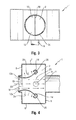
- the in the Fig. 1 to 4 Water tank 1 shown has a deflection chamber 2, which has a top wall 3, a bottom wall 4, a front wall 5, a rear wall 6 and two substantially mutually parallel side walls 7 and 8.
- the front wall 5 has an air inlet opening 10, at which fresh air sucked in can be introduced into the deflection chamber 2.
- the front wall 5 is connected via a pipe 34 with a suction port, not shown here, which is arranged for example below a windshield and covered with a grid, not shown here.
- the tube 34 may be round in cross section as shown.
- the cross section may also have a different shape, for example, the cross section may be rectangular.
- the air inlet opening 10 may also extend over the entire height of the front wall 5. In the Fig. 1 The air thus flows from left to right in the deflection chamber. 2
- the sucked fresh air flows through the deflection chamber 2 and leaves it through an air outlet opening 11, which is arranged in the rear wall 6.
- This air outlet opening 11 is connected via a pipe 35 with a not shown here and conventional air conditioning.
- the tube 35 may also be circular in cross-section or for example also rectangular.
- air conditioning is usually a fan for sucking the fresh air, an air filter and means for heating or cooling the fresh air.
- the air conditioning is usually in the passenger compartment, while the water tank 1 is located for example in the engine compartment.
- the water box 1 is as shown substantially closed.
- the escaping air flows in Fig. 1 left to right.
- the incoming air and the outflowing air thus flow in substantially the same direction. When installed, this flow is essentially horizontal.
- the fresh air which is sucked in at the air inlet opening 10, deflected so that it deposits as much water as possible.
- the water can occur as a splash and / or as drops.
- the deflection chamber 2 can thus be flowed through by a 2-phase flow, which is the case in particular in rainy weather.
- a water drain opening 9 For separating the water is in the bottom wall 4 according Fig. 1 arranged a water drain opening 9.
- This water drain opening 9 is located behind a deflecting member 12.
- the bottom wall 4 may be flat or conical, so that the water drain opening 9 is located at the lowest point of the bottom wall 4.
- the deflecting member 12 is gable roof-shaped and extends vertically from the top wall 3 to the bottom wall 4.
- the deflecting member 12 is located with a top 16 continuously on the ceiling wall 3 and with a bottom 17 continuously at the bottom wall 4 at. It consists of two essentially mirror-symmetrical parts 12a, which meet in a vertically extending front edge 18.
- the parts 12a each have a concave front side 19 and a convex rear side 20.
- the two parts 12a each have a likewise vertically extending side edge 13. These are each surrounded by a groove 14 extending vertically and each to Front wall 5 are open.
- the corresponding openings 36 are slot-shaped and preferably extend over the entire height the deflection chamber 2.
- drainage openings 40 are likewise provided in the grooves 14, through which splash water and / or water droplets can or can flow away.
- the fresh air can flow around the deflecting member 12, the two grooves 14 are arranged so that between them and a side wall 7 and side wall 8, a flow opening 15 is present.
- the distance between the two grooves 14 is substantially greater than the distance of the grooves 14 to the nearest side wall 8 and 7.
- these flow openings 15 each extend over the entire height of the deflection chamber 2 and thus each of the bottom wall 4 to the ceiling wall. 3
- the two parts 12 a can according to the Fig. 4 each pivotable about a pivot axis 25.
- the parts 12a may in particular from the in Fig. 1 shown first position in the in Fig. 4 shown second position to be pivoted. In the in Fig. 4 shown second position, the two parts 12a are pivoted outwards, so that there is a passage 37 between them. This passage 37 makes it possible that the fresh air sucked in according to the arrows 23 can flow through the deflection chamber 2 substantially unhindered.
- pivoting the parts 12a in the direction of Arrows 24 are preferably simultaneously pivots the grooves 14, which are in this case firmly connected to the parts 12a.
- the two parts 12a can thus be pivoted similar to gullwing doors.
- the pivoting can be done manually or by motor. In the Fig. 4 shown position of the two parts 12a is then provided when the sucked fresh air is relatively dry, a water separation is therefore not necessary.
- the pivoting can be done due to a sensor, not shown here, for example due to a humidity sensor.
- the pivoting takes place, for example, on the basis of a given value, for example a predetermined moisture content of the intake fresh air.
- the sensor may be arranged, for example, in the air inlet opening 10 or in the air outlet opening 11.
- the arrangement of the parts 12a according to Fig. 4 has the significant advantage that the air resistance in the deflection chamber 2 is substantially smaller than in the arrangement according to the Fig. 1 to 3 , Since the resistance is much smaller, correspondingly less energy is required for the intake of fresh air, for example by an electrically operated fan.
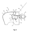
- the Fig. 5 shows a water tank 1 ', which is basically similar to the water tank 1 is formed.
- the water channels 14 'provided here are closed, at least in cross section, and in each case form a depression 38, which adjoins a front side 19' in each case.
- the drop-shaped cross-section grooves 14 ' are formed so that they have a particularly high Coand Effect. Splash water and drops of water deposited on the front side 19 'can thus flow around the deflection element 12 in a particularly efficient manner according to the arrows 26 and be directed into the water drainage opening 9.
- the dried air can leave the water tank 1 'according to the arrows 27.
- the water tank 1 ' also has as seen rounded edges 39, which connect the front wall 5' with the side walls 7 'and 8' and the rear wall 6 'with the side wall 7' and 8 '. These rounded edges 39 also reduce the resistance in the deflection chamber 2 'and also improve the discharge of water into the water drain opening 9.
- the two parts 12a can also be pivoted here. This is not mandatory. The two parts 12a can thus be permanently mounted here. This also applies to the parts 12 a of the water box 1.
- the in the Fig. 6 and 7 shown water tank 1 has a deflecting member 12", which is seen in section star-shaped.
- the deflecting member 12 consists of a fixed wall 30 and two limited pivotable wall-shaped parts 31.
- the parts 31 are each connected to an approximately circular cross-section groove 14".
- These gutters 14 can be used together with the part 31 of the in Fig. 6 shown position about an axis 29 in the in Fig. 7 shown position to be pivoted.
- This swing is in Fig. 7 indicated by the arrows 28.
- the position according to Fig. 7 is also provided here with comparatively dry outside air.
- the water tank 1 "'according to Fig. 8 has a diverter 12 '' extending inwardly from a side wall 7 '' into a diverting chamber 2 '''The diverter 12''has a concave front 19''' and a convex rear 20 '''.
- a channel 14" is arranged, which is closed in cross section. In principle, this groove 14 '"but also according to Fig. 1 be open.
- the concave front side 19 '"and the adjoining groove 14'' are in view of the Coand Effect designed rounded.
- Water and fresh air thus pass according to arrow 32 on the front side 19 "along the channel 14 '" and flows around this according to arrow 33. Water and fresh air flow through a flow opening 15 "' which extends between the channel 14 '" and a side wall 8'. Finally, the separated water is conducted along the convex back side 20 '"to the water discharge opening 9'.” The fresh air finally reaches the air conditioning system not shown here through the air outlet opening 11 '".
- the air inlet opening 10 '"and the air outlet opening 11'" are also arranged opposite one another.
- the fresh air sucked in flows through the deflection chamber 2 '' likewise substantially horizontally, and the deflection element 12 '' can be arranged fixedly or also pivotably.
- Motor vehicle 41 shown by way of example and in a highly schematic manner has a body 42, a windshield 43 and a bonnet 44 in the usual way.
- a grid 48 is arranged in an opening of the hood 44.
- An end wall 45 separates the interior of the motor vehicle 41 in a passenger compartment 46 and an engine compartment 47.
- a water tank 1 "" is arranged in the engine compartment 47.
- the water tank 1 "" has an air inlet opening 10 "", an air outlet opening 11 "", a water outlet opening 9 "” and a deflection chamber 2 "” on.
- a deflecting member 12 "" is arranged in the deflection chamber 2 ".
- the water tank 1 "" extends through an opening in the end wall 45 and is connected to a arranged in the passenger compartment 46 air intake device 49, which opens into the passenger compartment 46.
- a blower 50 is arranged in the housing 52 of the air intake 49.
- the blower 50 By means of the blower 50, as indicated by the arrow 51, sucked at the air inlet opening 10 "" of the water tank 1 “” air, transported through the water tank 1 "” and through the air intake 49 and discharged into the passenger compartment.
- the air flowing through the water tank 1 "" is deflected so that it deposits as much water as possible, which leaves the water box 1 "" via the water outlet opening 9 "".
- incoming splash water is also on the water outlet opening 9 "" from the water tank 1 "” deposited.
- a heater not shown here and a cooling device for the sucked air may be present, as is known per se from the prior art.
Landscapes
- Physics & Mathematics (AREA)
- Thermal Sciences (AREA)
- Engineering & Computer Science (AREA)
- Mechanical Engineering (AREA)
- Air-Conditioning For Vehicles (AREA)
Priority Applications (1)
| Application Number | Priority Date | Filing Date | Title |
|---|---|---|---|
| EP20120163910 EP2650155B1 (fr) | 2012-04-12 | 2012-04-12 | Réservoir d'eau pour un véhicule automobile |
Applications Claiming Priority (1)
| Application Number | Priority Date | Filing Date | Title |
|---|---|---|---|
| EP20120163910 EP2650155B1 (fr) | 2012-04-12 | 2012-04-12 | Réservoir d'eau pour un véhicule automobile |
Publications (2)
| Publication Number | Publication Date |
|---|---|
| EP2650155A1 true EP2650155A1 (fr) | 2013-10-16 |
| EP2650155B1 EP2650155B1 (fr) | 2014-07-02 |
Family
ID=46045769
Family Applications (1)
| Application Number | Title | Priority Date | Filing Date |
|---|---|---|---|
| EP20120163910 Active EP2650155B1 (fr) | 2012-04-12 | 2012-04-12 | Réservoir d'eau pour un véhicule automobile |
Country Status (1)
| Country | Link |
|---|---|
| EP (1) | EP2650155B1 (fr) |
Cited By (3)
| Publication number | Priority date | Publication date | Assignee | Title |
|---|---|---|---|---|
| EP2752320A1 (fr) * | 2013-09-16 | 2014-07-09 | Weidmann Plastics Technology AG | Réservoir d'eau pour un véhicule automobile |
| EP2752319A1 (fr) * | 2013-09-16 | 2014-07-09 | Weidmann Plastics Technology AG | Réservoir d'eau pour un véhicule automobile |
| CN114837861A (zh) * | 2022-03-29 | 2022-08-02 | 哈尔滨工程大学 | 一种v形防水结构 |
Citations (5)
| Publication number | Priority date | Publication date | Assignee | Title |
|---|---|---|---|---|
| FR1280008A (fr) * | 1960-11-15 | 1961-12-29 | Andre Citroen | Perfectionnements apportés à l'aération des véhicules |
| DE19923193C1 (de) | 1999-05-20 | 2000-07-06 | Daimler Chrysler Ag | Luftansaugvorrichtung |
| FR2878809A1 (fr) * | 2004-12-03 | 2006-06-09 | Renault Sas | Traverse pour support de pare-brise sur un vehicule automobile |
| DE102004051198B3 (de) | 2004-10-21 | 2006-06-22 | Daimlerchrysler Ag | Frischluftzuführvorrichtung |
| EP2052893A2 (fr) * | 2008-12-22 | 2009-04-29 | Weidmann Plastics Technology AG | Réservoir d'eau pour un véhicule automobile et véhicule automobile doté d'un tel réservoir d'eau |
-
2012
- 2012-04-12 EP EP20120163910 patent/EP2650155B1/fr active Active
Patent Citations (5)
| Publication number | Priority date | Publication date | Assignee | Title |
|---|---|---|---|---|
| FR1280008A (fr) * | 1960-11-15 | 1961-12-29 | Andre Citroen | Perfectionnements apportés à l'aération des véhicules |
| DE19923193C1 (de) | 1999-05-20 | 2000-07-06 | Daimler Chrysler Ag | Luftansaugvorrichtung |
| DE102004051198B3 (de) | 2004-10-21 | 2006-06-22 | Daimlerchrysler Ag | Frischluftzuführvorrichtung |
| FR2878809A1 (fr) * | 2004-12-03 | 2006-06-09 | Renault Sas | Traverse pour support de pare-brise sur un vehicule automobile |
| EP2052893A2 (fr) * | 2008-12-22 | 2009-04-29 | Weidmann Plastics Technology AG | Réservoir d'eau pour un véhicule automobile et véhicule automobile doté d'un tel réservoir d'eau |
Cited By (3)
| Publication number | Priority date | Publication date | Assignee | Title |
|---|---|---|---|---|
| EP2752320A1 (fr) * | 2013-09-16 | 2014-07-09 | Weidmann Plastics Technology AG | Réservoir d'eau pour un véhicule automobile |
| EP2752319A1 (fr) * | 2013-09-16 | 2014-07-09 | Weidmann Plastics Technology AG | Réservoir d'eau pour un véhicule automobile |
| CN114837861A (zh) * | 2022-03-29 | 2022-08-02 | 哈尔滨工程大学 | 一种v形防水结构 |
Also Published As
| Publication number | Publication date |
|---|---|
| EP2650155B1 (fr) | 2014-07-02 |
Similar Documents
| Publication | Publication Date | Title |
|---|---|---|
| DE19505213C1 (de) | Luftzuführeinrichtung | |
| DE4012568C1 (fr) | ||
| DE19835448B4 (de) | Klimaanlage | |
| EP3283353B1 (fr) | Ensemble formant capot de tablier pour un véhicule automobile | |
| WO2013164260A1 (fr) | Boîte à eau pour véhicule automobile | |
| DE102009048068A1 (de) | Ansaugeinheit einer Fahrzeugklimaanlage | |
| EP2594462B1 (fr) | Réservoir d'eau pour un véhicule automobile | |
| DE19756983C1 (de) | Luftzuführeinrichtung | |
| EP2710251B1 (fr) | Dispositif permettant de séparer l'eau de l'air de combustion destiné à être amené à un moteur à combustion interne | |
| EP2650155B1 (fr) | Réservoir d'eau pour un véhicule automobile | |
| EP2052893A2 (fr) | Réservoir d'eau pour un véhicule automobile et véhicule automobile doté d'un tel réservoir d'eau | |
| DE10248188B4 (de) | Aggregateraum in einem Kraftfahrzeug | |
| EP2752317B1 (fr) | Véhicule automobile doté d'une boîte d'eau et d'un appareil de climatisation | |
| DE10209132B4 (de) | Ansaugvorrichtung für Kaltluft | |
| DE19961316B4 (de) | Kraftfahrzeug mit einer heckseitigen Luftumlenkeinrichtung | |
| EP2752320B1 (fr) | Réservoir d'eau pour un véhicule automobile | |
| DE19923195C1 (de) | Luftansaugvorrichtung | |
| DE19923193C1 (de) | Luftansaugvorrichtung | |
| DE102008061538A1 (de) | Kanalanordnung zum Führen von Prozessluft zu einer Verbrennungskraftmaschine | |
| EP2752319B1 (fr) | Réservoir d'eau pour un véhicule automobile | |
| DE102005025566B3 (de) | Frischluftzuführ- und Wasserabscheideeinrichtung eines Kraftfahrzeugs | |
| DE3911515C2 (fr) | ||
| EP2752316B1 (fr) | Réservoir d'eau pour un véhicule automobile | |
| DE102023121352A1 (de) | Spoilervorrichtung | |
| DE102015014646A1 (de) | Wasserkastenabdeckung für ein Kraftfahrzeug |
Legal Events
| Date | Code | Title | Description |
|---|---|---|---|
| PUAI | Public reference made under article 153(3) epc to a published international application that has entered the european phase |
Free format text: ORIGINAL CODE: 0009012 |
|
| 17P | Request for examination filed |
Effective date: 20130222 |
|
| AK | Designated contracting states |
Kind code of ref document: A1 Designated state(s): AL AT BE BG CH CY CZ DE DK EE ES FI FR GB GR HR HU IE IS IT LI LT LU LV MC MK MT NL NO PL PT RO RS SE SI SK SM TR |
|
| AX | Request for extension of the european patent |
Extension state: BA ME |
|
| GRAP | Despatch of communication of intention to grant a patent |
Free format text: ORIGINAL CODE: EPIDOSNIGR1 |
|
| INTG | Intention to grant announced |
Effective date: 20140106 |
|
| GRAS | Grant fee paid |
Free format text: ORIGINAL CODE: EPIDOSNIGR3 |
|
| GRAA | (expected) grant |
Free format text: ORIGINAL CODE: 0009210 |
|
| AK | Designated contracting states |
Kind code of ref document: B1 Designated state(s): AL AT BE BG CH CY CZ DE DK EE ES FI FR GB GR HR HU IE IS IT LI LT LU LV MC MK MT NL NO PL PT RO RS SE SI SK SM TR |
|
| REG | Reference to a national code |
Ref country code: GB Ref legal event code: FG4D Free format text: NOT ENGLISH |
|
| REG | Reference to a national code |
Ref country code: CH Ref legal event code: EP Ref country code: AT Ref legal event code: REF Ref document number: 675710 Country of ref document: AT Kind code of ref document: T Effective date: 20140715 |
|
| REG | Reference to a national code |
Ref country code: IE Ref legal event code: FG4D Free format text: LANGUAGE OF EP DOCUMENT: GERMAN |
|
| REG | Reference to a national code |
Ref country code: CH Ref legal event code: NV Representative=s name: ISLER AND PEDRAZZINI AG, CH |
|
| REG | Reference to a national code |
Ref country code: DE Ref legal event code: R096 Ref document number: 502012000947 Country of ref document: DE Effective date: 20140814 |
|
| REG | Reference to a national code |
Ref country code: NL Ref legal event code: VDEP Effective date: 20140702 |
|
| REG | Reference to a national code |
Ref country code: SK Ref legal event code: T3 Ref document number: E 17075 Country of ref document: SK |
|
| REG | Reference to a national code |
Ref country code: LT Ref legal event code: MG4D |
|
| PG25 | Lapsed in a contracting state [announced via postgrant information from national office to epo] |
Ref country code: PT Free format text: LAPSE BECAUSE OF FAILURE TO SUBMIT A TRANSLATION OF THE DESCRIPTION OR TO PAY THE FEE WITHIN THE PRESCRIBED TIME-LIMIT Effective date: 20141103 Ref country code: ES Free format text: LAPSE BECAUSE OF FAILURE TO SUBMIT A TRANSLATION OF THE DESCRIPTION OR TO PAY THE FEE WITHIN THE PRESCRIBED TIME-LIMIT Effective date: 20140702 Ref country code: CZ Free format text: LAPSE BECAUSE OF FAILURE TO SUBMIT A TRANSLATION OF THE DESCRIPTION OR TO PAY THE FEE WITHIN THE PRESCRIBED TIME-LIMIT Effective date: 20140702 Ref country code: BG Free format text: LAPSE BECAUSE OF FAILURE TO SUBMIT A TRANSLATION OF THE DESCRIPTION OR TO PAY THE FEE WITHIN THE PRESCRIBED TIME-LIMIT Effective date: 20141002 Ref country code: GR Free format text: LAPSE BECAUSE OF FAILURE TO SUBMIT A TRANSLATION OF THE DESCRIPTION OR TO PAY THE FEE WITHIN THE PRESCRIBED TIME-LIMIT Effective date: 20141003 Ref country code: LT Free format text: LAPSE BECAUSE OF FAILURE TO SUBMIT A TRANSLATION OF THE DESCRIPTION OR TO PAY THE FEE WITHIN THE PRESCRIBED TIME-LIMIT Effective date: 20140702 Ref country code: NO Free format text: LAPSE BECAUSE OF FAILURE TO SUBMIT A TRANSLATION OF THE DESCRIPTION OR TO PAY THE FEE WITHIN THE PRESCRIBED TIME-LIMIT Effective date: 20141002 Ref country code: FI Free format text: LAPSE BECAUSE OF FAILURE TO SUBMIT A TRANSLATION OF THE DESCRIPTION OR TO PAY THE FEE WITHIN THE PRESCRIBED TIME-LIMIT Effective date: 20140702 Ref country code: SE Free format text: LAPSE BECAUSE OF FAILURE TO SUBMIT A TRANSLATION OF THE DESCRIPTION OR TO PAY THE FEE WITHIN THE PRESCRIBED TIME-LIMIT Effective date: 20140702 |
|
| PG25 | Lapsed in a contracting state [announced via postgrant information from national office to epo] |
Ref country code: HR Free format text: LAPSE BECAUSE OF FAILURE TO SUBMIT A TRANSLATION OF THE DESCRIPTION OR TO PAY THE FEE WITHIN THE PRESCRIBED TIME-LIMIT Effective date: 20140702 Ref country code: NL Free format text: LAPSE BECAUSE OF FAILURE TO SUBMIT A TRANSLATION OF THE DESCRIPTION OR TO PAY THE FEE WITHIN THE PRESCRIBED TIME-LIMIT Effective date: 20140702 Ref country code: CY Free format text: LAPSE BECAUSE OF FAILURE TO SUBMIT A TRANSLATION OF THE DESCRIPTION OR TO PAY THE FEE WITHIN THE PRESCRIBED TIME-LIMIT Effective date: 20140702 Ref country code: IS Free format text: LAPSE BECAUSE OF FAILURE TO SUBMIT A TRANSLATION OF THE DESCRIPTION OR TO PAY THE FEE WITHIN THE PRESCRIBED TIME-LIMIT Effective date: 20141102 Ref country code: PL Free format text: LAPSE BECAUSE OF FAILURE TO SUBMIT A TRANSLATION OF THE DESCRIPTION OR TO PAY THE FEE WITHIN THE PRESCRIBED TIME-LIMIT Effective date: 20140702 Ref country code: LV Free format text: LAPSE BECAUSE OF FAILURE TO SUBMIT A TRANSLATION OF THE DESCRIPTION OR TO PAY THE FEE WITHIN THE PRESCRIBED TIME-LIMIT Effective date: 20140702 Ref country code: RS Free format text: LAPSE BECAUSE OF FAILURE TO SUBMIT A TRANSLATION OF THE DESCRIPTION OR TO PAY THE FEE WITHIN THE PRESCRIBED TIME-LIMIT Effective date: 20140702 |
|
| REG | Reference to a national code |
Ref country code: DE Ref legal event code: R097 Ref document number: 502012000947 Country of ref document: DE |
|
| REG | Reference to a national code |
Ref country code: FR Ref legal event code: PLFP Year of fee payment: 4 |
|
| PG25 | Lapsed in a contracting state [announced via postgrant information from national office to epo] |
Ref country code: RO Free format text: LAPSE BECAUSE OF FAILURE TO SUBMIT A TRANSLATION OF THE DESCRIPTION OR TO PAY THE FEE WITHIN THE PRESCRIBED TIME-LIMIT Effective date: 20140702 Ref country code: IT Free format text: LAPSE BECAUSE OF FAILURE TO SUBMIT A TRANSLATION OF THE DESCRIPTION OR TO PAY THE FEE WITHIN THE PRESCRIBED TIME-LIMIT Effective date: 20140702 Ref country code: DK Free format text: LAPSE BECAUSE OF FAILURE TO SUBMIT A TRANSLATION OF THE DESCRIPTION OR TO PAY THE FEE WITHIN THE PRESCRIBED TIME-LIMIT Effective date: 20140702 Ref country code: EE Free format text: LAPSE BECAUSE OF FAILURE TO SUBMIT A TRANSLATION OF THE DESCRIPTION OR TO PAY THE FEE WITHIN THE PRESCRIBED TIME-LIMIT Effective date: 20140702 |
|
| PLBE | No opposition filed within time limit |
Free format text: ORIGINAL CODE: 0009261 |
|
| STAA | Information on the status of an ep patent application or granted ep patent |
Free format text: STATUS: NO OPPOSITION FILED WITHIN TIME LIMIT |
|
| 26N | No opposition filed |
Effective date: 20150407 |
|
| PG25 | Lapsed in a contracting state [announced via postgrant information from national office to epo] |
Ref country code: MC Free format text: LAPSE BECAUSE OF FAILURE TO SUBMIT A TRANSLATION OF THE DESCRIPTION OR TO PAY THE FEE WITHIN THE PRESCRIBED TIME-LIMIT Effective date: 20140702 Ref country code: LU Free format text: LAPSE BECAUSE OF FAILURE TO SUBMIT A TRANSLATION OF THE DESCRIPTION OR TO PAY THE FEE WITHIN THE PRESCRIBED TIME-LIMIT Effective date: 20150412 Ref country code: SI Free format text: LAPSE BECAUSE OF FAILURE TO SUBMIT A TRANSLATION OF THE DESCRIPTION OR TO PAY THE FEE WITHIN THE PRESCRIBED TIME-LIMIT Effective date: 20140702 |
|
| REG | Reference to a national code |
Ref country code: IE Ref legal event code: MM4A |
|
| REG | Reference to a national code |
Ref country code: FR Ref legal event code: PLFP Year of fee payment: 5 |
|
| PG25 | Lapsed in a contracting state [announced via postgrant information from national office to epo] |
Ref country code: IE Free format text: LAPSE BECAUSE OF NON-PAYMENT OF DUE FEES Effective date: 20150412 |
|
| PG25 | Lapsed in a contracting state [announced via postgrant information from national office to epo] |
Ref country code: MT Free format text: LAPSE BECAUSE OF FAILURE TO SUBMIT A TRANSLATION OF THE DESCRIPTION OR TO PAY THE FEE WITHIN THE PRESCRIBED TIME-LIMIT Effective date: 20140702 |
|
| REG | Reference to a national code |
Ref country code: FR Ref legal event code: PLFP Year of fee payment: 6 |
|
| PG25 | Lapsed in a contracting state [announced via postgrant information from national office to epo] |
Ref country code: SM Free format text: LAPSE BECAUSE OF FAILURE TO SUBMIT A TRANSLATION OF THE DESCRIPTION OR TO PAY THE FEE WITHIN THE PRESCRIBED TIME-LIMIT Effective date: 20140702 Ref country code: HU Free format text: LAPSE BECAUSE OF FAILURE TO SUBMIT A TRANSLATION OF THE DESCRIPTION OR TO PAY THE FEE WITHIN THE PRESCRIBED TIME-LIMIT; INVALID AB INITIO Effective date: 20120412 |
|
| PG25 | Lapsed in a contracting state [announced via postgrant information from national office to epo] |
Ref country code: BE Free format text: LAPSE BECAUSE OF NON-PAYMENT OF DUE FEES Effective date: 20150430 |
|
| PG25 | Lapsed in a contracting state [announced via postgrant information from national office to epo] |
Ref country code: TR Free format text: LAPSE BECAUSE OF FAILURE TO SUBMIT A TRANSLATION OF THE DESCRIPTION OR TO PAY THE FEE WITHIN THE PRESCRIBED TIME-LIMIT Effective date: 20140702 |
|
| REG | Reference to a national code |
Ref country code: FR Ref legal event code: PLFP Year of fee payment: 7 |
|
| REG | Reference to a national code |
Ref country code: AT Ref legal event code: MM01 Ref document number: 675710 Country of ref document: AT Kind code of ref document: T Effective date: 20170412 |
|
| PG25 | Lapsed in a contracting state [announced via postgrant information from national office to epo] |
Ref country code: MK Free format text: LAPSE BECAUSE OF FAILURE TO SUBMIT A TRANSLATION OF THE DESCRIPTION OR TO PAY THE FEE WITHIN THE PRESCRIBED TIME-LIMIT Effective date: 20140702 |
|
| PGFP | Annual fee paid to national office [announced via postgrant information from national office to epo] |
Ref country code: SK Payment date: 20180410 Year of fee payment: 7 Ref country code: CH Payment date: 20180411 Year of fee payment: 7 |
|
| PG25 | Lapsed in a contracting state [announced via postgrant information from national office to epo] |
Ref country code: AT Free format text: LAPSE BECAUSE OF NON-PAYMENT OF DUE FEES Effective date: 20170412 |
|
| PG25 | Lapsed in a contracting state [announced via postgrant information from national office to epo] |
Ref country code: AL Free format text: LAPSE BECAUSE OF FAILURE TO SUBMIT A TRANSLATION OF THE DESCRIPTION OR TO PAY THE FEE WITHIN THE PRESCRIBED TIME-LIMIT Effective date: 20140702 |
|
| PGFP | Annual fee paid to national office [announced via postgrant information from national office to epo] |
Ref country code: GB Payment date: 20180418 Year of fee payment: 7 |
|
| PGFP | Annual fee paid to national office [announced via postgrant information from national office to epo] |
Ref country code: FR Payment date: 20190418 Year of fee payment: 8 |
|
| REG | Reference to a national code |
Ref country code: CH Ref legal event code: PL |
|
| GBPC | Gb: european patent ceased through non-payment of renewal fee |
Effective date: 20190412 |
|
| REG | Reference to a national code |
Ref country code: SK Ref legal event code: MM4A Ref document number: E 17075 Country of ref document: SK Effective date: 20190412 |
|
| PG25 | Lapsed in a contracting state [announced via postgrant information from national office to epo] |
Ref country code: SK Free format text: LAPSE BECAUSE OF NON-PAYMENT OF DUE FEES Effective date: 20190412 Ref country code: CH Free format text: LAPSE BECAUSE OF NON-PAYMENT OF DUE FEES Effective date: 20190430 Ref country code: LI Free format text: LAPSE BECAUSE OF NON-PAYMENT OF DUE FEES Effective date: 20190430 Ref country code: GB Free format text: LAPSE BECAUSE OF NON-PAYMENT OF DUE FEES Effective date: 20190412 |
|
| PG25 | Lapsed in a contracting state [announced via postgrant information from national office to epo] |
Ref country code: FR Free format text: LAPSE BECAUSE OF NON-PAYMENT OF DUE FEES Effective date: 20200430 |
|
| PGFP | Annual fee paid to national office [announced via postgrant information from national office to epo] |
Ref country code: DE Payment date: 20250422 Year of fee payment: 14 |