EP2052919A1 - Sicherheitsvorrichtung mit Airbag für Kraftfahrzeug - Google Patents
Sicherheitsvorrichtung mit Airbag für Kraftfahrzeug Download PDFInfo
- Publication number
- EP2052919A1 EP2052919A1 EP08305682A EP08305682A EP2052919A1 EP 2052919 A1 EP2052919 A1 EP 2052919A1 EP 08305682 A EP08305682 A EP 08305682A EP 08305682 A EP08305682 A EP 08305682A EP 2052919 A1 EP2052919 A1 EP 2052919A1
- Authority
- EP
- European Patent Office
- Prior art keywords
- flap
- hinge
- axis
- pivoting
- rib
- Prior art date
- Legal status (The legal status is an assumption and is not a legal conclusion. Google has not performed a legal analysis and makes no representation as to the accuracy of the status listed.)
- Withdrawn
Links
Images


Classifications
-
- B—PERFORMING OPERATIONS; TRANSPORTING
- B60—VEHICLES IN GENERAL
- B60R—VEHICLES, VEHICLE FITTINGS, OR VEHICLE PARTS, NOT OTHERWISE PROVIDED FOR
- B60R21/00—Arrangements or fittings on vehicles for protecting or preventing injuries to occupants or pedestrians in case of accidents or other traffic risks
- B60R21/02—Occupant safety arrangements or fittings, e.g. crash pads
- B60R21/16—Inflatable occupant restraints or confinements designed to inflate upon impact or impending impact, e.g. air bags
- B60R21/20—Arrangements for storing inflatable members in their non-use or deflated condition; Arrangement or mounting of air bag modules or components
- B60R21/215—Arrangements for storing inflatable members in their non-use or deflated condition; Arrangement or mounting of air bag modules or components characterised by the covers for the inflatable member
-
- B—PERFORMING OPERATIONS; TRANSPORTING
- B60—VEHICLES IN GENERAL
- B60R—VEHICLES, VEHICLE FITTINGS, OR VEHICLE PARTS, NOT OTHERWISE PROVIDED FOR
- B60R21/00—Arrangements or fittings on vehicles for protecting or preventing injuries to occupants or pedestrians in case of accidents or other traffic risks
- B60R21/02—Occupant safety arrangements or fittings, e.g. crash pads
- B60R21/16—Inflatable occupant restraints or confinements designed to inflate upon impact or impending impact, e.g. air bags
- B60R21/20—Arrangements for storing inflatable members in their non-use or deflated condition; Arrangement or mounting of air bag modules or components
- B60R21/215—Arrangements for storing inflatable members in their non-use or deflated condition; Arrangement or mounting of air bag modules or components characterised by the covers for the inflatable member
- B60R21/216—Arrangements for storing inflatable members in their non-use or deflated condition; Arrangement or mounting of air bag modules or components characterised by the covers for the inflatable member comprising tether means for limitation of cover motion during deployment
-
- B—PERFORMING OPERATIONS; TRANSPORTING
- B60—VEHICLES IN GENERAL
- B60R—VEHICLES, VEHICLE FITTINGS, OR VEHICLE PARTS, NOT OTHERWISE PROVIDED FOR
- B60R21/00—Arrangements or fittings on vehicles for protecting or preventing injuries to occupants or pedestrians in case of accidents or other traffic risks
- B60R21/02—Occupant safety arrangements or fittings, e.g. crash pads
- B60R21/16—Inflatable occupant restraints or confinements designed to inflate upon impact or impending impact, e.g. air bags
- B60R21/20—Arrangements for storing inflatable members in their non-use or deflated condition; Arrangement or mounting of air bag modules or components
- B60R21/215—Arrangements for storing inflatable members in their non-use or deflated condition; Arrangement or mounting of air bag modules or components characterised by the covers for the inflatable member
- B60R2021/21537—Arrangements for storing inflatable members in their non-use or deflated condition; Arrangement or mounting of air bag modules or components characterised by the covers for the inflatable member characterised by hinges
-
- B—PERFORMING OPERATIONS; TRANSPORTING
- B60—VEHICLES IN GENERAL
- B60R—VEHICLES, VEHICLE FITTINGS, OR VEHICLE PARTS, NOT OTHERWISE PROVIDED FOR
- B60R21/00—Arrangements or fittings on vehicles for protecting or preventing injuries to occupants or pedestrians in case of accidents or other traffic risks
- B60R21/02—Occupant safety arrangements or fittings, e.g. crash pads
- B60R21/16—Inflatable occupant restraints or confinements designed to inflate upon impact or impending impact, e.g. air bags
- B60R21/20—Arrangements for storing inflatable members in their non-use or deflated condition; Arrangement or mounting of air bag modules or components
- B60R21/215—Arrangements for storing inflatable members in their non-use or deflated condition; Arrangement or mounting of air bag modules or components characterised by the covers for the inflatable member
- B60R21/216—Arrangements for storing inflatable members in their non-use or deflated condition; Arrangement or mounting of air bag modules or components characterised by the covers for the inflatable member comprising tether means for limitation of cover motion during deployment
- B60R2021/2163—Arrangements for storing inflatable members in their non-use or deflated condition; Arrangement or mounting of air bag modules or components characterised by the covers for the inflatable member comprising tether means for limitation of cover motion during deployment with energy absorbing or elastic means
-
- B—PERFORMING OPERATIONS; TRANSPORTING
- B60—VEHICLES IN GENERAL
- B60R—VEHICLES, VEHICLE FITTINGS, OR VEHICLE PARTS, NOT OTHERWISE PROVIDED FOR
- B60R21/00—Arrangements or fittings on vehicles for protecting or preventing injuries to occupants or pedestrians in case of accidents or other traffic risks
- B60R21/02—Occupant safety arrangements or fittings, e.g. crash pads
- B60R21/16—Inflatable occupant restraints or confinements designed to inflate upon impact or impending impact, e.g. air bags
- B60R21/20—Arrangements for storing inflatable members in their non-use or deflated condition; Arrangement or mounting of air bag modules or components
- B60R21/205—Arrangements for storing inflatable members in their non-use or deflated condition; Arrangement or mounting of air bag modules or components in dashboards
Definitions
- the invention relates to an airbag safety device for a motor vehicle, which comprises a braking means of a deployment flap of the air bag.
- air bag or airbag, commonly known by its English name “airbag”
- airbag is mainly used in a motor vehicle to protect passengers during a collision and thus avoid them to violently hit some equipment of the vehicle, such as the steering wheel, side window or front head restraint for a rear passenger.
- the air bag is a membrane or a flexible envelope that is housed in a security module in a folded initial state.
- air or other gas is very quickly injected into the air bag, for example by an explosive chemical reaction, so that the bag is deployed rapidly from its folded initial state to a state inflated final safety in which the air bag is able to protect a passenger against impact.
- this type of dashboard security device comprises a security module, or airbag module, housing an airbag which is capable of being deployed back and forth from its folded initial state to its deployed state. inflated security in the passenger compartment of the vehicle.
- the safety device includes an airbag deployment flap that extends under the dashboard, against a mechanically pre-weakened portion of a lower face of the dashboard of the vehicle.
- the device comprises a frame which delimits an airbag deployment orifice to the outside and which is connected to the flap by a hinge.
- the flap When the air bag deploys, the flap is pivoted under the action of pushing the air bag and the pre-weakened portion of the dashboard gives way, so that the airbag is able to be deployed through the airbag. deployment port and through the dashboard, in its deployed state of safety in the passenger compartment of the vehicle.
- the speed of deployment of the airbag is such that, during its deployment, the flap reaches a high rotational speed, so that the flap is likely, particularly towards the end of its stroke, to violently strike and damage the airbag.
- vehicle elements such as the windshield or a decorative element arranged on the dashboard.
- the invention overcomes this drawback by proposing a safety device comprising a braking means of the flap, particularly in the vicinity of the end of its stroke.
- the invention proposes an airbag safety device of the type described above, characterized in that the hinge comprises at least one main reinforcing rib, which extends so as to cut at least once the axis pivoting the flap to stiffen the hinge to brake the flap during its pivoting, especially in the vicinity of the end of the opening stroke of the flap.
- the figure 1 represents a dashboard 10 of a passenger compartment of a motor vehicle, which is arranged opposite the passenger front seat (not shown).
- the dashboard 10 has a skin 14 of which a front face 14a, or external, is arranged facing the passenger compartment and a rear face 14b, or internal, is arranged opposite an airbag security device 16 .
- the safety device 16 comprises an airbag security module 18, commonly known as an "air bag module”.
- the security module 18 is fixed on an intermediate frame 24, for example by means of a plurality of screw-nut assemblies 19 (two of which are shown), and the frame 24 is fixed on the vehicle structure.
- the security module 18 comprises a housing 20 in which an inflatable bag 22 is arranged in a folded initial position, as illustrated by FIG. figure 1 .
- the security module 18 comprises inflation means (not shown) of the air bag 22, such as a gas means or a pyrotechnic means, which are triggered following a violent impact of the motor vehicle.
- the triggering of the inflation means causes inflation and rapid deployment of the airbag 22 along a deployment axis B from aft forward, from the initial folded position of the airbag 22, to a deployed inflated safety position in the airbag.
- the passenger compartment of the vehicle shown in figure 2 .
- the safety device 16 comprises a frame 26 of annular shape which is arranged in front of the security module 18 and which is fixed on the rear face 14b of the skin 14 of the dashboard 10, for example by welding or gluing .
- the frame 26 is here fixed on the frame 24 by means described later.
- the frame 26 defines a rectangular orifice 28 through which the air bag 22 is adapted to be deployed from back to front along its vertical axis of deployment B.
- the device 16 comprises a flap 30 which is pivotally mounted on the frame 26 about a transverse pivot axis A, between a closed rest position in which the flap 30 extends orthogonally to the deployment axis B so that closing the deployment port 28 of the inflatable bag 22, and an open position in which the flap is pivoted forwards, so that the inflatable bag 22 is adapted to be deployed in its inflated position.
- the flap 30 and the frame 26 are made in one piece in a metal main plate 34, which has a plane of symmetry P orthogonal to the pivot axis A of the flap 30, as shown in FIG. figure 3 .
- the flap 30 and the frame 26 are connected by a strip of material which extends on either side of the pivot axis A and which comprises a hinge zone Z1, or folding, forming a hinge 32.
- the hinge zone Z1 is approximately delimited by two dashed lines at the figure 3 .
- the hinge 32 is adapted to be folded under the thrust force of the air bag 22 to allow the flap 30 to pivot about its pivot axis A.
- the main plate 34 has a "U" -light 36 which delimits the contour of the shutter 30 with respect to the frame 26.
- the "U" -light 36 comprises a first branch 36a and a second branch 36b each of which extends longitudinally from the pivot axis A of the flap 30.
- the lumen 36 is extended so as to form a first portion 36c and a second portion 36d transverse return arranged in opposite, each of which extends along the pivot axis A, to promote the folding of the hinge 32 about the pivot axis A when pivoting the flap 30.
- the hinge 32 comprises a first main reinforcement rib 38, a first section 38a of which forms a coil which extends transversely in a regular manner along the pivot axis A, and which waves to cut several times the pivot axis A, here four times.
- the first main reinforcing rib 38 comprises a second "U" -shaped section 38b, a first branch and a second branch extending longitudinally to the flap 30 from a first end and a second end of the first section 38a respectively, so that that the first main rib 38 forms a closed loop.
- the hinge 32 comprises a second main rib 40 "U" which is surrounded by the first main rib, and a first leg and a second leg extend longitudinally globally from the pivot axis A to the flap 30.
- first branch and the second branch of the second main rib 40 "U" each extend from a concave recess of the first section 38a of the first main rib 38.
- the first main rib 38 and the second main rib 40 are made by stamping the metal main plate 34, and they are each of concave curved shape towards the rear, whereby these ribs structurally stiffen the hinge 32, without adding material. on the main plate 34.
- the device 16 comprises a front secondary plate 42 attached which is fixed, here by welding, on a front face 34a of the main plate 34.
- the front secondary plate 42 which extends over the hinge 32 and part of the flap 30, symmetrically along the plane of symmetry P.
- the secondary secondary plate 42 comprises a secondary articulation zone Z2 which extends along the axis of pivoting A of the flap 30, facing the hinge zone Z1 of the hinge 32, and which is able to be folded under the thrust force of the air bag 22.
- the secondary zone of articulation Z2 is approximately delimited by two dotted lines at the figure 3
- the front secondary plate 42 has a secondary rib 44 in the form of a coil which extends transversely on the secondary articulation zone Z2 in a regular manner along the pivot axis A, and which ripples so as to cut several times the pivot axis A, here six times.
- the secondary rib 44 and the first section 38a of the first main rib 38 are superposed axially along the deployment axis B of the inflatable bag 22 and they are offset transversely relative to each other, so that the rib secondary 44 and the first section 38a of the first main rib 38 undulate by intersecting regularly and drawing a braid.
- Such a braided arrangement makes it possible, during the pivoting of the flap 30, to distribute the hinge zones Z1, Z2, or folding, forming a hinge on a wide band of material, whereby the folding of the hinge zones absorbs a sensitive portion of the energy of the pivoting of the flap 30, in particular at the end of the pivoting stroke of the flap 30.
- the front secondary plate 42 comprises a series of three additional secondary ribs 46 of reinforcement each of which extends longitudinally from the vicinity of the axis A, to the flap 30.
- each additional rib 46 extends from a concave recess of the secondary rib 44 serpentine.
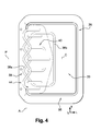
- the secondary rib 44 and the three additional ribs 46 of the front secondary plate 42 are each formed by stamping the main plate 34, and they are each convexly curved forward.
- the frame 26 comprises a rib 48 of "U” reinforcement, the contour of which follows that of the "U" -shaped light 36, as shown in FIG. figure 3 .
- the device 16 has an attached secondary secondary plate 50 which is fixed on a rear face 34b of the main plate 34, here by welding.
- the rear secondary plate 50 has a hinge secondary zone Z3 which extends along the axis of pivoting A of the flap 30, facing the hinge zone Z1 of the hinge 32, and which is able to be folded under the thrust force of the air bag 22.
- the rear secondary plate 50 is delimited by an edge 53 which extends transversely forming a coil and which runs along the outer edge of the first section 38a of the main rib 38, in order to reinforce the hinge 32.
- the rear secondary plate 50 has three reinforcing bosses 51 each of which is concave-shaped convex rearward.
- the main plate 34, the front secondary plate 42 and the rear secondary plate 50 are interconnected and traversed by four nail-shaped fixing pins 54, each of which extends generally parallel to the deployment axis B, in order to prevent the plates from slipping relative to each other when folding the hinge 32.
- each pin 54 has a rear free end which is fixed in the frame 24, for example in the manner of a rivet, so as to fix the assembly constituted by the plates on the frame 24.
- the device 16 includes a plurality of additional securing pins (not shown), which fix the frame 26 on the frame 24
- the air bag 22 is deployed forwardly along its deployment axis B, from its initial position folded in the module 18.
- the inflatable bag 22 exerts a thrust force on the flap 30, producing the folding of the hinge 32 so that the flap 30 is pivotally driven about its axis. pivoting A, from its closed position of rest to its open position.
- the pivoting of the shutter 30 causes the skin 14 to break from the dashboard 10.
- the rear face 14b of the skin 14 is pre-weakened by a notch 52 which extends "U" coincidentally with the "U" -shaped light 36 of the main plate 34.
- the various ribs 38, 40, 44, 46 oppose the pivoting of the flap 30 so as to brake the flap 30 during its pivoting.
- the pivoting speed of the flap 30 is such that the flap 30 damages little or no elements with which it is likely to come into contact.
- the flap 30 and the frame 26 are made integrally by plastic molding, in one piece.
- the reinforcing ribs may be metal inserts which are embedded in the shutter 30 during molding.
- first serpentine main rib 38 and the serpentine secondary rib 44 can be made in the same main plate 34.
- the hinge connecting the flap 30 to the frame 26 may be a reported hinge.
Landscapes
- Engineering & Computer Science (AREA)
- Mechanical Engineering (AREA)
- Air Bags (AREA)
Applications Claiming Priority (1)
| Application Number | Priority Date | Filing Date | Title |
|---|---|---|---|
| FR0758557A FR2922839B1 (fr) | 2007-10-25 | 2007-10-25 | Dispositif de securite a sec gonflable pour vehicule automobile. |
Publications (1)
| Publication Number | Publication Date |
|---|---|
| EP2052919A1 true EP2052919A1 (de) | 2009-04-29 |
Family
ID=39322925
Family Applications (1)
| Application Number | Title | Priority Date | Filing Date |
|---|---|---|---|
| EP08305682A Withdrawn EP2052919A1 (de) | 2007-10-25 | 2008-10-14 | Sicherheitsvorrichtung mit Airbag für Kraftfahrzeug |
Country Status (2)
| Country | Link |
|---|---|
| EP (1) | EP2052919A1 (de) |
| FR (1) | FR2922839B1 (de) |
Cited By (7)
| Publication number | Priority date | Publication date | Assignee | Title |
|---|---|---|---|---|
| WO1990003711A1 (de) * | 1988-09-26 | 1990-04-05 | E W D Electronic-Werke Deutschland Gmbh | Lautsprecher |
| FR2941193A1 (fr) * | 2009-01-21 | 2010-07-23 | Faurecia Interieur Ind | Agencement pour coussin de securite gonflable equipant une planche de bord de vehicule automobile |
| WO2012013341A1 (de) * | 2010-07-27 | 2012-02-02 | Johnson Controls Interiors Gmbh & Co. Kg | Vorrichtung für den airbag eines kraftfahrzeugs und armaturentafel |
| FR2976878A1 (fr) * | 2011-06-21 | 2012-12-28 | Faurecia Interieur Ind | Dispositif d'obturation de passage d'un coussin gonflable de vehicule automobile |
| WO2013029240A1 (en) | 2011-08-30 | 2013-03-07 | Faurecia (Shanghai) Management Company, Ltd | Trim assembly for covering airbag |
| US10377336B2 (en) * | 2017-11-13 | 2019-08-13 | Ford Global Technologies, Llc | Molded air bag chute with door reinforced by hollow channel |
| WO2025202396A1 (en) * | 2024-03-27 | 2025-10-02 | Autoliv Development Ab | Airbag cover |
Citations (5)
| Publication number | Priority date | Publication date | Assignee | Title |
|---|---|---|---|---|
| DE19930382A1 (de) * | 1998-07-09 | 2000-01-13 | Winget Larry J | Kraftfahrzeug-Instrumentenplatte mit integrierter angelenkter Airbag-Klappe |
| US6070901A (en) | 1998-10-19 | 2000-06-06 | Ford Global Technologies, Inc. | Automotive instrument panel having an integral airbag |
| EP1431134A2 (de) * | 2002-12-10 | 2004-06-23 | Calsonic Kansei Corporation | Tür einer Airbageinrichtung für Fahrzeug |
| FR2855806A1 (fr) * | 2003-06-05 | 2004-12-10 | Visteon Global Tech Inc | Dispositif d'articulation formant charniere avec limitation de mouvement et arrangement de coussin gonflable le comprenant |
| DE102005017124A1 (de) * | 2005-04-14 | 2006-10-19 | Volkswagen Ag | Verkleidungsteil für ein Fahrzeug, insbesondere für ein Kraftfahrzeug |
-
2007
- 2007-10-25 FR FR0758557A patent/FR2922839B1/fr active Active
-
2008
- 2008-10-14 EP EP08305682A patent/EP2052919A1/de not_active Withdrawn
Patent Citations (5)
| Publication number | Priority date | Publication date | Assignee | Title |
|---|---|---|---|---|
| DE19930382A1 (de) * | 1998-07-09 | 2000-01-13 | Winget Larry J | Kraftfahrzeug-Instrumentenplatte mit integrierter angelenkter Airbag-Klappe |
| US6070901A (en) | 1998-10-19 | 2000-06-06 | Ford Global Technologies, Inc. | Automotive instrument panel having an integral airbag |
| EP1431134A2 (de) * | 2002-12-10 | 2004-06-23 | Calsonic Kansei Corporation | Tür einer Airbageinrichtung für Fahrzeug |
| FR2855806A1 (fr) * | 2003-06-05 | 2004-12-10 | Visteon Global Tech Inc | Dispositif d'articulation formant charniere avec limitation de mouvement et arrangement de coussin gonflable le comprenant |
| DE102005017124A1 (de) * | 2005-04-14 | 2006-10-19 | Volkswagen Ag | Verkleidungsteil für ein Fahrzeug, insbesondere für ein Kraftfahrzeug |
Cited By (9)
| Publication number | Priority date | Publication date | Assignee | Title |
|---|---|---|---|---|
| WO1990003711A1 (de) * | 1988-09-26 | 1990-04-05 | E W D Electronic-Werke Deutschland Gmbh | Lautsprecher |
| FR2941193A1 (fr) * | 2009-01-21 | 2010-07-23 | Faurecia Interieur Ind | Agencement pour coussin de securite gonflable equipant une planche de bord de vehicule automobile |
| WO2012013341A1 (de) * | 2010-07-27 | 2012-02-02 | Johnson Controls Interiors Gmbh & Co. Kg | Vorrichtung für den airbag eines kraftfahrzeugs und armaturentafel |
| FR2976878A1 (fr) * | 2011-06-21 | 2012-12-28 | Faurecia Interieur Ind | Dispositif d'obturation de passage d'un coussin gonflable de vehicule automobile |
| WO2013029240A1 (en) | 2011-08-30 | 2013-03-07 | Faurecia (Shanghai) Management Company, Ltd | Trim assembly for covering airbag |
| CN103764452A (zh) * | 2011-08-30 | 2014-04-30 | 佛吉亚(上海)管理有限公司 | 用于覆盖安全气囊的饰板组件 |
| EP2750936A4 (de) * | 2011-08-30 | 2015-07-29 | Faurecia China Holding Co Ltd | Zierleiste für airbagabdeckung |
| US10377336B2 (en) * | 2017-11-13 | 2019-08-13 | Ford Global Technologies, Llc | Molded air bag chute with door reinforced by hollow channel |
| WO2025202396A1 (en) * | 2024-03-27 | 2025-10-02 | Autoliv Development Ab | Airbag cover |
Also Published As
| Publication number | Publication date |
|---|---|
| FR2922839B1 (fr) | 2010-02-26 |
| FR2922839A1 (fr) | 2009-05-01 |
Similar Documents
| Publication | Publication Date | Title |
|---|---|---|
| EP1514768B1 (de) | Gebrauchsverfahren fur einem Kotflügel und eine Motorhaube, mit einem Luftkissen und einem Kotflügel Stutz , Kfz-Kotflügel, Kfz-Kotflügelmodul, und Kfz-Motorhaube | |
| EP1283135B1 (de) | Luftkissen für ein Kraftfahrzeug | |
| EP0529389B1 (de) | Sicherheitseinrichtung in Form eines Gaskissens für Kraftfahrzeug | |
| EP2052919A1 (de) | Sicherheitsvorrichtung mit Airbag für Kraftfahrzeug | |
| EP2193052B1 (de) | Airbag-sicherheitsvorrichtung für ein kraftfahrzeug | |
| FR2479116A1 (fr) | Dispositif monte dans des vehicules automobiles pour la retenue de poches a air servant a proteger les passagers dudit vehicule | |
| FR2925410A1 (fr) | Planche de bord amelioree | |
| EP0953484B1 (de) | Seitenairbagmodul- Montagevorrichtung für einen Vordersitz eines Kraftfahrzeuges | |
| FR2761941A1 (fr) | Siege de vehicule dote d'un sac de securite gonflable lateral | |
| EP0819587A1 (de) | Luftsackmodul-Anordnung in einem Fahrzeugsitz | |
| EP1358084B1 (de) | Heckklappe eines personenkraftwagens mit stossfänger | |
| FR3106115A1 (fr) | Dispositif de sécurité de volant de véhicule | |
| EP1210252A1 (de) | Hilfsvorrichtung zum öffnen eines kraftfahrzeuggaskissens | |
| FR3089178A1 (fr) | Module de face avant pour véhicule automobile | |
| EP1100698B1 (de) | Airbaganordnung zum kraftfahrzeuginsassenschutz bei seitenaufprall | |
| EP0861761B1 (de) | Auswechselbares Airbagmodul für einen Kraftfahrzeugssitz | |
| FR2818706A1 (fr) | Dispositif de fixation securise pour la fixation d'accessoires sur un vehicule | |
| FR2941193A1 (fr) | Agencement pour coussin de securite gonflable equipant une planche de bord de vehicule automobile | |
| FR2782302A1 (fr) | Planche de bord equipee d'un coussin gonflable de securite dispose dans un boitier | |
| EP1669261B1 (de) | Kraftfahrzeugmotorhaube, ausgestattet mit Schutzmitteln gegen einen Fussgängeraufprall | |
| FR3124454A1 (fr) | Dispositif de sécurité pour véhicule | |
| FR2703012A1 (fr) | Structure de revêtement d'un élément de structure, notamment pour véhicule automobile, dans lequel est intégré un module à sac gonflable. | |
| FR3104510A1 (fr) | Boitier à coussin gonflable, dispositif de sécurité et procédé de fabrication d’un tel dispositif | |
| FR3158687A1 (fr) | Ensemble pour planche de bord de véhicule automobile et véhicule automobile comprenant un tel ensemble | |
| FR3163333A1 (fr) | Airbag de véhicule automobile avec couvercle d’évent |
Legal Events
| Date | Code | Title | Description |
|---|---|---|---|
| PUAI | Public reference made under article 153(3) epc to a published international application that has entered the european phase |
Free format text: ORIGINAL CODE: 0009012 |
|
| AK | Designated contracting states |
Kind code of ref document: A1 Designated state(s): AT BE BG CH CY CZ DE DK EE ES FI FR GB GR HR HU IE IS IT LI LT LU LV MC MT NL NO PL PT RO SE SI SK TR |
|
| AX | Request for extension of the european patent |
Extension state: AL BA MK RS |
|
| 17P | Request for examination filed |
Effective date: 20090709 |
|
| GRAP | Despatch of communication of intention to grant a patent |
Free format text: ORIGINAL CODE: EPIDOSNIGR1 |
|
| RAP1 | Party data changed (applicant data changed or rights of an application transferred) |
Owner name: RENAULT S.A.S. |
|
| AKX | Designation fees paid |
Designated state(s): AT BE BG CH CY CZ DE DK EE ES FI FR GB GR HR HU IE IS IT LI LT LU LV MC MT NL NO PL PT RO SE SI SK TR |
|
| STAA | Information on the status of an ep patent application or granted ep patent |
Free format text: STATUS: THE APPLICATION IS DEEMED TO BE WITHDRAWN |
|
| 18D | Application deemed to be withdrawn |
Effective date: 20100330 |