EP2053016A1 - Dispositif et procédé pour manipuler un objet amovible d'un objet plus grand - Google Patents
Dispositif et procédé pour manipuler un objet amovible d'un objet plus grand Download PDFInfo
- Publication number
- EP2053016A1 EP2053016A1 EP07118990A EP07118990A EP2053016A1 EP 2053016 A1 EP2053016 A1 EP 2053016A1 EP 07118990 A EP07118990 A EP 07118990A EP 07118990 A EP07118990 A EP 07118990A EP 2053016 A1 EP2053016 A1 EP 2053016A1
- Authority
- EP
- European Patent Office
- Prior art keywords
- movement
- rotational direction
- removable
- gripper
- removable object
- Prior art date
- Legal status (The legal status is an assumption and is not a legal conclusion. Google has not performed a legal analysis and makes no representation as to the accuracy of the status listed.)
- Granted
Links
- 238000000034 method Methods 0.000 title claims description 31
- 238000001514 detection method Methods 0.000 claims abstract description 11
- 239000002828 fuel tank Substances 0.000 claims description 50
- 230000009471 action Effects 0.000 claims description 25
- 238000010276 construction Methods 0.000 claims description 10
- 239000000446 fuel Substances 0.000 claims description 9
- 230000003213 activating effect Effects 0.000 claims description 8
- 230000004044 response Effects 0.000 claims description 5
- 230000003287 optical effect Effects 0.000 description 18
- 239000000945 filler Substances 0.000 description 15
- 238000012545 processing Methods 0.000 description 6
- 238000004891 communication Methods 0.000 description 5
- 230000004913 activation Effects 0.000 description 3
- 230000008859 change Effects 0.000 description 3
- 230000007246 mechanism Effects 0.000 description 3
- 230000002730 additional effect Effects 0.000 description 2
- 230000006698 induction Effects 0.000 description 2
- 230000004308 accommodation Effects 0.000 description 1
- 230000000903 blocking effect Effects 0.000 description 1
- 238000004364 calculation method Methods 0.000 description 1
- 239000000969 carrier Substances 0.000 description 1
- 230000000295 complement effect Effects 0.000 description 1
- 238000011161 development Methods 0.000 description 1
- 230000004886 head movement Effects 0.000 description 1
- 239000004973 liquid crystal related substance Substances 0.000 description 1
- 238000005259 measurement Methods 0.000 description 1
- 238000012986 modification Methods 0.000 description 1
- 230000004048 modification Effects 0.000 description 1
- 238000003909 pattern recognition Methods 0.000 description 1
- 230000008569 process Effects 0.000 description 1
- 230000005855 radiation Effects 0.000 description 1
- 238000012546 transfer Methods 0.000 description 1
- 230000001960 triggered effect Effects 0.000 description 1
Images





Classifications
-
- B—PERFORMING OPERATIONS; TRANSPORTING
- B25—HAND TOOLS; PORTABLE POWER-DRIVEN TOOLS; MANIPULATORS
- B25J—MANIPULATORS; CHAMBERS PROVIDED WITH MANIPULATION DEVICES
- B25J15/00—Gripping heads and other end effectors
- B25J15/02—Gripping heads and other end effectors servo-actuated
- B25J15/0206—Gripping heads and other end effectors servo-actuated comprising articulated grippers
-
- B—PERFORMING OPERATIONS; TRANSPORTING
- B25—HAND TOOLS; PORTABLE POWER-DRIVEN TOOLS; MANIPULATORS
- B25J—MANIPULATORS; CHAMBERS PROVIDED WITH MANIPULATION DEVICES
- B25J11/00—Manipulators not otherwise provided for
-
- B—PERFORMING OPERATIONS; TRANSPORTING
- B67—OPENING, CLOSING OR CLEANING BOTTLES, JARS OR SIMILAR CONTAINERS; LIQUID HANDLING
- B67D—DISPENSING, DELIVERING OR TRANSFERRING LIQUIDS, NOT OTHERWISE PROVIDED FOR
- B67D7/00—Apparatus or devices for transferring liquids from bulk storage containers or reservoirs into vehicles or into portable containers, e.g. for retail sale purposes
- B67D7/04—Apparatus or devices for transferring liquids from bulk storage containers or reservoirs into vehicles or into portable containers, e.g. for retail sale purposes for transferring fuels, lubricants or mixed fuels and lubricants
- B67D7/0401—Apparatus or devices for transferring liquids from bulk storage containers or reservoirs into vehicles or into portable containers, e.g. for retail sale purposes for transferring fuels, lubricants or mixed fuels and lubricants arrangements for automatically fuelling vehicles, i.e. without human intervention
-
- B—PERFORMING OPERATIONS; TRANSPORTING
- B67—OPENING, CLOSING OR CLEANING BOTTLES, JARS OR SIMILAR CONTAINERS; LIQUID HANDLING
- B67D—DISPENSING, DELIVERING OR TRANSFERRING LIQUIDS, NOT OTHERWISE PROVIDED FOR
- B67D7/00—Apparatus or devices for transferring liquids from bulk storage containers or reservoirs into vehicles or into portable containers, e.g. for retail sale purposes
- B67D7/04—Apparatus or devices for transferring liquids from bulk storage containers or reservoirs into vehicles or into portable containers, e.g. for retail sale purposes for transferring fuels, lubricants or mixed fuels and lubricants
- B67D7/0401—Apparatus or devices for transferring liquids from bulk storage containers or reservoirs into vehicles or into portable containers, e.g. for retail sale purposes for transferring fuels, lubricants or mixed fuels and lubricants arrangements for automatically fuelling vehicles, i.e. without human intervention
- B67D2007/0403—Fuelling robots
- B67D2007/0405—Opening devices
- B67D2007/0415—Opening devices for filler caps
-
- B—PERFORMING OPERATIONS; TRANSPORTING
- B67—OPENING, CLOSING OR CLEANING BOTTLES, JARS OR SIMILAR CONTAINERS; LIQUID HANDLING
- B67D—DISPENSING, DELIVERING OR TRANSFERRING LIQUIDS, NOT OTHERWISE PROVIDED FOR
- B67D7/00—Apparatus or devices for transferring liquids from bulk storage containers or reservoirs into vehicles or into portable containers, e.g. for retail sale purposes
- B67D7/04—Apparatus or devices for transferring liquids from bulk storage containers or reservoirs into vehicles or into portable containers, e.g. for retail sale purposes for transferring fuels, lubricants or mixed fuels and lubricants
- B67D7/0401—Apparatus or devices for transferring liquids from bulk storage containers or reservoirs into vehicles or into portable containers, e.g. for retail sale purposes for transferring fuels, lubricants or mixed fuels and lubricants arrangements for automatically fuelling vehicles, i.e. without human intervention
- B67D2007/0403—Fuelling robots
- B67D2007/0417—Manipulator arms
Definitions
- the present invention relates to a device and a method for handling a removable object from a larger object.
- the removable object may be a filler cap of a fuel tank of a vehicle.
- a method and apparatus arranged for automatic refueling of vehicles like cars are known in the art, e.g. from American patents US5671786 and US6269848 .
- a refueling robot is used for refueling of vehicles, like cars.
- a robot head that carries a fuel filler tube is movable to enable it provide fuel to a vehicle fuel-tank pipe.
- the robot head carries an opening device for opening a fuel-tank cover plate. The positioning of the robot head can be effected in different ways.
- the robot head carries a transceiver and the vehicle carries a transponder.
- the transceiver is arranged to send a signal to the transponder.
- the transponder includes a code which is intended to be modulated on the signal transmitted by the transceiver.
- the transponder then reflects the modulated signal towards the transceiver.
- the modulated code on the modulated signal is decoded by the transceiver, and the code is used to access a robot head movement plan.
- the movement plan corresponds with that code and provides the robot head with a plan to move the fuel filler tube towards the fuel tank pipe for refueling.
- a transceiver and transponder combination instead of a transceiver and transponder combination, a combination of a visually readable (bar) code and an optical sensor is used.
- the optical sensor is arranged adjacent to the robot head and is adapted to optically detect the position of the fuel-tank flap of a vehicle.
- the optical sensor is further arranged to sense a code that is optically readable and is being carried by the vehicle. Based on the code, a movement plan can be provided.
- the robot head is guided to the fuel-tank flap of a vehicle, arranged to open the fuel-tank flap by means of an opening device, and effectively dock the refueling nozzle, either both or the latter in accordance with aforementioned movement plan, and, finally, arranged to carry out these movements in a reverse order when refueling has been completed.
- many fuel-tanks are covered with a filler-cap.
- the position of the filler cap may be known with respect to the fuel-tank flap.
- Many filler caps are provided with a rim though, and the orientation of this rim is unknown. Positioning of the robot arm to enable removal of such a filler cap by grabbing the rim of the filler cap may be difficult.
- Either optical techniques may be employed to recognize the orientation of the rim, before the filler cap can be grabbed, or, alternatively, several grabbing attempts may be undertaken with different grabbing orientations, which may lead to a process of trial-and-error. Both techniques are rather complex and may take a considerable amount of time.
- the invention provides a device for handling a removable object from a larger object, the removable object (being removable from the larger object by rotation of the removable object in a first rotational direction and being attachable to the larger object by rotating the removable object in a second rotational direction, the first rotational direction being opposite to the second rotational direction, the device comprising:
- the invention provides a vehicle refueling system comprising:
- the invention provides a method of handling a removable object from a larger object, the removable object having a rotation axis and being removable from the larger object by rotation of the removable object in a first rotational direction and being attachable to the larger object by rotating the removable object in a second rotational direction, the first rotational direction being opposite to the second rotational direction, the method comprising:
- the invention provides a computer readable medium comprising computer executable code, which, when loaded on a computer system, enables the computer system to control aforementioned method.
- Figure 1 schematically depicts a vehicle refueling system, e.g. cars.
- the system comprises a refueling station 1 provided with fuel, a refueling nozzle 5 connected to the refueling station 1, e.g. by means of a hose 3, a robot 7 arranged for carrying the refueling nozzle 5 and moving it in accordance with movement instructions, and a computer system 9 arranged to provide said movement instructions to said robot 7.
- the refueling station 1 and the refueling nozzle 5 may correspond to tanks and refueling nozzles widely used in present day fuel stations.
- the robot 7 is provided with a robot arm 11 that is moveable in at least three directions.
- the robot arm 11 is capable of accommodating a number of devices 13.
- the devices 13 include a refueling nozzle fetching and carrying device, a fuel-tank flap opening device, a filler-cap handling device, and an optical detector.
- the devices 13 may further include one or more devices selected from a group consisting of a receiver, a touch sensor and a laser distance measuring device. Operation of aforementioned devices will be discussed hereafter in more detail.
- the computer system 9 comprises at least a processor 101 and a memory 105. Further details with respect to embodiments of the at least one processor 101 and memory 105, as well as other components that may be present in the computer system, will be described with reference to Figure 9 .
- the vehicle refueling system depicted in Figure 1 may operate as follows. First, a vehicle is positioned within an area 15 that can be covered by the robot arm 11 of the robot 7.
- the optical detector e.g. a camera, is arranged to detect the position of the vehicle within the area 15.
- the optical detector is communicationally connected with the computer system 9. When the position of the vehicle is determined by means of the optical detector, position information is sent to the computer system 9.
- the vehicle may be provided with a transponder.
- the transponder is arranged to transmit a signal provided with transponder information.
- the transponder information may comprise information corresponding to the vehicle or, alternatively, to a driver of the vehicle.
- the robot 7 is provided with a receiver arranged to receive the signal transmitted by the transponder.
- the receiver is communicationally connected to the computer system 9.
- the transponder information provided in the received signal is then used by the computer system 9 to obtain data related to the vehicle positioned within the area 15, especially information related to the type of car and parameters related thereto like the type of fuel-flap, the type of filler cap, their position with respect to each other, the plane of the bodywork in which the fuel-tank flap is embedded with respect to a horizontal plane and the position of the fuel-tank flap on the vehicle.
- the computer system 9 may use the position information in combination with the transponder information to determine a position of the fuel-tank flap. If necessary, instructions may be given to the driver of the vehicle to position the fuel-tank flap within closer range of the robot. In such a case, new position information needs to be determined by means of optical detection with the optical detector.
- the robot 7 is instructed by the computer system 9 to fetch the correct refueling nozzle 3 with the refueling nozzle fetching and carrying device provided on the robot arm 11.
- the robot may know which refueling nozzle 3 to take from aforementioned transponder information.
- the transponder information may include data with respect to the plane of the fuel-tank flap, i.e. the angle of the vehicle's bodywork with respect to the road.
- the robot 7 may now position the optical detector in a plane perpendicular to the plane of the fuel-tank flap. The distance between the robot 7 and the fuel-tank flap may now be determined by means of the optical detector, for example in a way as described hereinafter.
- the optical detector includes a camera.
- the camera takes, at a first position, a first picture of an area of the vehicle in which the fuel-tank flap is embedded. Subsequently, the camera is moved in a specified direction along, towards or away from the vehicle to reach a second position. At the second position, a second picture of the same area is taken. Both pictures are sent to the computer system 9 in a way known to a person skilled in the art. The computer system 9 then employs suitable pattern recognition techniques, e.g. so-called template matching, to determine the position of the fuel-tank flap within the pictures. Additionally, by comparison of the first and second picture, a global position of the fuel-tank flap relative to the robot 9 can be determined.
- suitable pattern recognition techniques e.g. so-called template matching
- the optical detector may comprise a laser distance measuring device.
- the laser distance measuring device may be used to determine a distance towards the fuel-tank flap.
- a laser may be used to define the position of the fuel-tank flap, e.g. in a way as described in American patent US6269848 .
- the robot 7 may further comprise a touch sensor.
- the touch sensor is communicationally connected to the computer system 9.
- the touch sensor is arranged to abut the bodywork of the vehicle at at least three predicted locations, the at least three predicted locations being predicted by using the transponder information in combination with the information received by means of the camera and/or laser distance measuring device.
- the touch sensor is further arranged to scan in a predetermined fashion around each predicted location if the predicted location turns out to be incorrect. If the correct location is found, the difference between the correct location and the predicted location may be determined. Based on at least three locations determined in this way a more accurate plane and/or position of the fuel-tank flap may be calculated.
- the transponder information may include information with respect to the type of fuel-tank flap.
- the information with respect to the type of fuel-tank flap does not only include information with respect to its plane and position, but also includes information with respect to the opening direction of the fuel-tank flap, i.e. whether it opens to the left side, to the right side, etc.
- the computer system 9 is arranged to calculate route information which takes aforementioned information with respect to the type of fuel-tank flap into account.
- the route information as calculated by the computer system 9, when sent from the computer system towards the robot, enables the robot arm to perform movements required for opening the fuel flap. If necessary, additional measurements may be performed with the optical detector, e.g. by making additional pictures with a camera, to enable accurate calculation of aforementioned route information.
- the computer system 9 may further be arranged to calculate an attachment position for the fuel-tank flap opening device based on the determined position and plane of the fuel-tank flap at hand.
- the fuel-tank flap opening device provided on the robot arm is arranged to open the fuel-tank flap based on the route information and the attachment position calculated by the computer system 9.
- the fuel-tank flap opening device is mounted on a load-cell.
- the load cell served as a touch sensor at an earlier stage.
- the fuel-tank flap opening device may include a sucking cup.
- the fuel-tank flap opening device is arranged to open the fuel-tank flap by positioning the sucking cup at the attachment position and moving the sucking cup after attachment in such a direction that the fuel-tank flap opens.
- This movement may be a linear movement.
- the fuel tank opening of the vehicle is still covered by a filler-cap.
- the position of the filler-cap with respect to the fuel-tank flap may be present in the transponder information. Alternatively, its position may be determined by means of the optical detector, e.g. in a way similar as described before with respect to determining the position of the fuel-tank flap.
- the filler-cap is removed by means of the filler-cap handling device.
- a tank opening reference picture may be made of the absolute position of the tank opening. That is, the position of the tank opening with respect to the absolute position of the camera is determined, e.g. a fixed position with respect to a coordinate system with a predetermined origin.
- the robot 7 may now use data from the computer system 9, e.g. additional route information, to position the fetched refueling nozzle 3 in the tank opening in such a way that refueling may start.
- the refueling nozzle fetching and carrying device provided on the robot arm 11 may be arranged to control the refueling nozzle 3. If the refueling nozzle 3 is accurately positioned in the tank opening, the refueling nozzle fetching and carrying device provided on the robot arm 11 may pull the trigger of the refueling nozzle 3 to start refueling.
- the robot 7 When the fuel-tank of the vehicle is filled, the robot 7 removes the refueling nozzle 3 from the vehicle tank opening by means of the refueling nozzle fetching and carrying device provided on the robot arm 11 and may place the refueling nozzle 3 back in its original position within the vehicle refueling system.
- a tank opening shift picture may be made of the absolute position of the tank opening.
- the computer system 9 may be arranged to compare the tank opening reference picture and the tank opening shift picture, and calculate what the new position of the filler cap should be.
- the filler cap handling device which still holds the filler-cap of the vehicle, is moved towards the new position of the filler cap, and the filler cap is put back on the tank opening.
- the robot 7 closes the tank-flap, e.g. by means of the fuel-tank flap opening device.
- the driver may be informed that automatic refueling was successfully completed, and that he may continue his/her journey. Payment may be performed in any way as known in the art.
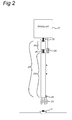
- Figure 2 schematically depicts an embodiment of a device for handling a removable object from a larger object.
- the device comprises a rotatable elongated element 20 having two ends. At a first end, the rotatable elongated element 20 is coupled to a driving unit 21 via a rotatable shaft 22. At a second end, the element 20 is provided with a gripper 23.
- the device for handling a removable object further comprises a sensing unit 25.
- the rotatable, elongated element 20 comprises two parts, i.e. a first part 20a and a second part 20b.
- the first part 20a is arranged for supporting connection of the rotatable axis 22 with the driving unit 21.
- the second part 20b comprises a cylindrical construction which is able to move with respect to the first part 20a.
- the first part 20a and second part 20b may be connected to each other by means of springs 26 or the like.
- the second part 20b is moveable with respect to the first part 20a in a direction along the rotatable shaft 22 by means of a slide construction. More details with respect to an embodiment of the slide construction are shown in and described with reference to Figure 6 . Consequently, the second part 20b can only be moved in a linear direction with respect to first part 20a. Rotational movement of the second part 20b with respect to the first part 20a is prevented by aforementioned slide construction.
- the removable object 27 has a rotation axis.
- the removable object 27 is removable from the larger object by rotation of the removable object in a first rotational direction.
- the removable object 27 is attachable to the larger object by rotating the removable object in a second rotational direction.
- the first rotational direction is opposite to the second rotational direction.
- the removable object 27 is a filler-cap of a fuel tank of a vehicle.
- the driving unit 21 is arranged for rotating the elongated element 20.
- the driving unit 21 may further be arranged to move the elongated element 20 in a first linear direction substantially parallel to the rotation axis of the removable object 27.
- the gripper also rotates and moves linearly respectively.
- the driving unit 21 comprises an electro-motor.
- the gripper 23 is arranged for gripping a removable object 27 from a larger object.
- the gripper 23 may be provided with at least two gripping units.
- the at least two gripping units are arranged with respect to each other to enable a gripping action.
- the sensing unit 25 is arranged for sensing a non-linear change of movement of the rotatable elongated element 20 in a direction parallel to the first linear direction.
- the sensing unit 25 is a light sensor.
- the light sensor is arranged such that depending on the position of the second part 20b of the elongated element 20 light is detected or not. More details with respect to a light sensor as sensing unit 25 is explained with reference to Figure 5 .
- the sensing unit 25 may comprise some type of sensor for sensing a force. In such a case, the connection between the first part 20a and the second part 20b may be such that a force can develop between them.
- the sensing unit 25 is then arranged to detect a rapid variation in that force.
- the device may further comprise a control unit 29.
- the control unit may be communicationally connected to the sensing unit 25.
- the sensing unit 25 is further arranged to generate a sensing signal indicating a movement of the second part 20b of the rotatable elongated element 20 with respect to the first part 20a thereof has been detected.
- the control unit 29 may be arranged for activating the gripper 23 in response to reception of aforementioned sensing signal.
- Figure 3 depicts a more detailed embodiment of a device 31 for handling a rotationally removable object, like a filler-cap, from a larger object.
- the device 31 is depicted while being in a first state.
- the gripper 23 is provided with at least two gripping units 33.
- the at least two gripping units 33 are arranged with respect to each other to enable a gripping action.
- the gripping units 33 are in an opening position, i.e. no gripping action is performed.
- the rotatable shaft 22 of the device 31 is arranged to be rotated by the driving unit (not shown) in the first rotational direction, i.e. the rotational direction of removal, while linearly moving the device 31 in a direction parallel to the rotatable shaft 22 of the device 31 towards the rotationally removable object 27, in Figure 3 a filler-cap 35 provided with a rib 37 which orientation is unknown.
- the orientation of the rotatable shaft 22 of the device 31 is substantially parallel to the rotation axis of the rotationally removable object 27. Additionally, the orientation of the rotatable shaft 22 of the device 31 may further be substantially perpendicular to the orientation of the surface of the rotationally removable object 27.
- the sensing unit 25 may be arranged to sense aforementioned development of a pressure force, e.g. by detecting movement in a sliding construction as mentioned earlier.
- Figure 4 depicts the device 31 for handling a rotationally removable object of Figure 3 in a second state.
- the at least two gripping units 33 are in a closing position, i.e. a gripping action is performed.
- the gripper 23 is activated.
- a force develops between the first part 20a and the second part 20b of the rotatable shaft 22 if the linear movement of the gripper 23 is blocked by the upper surface of the rim 37 of the filler-cap 35.
- the at least two gripping units 33 eventually obtain an orientation in which they no longer make contact with the upper surface of the rim 37.
- the sensing unit 25 may send a sensing signal towards the control unit 29.
- the control unit 29 upon receipt of said sensing signal, activates the gripper 23, i.e. a gripping action is performed by the gripping units 33 as they move from an opening position towards a closing position.
- the device 31 does not abut with the filler-cap 35 on top of the rib 37, but contacts the rib 37 later, the rotational movement of the rotatable shaft 22 will be blocked.
- the distance towards the fuel-tank is known.
- information regarding the size of the filler-cap may be provided in the transponder information. So, if the device 31 in its linear movement towards the filler-cap 35 passes the top surface of the rib 37 in view of the known distance towards the fuel-tank in combination with the known height of the filler-cap 35, the device 31 may be triggered to enable the gripping action if rotational movement is blocked. Finally, if the device 31 reaches the bottom surface of the filler-cap 35 before rotational movement is stopped, upon detection of a blocking of the linear movement due to abutment with the bottom surface of the filler-cap 35, a gripping action is performed.
- the gripping units 33 have a semi-circular shape. This shape enables the gripping units 33 to grab the sides of the rim 37, even if their orientation with respect to the rim 37 is less than optimal, when the gripping action is activated.
- FIGs 5a-5c schematically depict the operation of a sensing unit that may be used in embodiments of a device for handling a rotationally removable object.
- the sensing units comprises two components, a light source 41 and a light detector 43.
- the light source 41 is arranged to generate a light beam 45 in a direction towards the light detector 43.
- the light detector 43 is arranged to detect the light beam 45 emitted by the light source 41.
- the path of the light beam 45 between the light source 41 and light detector 43 crosses a space between the first part 20a and second part 20b of the rotatable elongated element 20.
- the rotatable axis 22, which is depicted in figures 2-4 is not shown to enhance the clarity of Figures 5a-c .
- the first part 20a and second part 20b are connected to each other by means of a flexible connecting unit 49 like a spring 26.
- the light source 41 may be connected to the robot arm, denoted in Figures 1 , 2 by reference number 11, or, alternatively, to the first part 20a of the rotatable elongated element 20.
- the light detector 43 may also be connected to the robot arm or the first part of the rotatable elongated element.
- Figure 5a represents a configuration of the first and second part 20a, 20b, the light source 41 and light detector 43 in case the rotatable elongated element is directed towards the removable object while rotating before the gripper makes contact with the removable object. In this case, the light generated by the light source 41 is detected by the light detector 43.
- the upper surface 37 blocks the linear movement of the rotatable elongated element and the second part 20b is pushed in a direction towards the first part 20a, a movement schematically depicted by the arrow in Figure 5b . Due to this movement energy is stored in the flexible connecting unit 49. Furthermore, the light beam 45 generated by the light source 41 is blocked by the second part 20b, and the detector 43 no longer detects the light beam 45. In an embodiment, the sensing unit 25, upon detecting that the light beam 45 is no longer detected alarms the control unit, e.g. control unit 29 in Figure 2 , to be ready for activation.
- the control unit e.g. control unit 29 in Figure 2
- a light sensor as sensing unit 25 may be used in embodiments of the device for handling a rotationally removable object according to the invention.
- the light source 41 may generate multiple light beams, each light beam configured to cross the space between the first and second part 20a, 20b of the rotatable elongated element 20 at a different "height" level. With such an arrangement, smaller movements of the second part 20b with respect to the first part 20a may be detected than would be possible in a single-beam embodiment.
- the light sensor may be arranged in such a way that the light beam 45 can only be detected by the detector 43 in case the second part 20b moves away from the first part 20a beyond the distance between the two in case no energy is stored in the flexible connecting element 49, i.e. in a situation schematically depicted in Figure 5c .
- embodiments of the invention may also use a different type of sensor as a sensing unit 25, e.g. a pressure sensor located between the first part 20a and second part 20b, a sensor operating in a similar way as the light sensor presented above but using a different type of radiation, a distance sensor like a capacitance sensor arranged to measure the distance between the first part 20a and the second part 20b, an induction sensor arranged to detect a change of position of the second part 20b due to detection of a change in induction current, etc.
- a different type of sensor e.g. a pressure sensor located between the first part 20a and second part 20b
- a sensor operating in a similar way as the light sensor presented above but using a different type of radiation e.g. a distance sensor located between the first part 20a and second part 20b
- a distance sensor like a capacitance sensor arranged to measure the distance between the first part 20a and the second part 20b
- an induction sensor arranged to detect a change of position of the second
- Figure 6 shows in more detail an embodiment of a sliding construction that enables a controlled movement of the second part 20b of the rotatable elongated element 20 with respect to the first part 20a thereof, in particular the movements schematically depicted by arrows in Figures 5b and 5c .
- a splined shaft is used as rotation shaft 22. That is, the rotation shaft 22 is divided in two parts, a first sub-part and a second sub-part.
- the first part of the splined shaft is connected to the first part 20a of the device.
- the second part of the splined shaft is integrated in the second part 20b of the device.
- the second part 20b comprises a hollow chamber in order to accommodate the first sub-part of the splined shaft.
- the first part of the rotation shaft 22 is provided with one or more extended structures 57, e.g. ridges.
- the inner surface of the hollow chamber of the second part of the device 20b is provided with one or more complementary recesses 58, e.g. slits or grooves.
- This arrangement of the first and second sub-parts of the rotation shaft 22 enable accommodation of one or more extended structures 57 of the first sub-part in such a way that the one or more extended structures 57 can be moved within one or more recesses 58 in the second sub-part such that a guided movement is established, while the first and second sub-parts do not rotate with respect to each other.
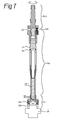
- Figure 7 depicts a cross-section of the device 31 for handling a rotationally removable object of Figures 3 and 4 .
- Figure 7 schematically shows the sliding construction as explained in more detail with reference to Figure 6 .
- Figure 7 schematically shows a control mechanism of the gripper 23.
- the control mechanism of the gripper 23 comprises a hollow chamber 51.
- a piston construction 53 is shown, which may control movement of a elongated structure 52.
- the elongated structure 52 is connected to the gripping units 33 via a pin 54 and one or more springs 55.
- aforementioned control mechanism may activate and deactivate the gripper 23 and control movement of the gripping units 33.
- Figure 8 schematically depicts an embodiment of a method for handling a removable object from a larger object.
- the method may be executed by software loaded in a computer system, e.g. computer system 9 depicted in Figure 1 .
- the software may be in the form of computer executable code stored on a computer readable medium which can be loaded on the computer system.
- the removable object is a filler-cap of a fuel-tank of a vehicle.
- embodiments of the device for handling a rotationally removable object e.g. embodiments shown in Figures 2-7 , may be used.
- the removable object is removable from a larger object. It has a rotation axis.
- the removable object is removable form the larger object by rotation of the removable object in a first rotation direction.
- the removable object may further be attachable to the larger object by rotating the removable object in a second rotational direction, the second rotational direction being opposite to the first rotational direction.
- the device for handling a removable object is moved towards the rotationally removable object in a first linear direction.
- the first linear direction corresponds to a direction towards the rotationally removable object, and is further substantially parallel to the rotation axis of the removable object.
- the device is rotating about its rotatable shaft in the second rotational direction.
- action 63 detection of a movement of the second part of the rotatable elongated object with respect to the first part thereof is activated for a predetermined period of time.
- the predetermined period of time is related to the distance between the device and the removable object when starting action 61. It corresponds to the time that is needed to transfer the device across aforementioned distance at the movement velocity of the device in the first linear direction.
- the gripper In response to detecting a certain type of movement, in action 65, the gripper is activated. This results in the device performing a gripping action as is explained with reference to Figures 3-7 . If no certain type of movement has been detected within the predetermined period of time, i.e. the device has reached the surface of the larger object, the gripping action is performed after the predetermined period of time has lapsed.
- the device is moved in a second linear direction, the second linear direction being substantially opposite to the first linear direction. Simultaneously the device is rotated about its rotatable shaft in the first rotational direction.
- the method further includes, in action 71, determining removal of the rotationally removable object, and, subsequently in action 73, stopping the rotation in the first rotational direction while continuing the movement in the second linear direction. The movement in the second linear direction may then be stopped when the removed rotationally removable object has reached a certain position.
- determining removal of the rotationally removable object is performed by counting a predetermined number of rotations in said first rotational direction. The number of rotations needed to remove the removable object may be part of transponder information obtained in a way as described earlier with reference to Figure 1 . Please note that the gripping action is firm enough to ensure that the filler-cap is not dropped after removal.
- the method may further comprise an additional action, between actions 65 and 67, i.e. activating the gripper and stopping the moving and rotating of the device respectively.
- this additional action i.e. action 75
- the device is rotated in the second rotational direction during a further predetermined period of time.
- this further predetermined period of time will be limited, i.e. enough to ensure that the removable object is attached sufficiently to the larger object.
- the additional rotational movement in the second rotational direction may ensure that the gripping units are well in place, before starting subsequent actions.
- Figure 9 shows an embodiment of a computer system 100 that may be used in a vehicle refueling system, e.g.
- the computer system 100 may be arranged to control the movements of a driving unit, e.g. driving unit 21, responsible for the rotation and moving of the rotatable axis of the device for handling a rotationally removable object, e.g. according to the method described with reference to Figure 7 .
- the computer system 100 may be arranged for loading a computer readable medium comprising computer executable code. This may enable the computer system 100 to execute, when the computer executable code on the computer readable medium is loaded, embodiments of aforementioned method of handling a removable object from a larger object.
- the computer system 100 comprises a processor 101 and a memory 105.
- the memory 105 which is connected to the processor 101, may comprise a number of memory components like a hard disk 111, Read Only Memory (ROM) 112, Electrically Erasable Programmable Read Only Memory (EEPROM) 113 en Random Access Memory (RAM) 114. Not all aforementioned memory components need to be present. Furthermore, it is not essential that aforementioned memory components are physically in close proximity to the processor 101 or to each other. They may be located at a distance away
- the processor 101 may also be connected to some kind of user interface, for instance a keyboard 115 or a mouse 116.
- a keyboard 115 or a mouse 116 may also be connected to some kind of user interface.
- a touch screen, track ball, speech converter or other interfaces that are known to persons skilled in the art may also be used.
- the processor 101 may be connected to a reading unit 117, which is arranged to read data from and under some circumstances store data on a data carrier, like a floppy disc 118 or a CDROM 119. Also DVD's or other data carriers known to persons skilled in the art may be used.
- a reading unit 117 which is arranged to read data from and under some circumstances store data on a data carrier, like a floppy disc 118 or a CDROM 119. Also DVD's or other data carriers known to persons skilled in the art may be used.
- the processor 101 may also be connected to a printer 120 to print out output data on paper as well as to a display 121, for instance a monitor or LCD (Liquid Crystal Display), of any other type of display known to a person skilled in the art.
- a printer 120 to print out output data on paper as well as to a display 121, for instance a monitor or LCD (Liquid Crystal Display), of any other type of display known to a person skilled in the art.
- LCD Liquid Crystal Display
- the processor 101 may be connected to a communications network 122, for instance a public switched telephone network (PSTN), a local area network (LAN), a wide area network (WAN) etc. by means of transmitters/receivers 123 responsible for input/output (I/O).
- the processor 101 may be arranged to communicate with other communication systems via the communications network 122.
- external computers (not shown), for instance personal computers of operators, can log into the processor 101 via the communications network 122.
- the processor 101 may be implemented as an independent system or as a number of processing units that operate in parallel, wherein each processing unit is arranged to execute sub-tasks of a larger program.
- the processing units may also be divided in one or more main processing units with several subprocessing units. Some processing units of the processor 101 may even be located a distance away of the other processing units and communicate via communications network 122.
Landscapes
- Engineering & Computer Science (AREA)
- Mechanical Engineering (AREA)
- Robotics (AREA)
- Manipulator (AREA)
- Loading And Unloading Of Fuel Tanks Or Ships (AREA)
- Supplying Of Containers To The Packaging Station (AREA)
- Auxiliary Devices For And Details Of Packaging Control (AREA)
- Load-Engaging Elements For Cranes (AREA)
Priority Applications (3)
| Application Number | Priority Date | Filing Date | Title |
|---|---|---|---|
| AT07118990T ATE490944T1 (de) | 2007-10-22 | 2007-10-22 | VORRICHTUNG UND VERFAHREN ZUR HANDHABUNG EINES VON EINEM GRÖßEREN OBJEKT ABNEHMBAREN OBJEKTS |
| DE602007011076T DE602007011076D1 (de) | 2007-10-22 | 2007-10-22 | Vorrichtung und Verfahren zur Handhabung eines von einem größeren Objekt abnehmbaren Objekts |
| EP07118990A EP2053016B1 (fr) | 2007-10-22 | 2007-10-22 | Dispositif et procédé pour manipuler un objet amovible d'un objet plus grand |
Applications Claiming Priority (1)
| Application Number | Priority Date | Filing Date | Title |
|---|---|---|---|
| EP07118990A EP2053016B1 (fr) | 2007-10-22 | 2007-10-22 | Dispositif et procédé pour manipuler un objet amovible d'un objet plus grand |
Publications (2)
| Publication Number | Publication Date |
|---|---|
| EP2053016A1 true EP2053016A1 (fr) | 2009-04-29 |
| EP2053016B1 EP2053016B1 (fr) | 2010-12-08 |
Family
ID=39271190
Family Applications (1)
| Application Number | Title | Priority Date | Filing Date |
|---|---|---|---|
| EP07118990A Not-in-force EP2053016B1 (fr) | 2007-10-22 | 2007-10-22 | Dispositif et procédé pour manipuler un objet amovible d'un objet plus grand |
Country Status (3)
| Country | Link |
|---|---|
| EP (1) | EP2053016B1 (fr) |
| AT (1) | ATE490944T1 (fr) |
| DE (1) | DE602007011076D1 (fr) |
Cited By (4)
| Publication number | Priority date | Publication date | Assignee | Title |
|---|---|---|---|---|
| CN107150994A (zh) * | 2017-04-28 | 2017-09-12 | 西安交通大学 | 一种用于汽车加油机器人的末端执行器 |
| CN109895645A (zh) * | 2019-03-29 | 2019-06-18 | 南京理工大学 | 一种新能源汽车自动充电系统 |
| WO2020173518A1 (fr) * | 2019-02-25 | 2020-09-03 | Dürr Somac GmbH | Outil de vissage servant à manipuler des éléments de fermeture sur des contenants de véhicule servant à recevoir des carburants |
| CN111633408A (zh) * | 2020-05-26 | 2020-09-08 | 杭州魔象智能科技有限公司 | 一种汽车油箱盖开盖结构 |
Families Citing this family (1)
| Publication number | Priority date | Publication date | Assignee | Title |
|---|---|---|---|---|
| DE102015225989B3 (de) * | 2015-12-18 | 2017-05-18 | Kuka Roboter Gmbh | Verfahren zur Durchführung wenigstens eines Energieversorgungsvorgangs zwischen einer Energieversorgungseinheit und wenigstens einem mit Energie zu versorgenden Kraftfahrzeug |
Citations (3)
| Publication number | Priority date | Publication date | Assignee | Title |
|---|---|---|---|---|
| US3527268A (en) * | 1967-07-26 | 1970-09-08 | Standard Oil Co | Device for automatically filling vehicle tanks with motor fuel |
| US3773189A (en) * | 1971-10-13 | 1973-11-20 | Y Kitamura | Pneumatically powered loading unit for use with an industrial robot |
| WO1994003391A1 (fr) * | 1992-07-31 | 1994-02-17 | Gian Carlo Brazzelli | Poste d'essence automatique |
-
2007
- 2007-10-22 AT AT07118990T patent/ATE490944T1/de not_active IP Right Cessation
- 2007-10-22 EP EP07118990A patent/EP2053016B1/fr not_active Not-in-force
- 2007-10-22 DE DE602007011076T patent/DE602007011076D1/de active Active
Patent Citations (3)
| Publication number | Priority date | Publication date | Assignee | Title |
|---|---|---|---|---|
| US3527268A (en) * | 1967-07-26 | 1970-09-08 | Standard Oil Co | Device for automatically filling vehicle tanks with motor fuel |
| US3773189A (en) * | 1971-10-13 | 1973-11-20 | Y Kitamura | Pneumatically powered loading unit for use with an industrial robot |
| WO1994003391A1 (fr) * | 1992-07-31 | 1994-02-17 | Gian Carlo Brazzelli | Poste d'essence automatique |
Cited By (5)
| Publication number | Priority date | Publication date | Assignee | Title |
|---|---|---|---|---|
| CN107150994A (zh) * | 2017-04-28 | 2017-09-12 | 西安交通大学 | 一种用于汽车加油机器人的末端执行器 |
| WO2020173518A1 (fr) * | 2019-02-25 | 2020-09-03 | Dürr Somac GmbH | Outil de vissage servant à manipuler des éléments de fermeture sur des contenants de véhicule servant à recevoir des carburants |
| US11865694B2 (en) | 2019-02-25 | 2024-01-09 | Dürr Somac GmbH | Rotary driving tool for handling closure elements |
| CN109895645A (zh) * | 2019-03-29 | 2019-06-18 | 南京理工大学 | 一种新能源汽车自动充电系统 |
| CN111633408A (zh) * | 2020-05-26 | 2020-09-08 | 杭州魔象智能科技有限公司 | 一种汽车油箱盖开盖结构 |
Also Published As
| Publication number | Publication date |
|---|---|
| ATE490944T1 (de) | 2010-12-15 |
| EP2053016B1 (fr) | 2010-12-08 |
| DE602007011076D1 (de) | 2011-01-20 |
Similar Documents
| Publication | Publication Date | Title |
|---|---|---|
| EP2053015B1 (fr) | Buse de ravitaillement en carburant et système automatique de ravitaillement en carburant l'utilisant | |
| EP2053016B1 (fr) | Dispositif et procédé pour manipuler un objet amovible d'un objet plus grand | |
| US11548730B2 (en) | Refuse vehicle dump verification system and apparatus | |
| EP2707725B1 (fr) | Élément de transport de produits de laboratoire et agencement pour trajet | |
| SE515352C2 (sv) | Kopplingsanordning för en passagerarbrygga | |
| US20120158222A1 (en) | Centering above a predetermined area of a landing platform | |
| JP6542318B2 (ja) | ホームドア制御装置及びホームドア制御方法 | |
| CN113424125A (zh) | 移动机器人、移动机器人的控制系统、移动机器人的控制方法 | |
| JP4283897B2 (ja) | 車両の自動給油における位置決め装置 | |
| KR102083129B1 (ko) | 자기 위치 추종 기능을 가진 배관 내부 검사용 주행체 | |
| JP5193879B2 (ja) | 自動車のドア閉まり検査装置及び検査方法 | |
| US6269848B1 (en) | Device for automatic fuelling of vehicles | |
| EP3588010B1 (fr) | Procédé pour valider des données d'étalonnage d'au moins une unité de détection d'un véhicule, dispositif d'entretien de véhicule correspondant et système d'entretien | |
| US20240151512A1 (en) | System for automated surveying of motor vehicles | |
| KR102029584B1 (ko) | 차량의 도어를 제어하기 위한 장치, 이를 위한 방법 및 이 방법을 수행하는 프로그램이 기록된 컴퓨터 판독 가능한 기록매체 | |
| JP6502107B2 (ja) | ホームドア制御装置及びホームドア制御方法 | |
| US11565931B2 (en) | Beverage dispenser | |
| CN102445150A (zh) | 用于冶金容器浇口的自动位置识别的方法和测量装置 | |
| JP2024147889A (ja) | 荷役システム及び荷役方法 | |
| CN109835252A (zh) | 车辆后向倒车碰撞预警系统 | |
| TWI916673B (zh) | 提取系統及用以操作提取系統的方法 | |
| US12498732B2 (en) | Systems and methods for characterizing a vehicle motion of an autonomous mobile robot | |
| JP2704918B2 (ja) | 船舶用荷役機械の制御装置 | |
| CN115268372A (zh) | 移动井盖的控制方法和系统 | |
| US12545568B2 (en) | Dispensing system and method of operating a dispensing system |
Legal Events
| Date | Code | Title | Description |
|---|---|---|---|
| PUAI | Public reference made under article 153(3) epc to a published international application that has entered the european phase |
Free format text: ORIGINAL CODE: 0009012 |
|
| AK | Designated contracting states |
Kind code of ref document: A1 Designated state(s): AT BE BG CH CY CZ DE DK EE ES FI FR GB GR HU IE IS IT LI LT LU LV MC MT NL PL PT RO SE SI SK TR |
|
| AX | Request for extension of the european patent |
Extension state: AL BA HR MK RS |
|
| 17P | Request for examination filed |
Effective date: 20091022 |
|
| AKX | Designation fees paid |
Designated state(s): AT BE BG CH CY CZ DE DK EE ES FI FR GB GR HU IE IS IT LI LT LU LV MC MT NL PL PT RO SE SI SK TR |
|
| GRAP | Despatch of communication of intention to grant a patent |
Free format text: ORIGINAL CODE: EPIDOSNIGR1 |
|
| RIC1 | Information provided on ipc code assigned before grant |
Ipc: B67D 7/04 20100101AFI20100429BHEP |
|
| GRAS | Grant fee paid |
Free format text: ORIGINAL CODE: EPIDOSNIGR3 |
|
| GRAA | (expected) grant |
Free format text: ORIGINAL CODE: 0009210 |
|
| AK | Designated contracting states |
Kind code of ref document: B1 Designated state(s): AT BE BG CH CY CZ DE DK EE ES FI FR GB GR HU IE IS IT LI LT LU LV MC MT NL PL PT RO SE SI SK TR |
|
| REG | Reference to a national code |
Ref country code: GB Ref legal event code: FG4D |
|
| REG | Reference to a national code |
Ref country code: CH Ref legal event code: EP |
|
| REG | Reference to a national code |
Ref country code: IE Ref legal event code: FG4D |
|
| REF | Corresponds to: |
Ref document number: 602007011076 Country of ref document: DE Date of ref document: 20110120 Kind code of ref document: P |
|
| REG | Reference to a national code |
Ref country code: NL Ref legal event code: T3 |
|
| PG25 | Lapsed in a contracting state [announced via postgrant information from national office to epo] |
Ref country code: LT Free format text: LAPSE BECAUSE OF FAILURE TO SUBMIT A TRANSLATION OF THE DESCRIPTION OR TO PAY THE FEE WITHIN THE PRESCRIBED TIME-LIMIT Effective date: 20101208 |
|
| LTIE | Lt: invalidation of european patent or patent extension |
Effective date: 20101208 |
|
| PG25 | Lapsed in a contracting state [announced via postgrant information from national office to epo] |
Ref country code: SE Free format text: LAPSE BECAUSE OF FAILURE TO SUBMIT A TRANSLATION OF THE DESCRIPTION OR TO PAY THE FEE WITHIN THE PRESCRIBED TIME-LIMIT Effective date: 20101208 Ref country code: FI Free format text: LAPSE BECAUSE OF FAILURE TO SUBMIT A TRANSLATION OF THE DESCRIPTION OR TO PAY THE FEE WITHIN THE PRESCRIBED TIME-LIMIT Effective date: 20101208 Ref country code: LV Free format text: LAPSE BECAUSE OF FAILURE TO SUBMIT A TRANSLATION OF THE DESCRIPTION OR TO PAY THE FEE WITHIN THE PRESCRIBED TIME-LIMIT Effective date: 20101208 Ref country code: SI Free format text: LAPSE BECAUSE OF FAILURE TO SUBMIT A TRANSLATION OF THE DESCRIPTION OR TO PAY THE FEE WITHIN THE PRESCRIBED TIME-LIMIT Effective date: 20101208 Ref country code: BG Free format text: LAPSE BECAUSE OF FAILURE TO SUBMIT A TRANSLATION OF THE DESCRIPTION OR TO PAY THE FEE WITHIN THE PRESCRIBED TIME-LIMIT Effective date: 20110308 Ref country code: CY Free format text: LAPSE BECAUSE OF FAILURE TO SUBMIT A TRANSLATION OF THE DESCRIPTION OR TO PAY THE FEE WITHIN THE PRESCRIBED TIME-LIMIT Effective date: 20101208 Ref country code: AT Free format text: LAPSE BECAUSE OF FAILURE TO SUBMIT A TRANSLATION OF THE DESCRIPTION OR TO PAY THE FEE WITHIN THE PRESCRIBED TIME-LIMIT Effective date: 20101208 |
|
| PG25 | Lapsed in a contracting state [announced via postgrant information from national office to epo] |
Ref country code: IS Free format text: LAPSE BECAUSE OF FAILURE TO SUBMIT A TRANSLATION OF THE DESCRIPTION OR TO PAY THE FEE WITHIN THE PRESCRIBED TIME-LIMIT Effective date: 20110408 Ref country code: CZ Free format text: LAPSE BECAUSE OF FAILURE TO SUBMIT A TRANSLATION OF THE DESCRIPTION OR TO PAY THE FEE WITHIN THE PRESCRIBED TIME-LIMIT Effective date: 20101208 Ref country code: PT Free format text: LAPSE BECAUSE OF FAILURE TO SUBMIT A TRANSLATION OF THE DESCRIPTION OR TO PAY THE FEE WITHIN THE PRESCRIBED TIME-LIMIT Effective date: 20110408 Ref country code: EE Free format text: LAPSE BECAUSE OF FAILURE TO SUBMIT A TRANSLATION OF THE DESCRIPTION OR TO PAY THE FEE WITHIN THE PRESCRIBED TIME-LIMIT Effective date: 20101208 Ref country code: ES Free format text: LAPSE BECAUSE OF FAILURE TO SUBMIT A TRANSLATION OF THE DESCRIPTION OR TO PAY THE FEE WITHIN THE PRESCRIBED TIME-LIMIT Effective date: 20110319 Ref country code: BE Free format text: LAPSE BECAUSE OF FAILURE TO SUBMIT A TRANSLATION OF THE DESCRIPTION OR TO PAY THE FEE WITHIN THE PRESCRIBED TIME-LIMIT Effective date: 20101208 Ref country code: GR Free format text: LAPSE BECAUSE OF FAILURE TO SUBMIT A TRANSLATION OF THE DESCRIPTION OR TO PAY THE FEE WITHIN THE PRESCRIBED TIME-LIMIT Effective date: 20110309 |
|
| PG25 | Lapsed in a contracting state [announced via postgrant information from national office to epo] |
Ref country code: PL Free format text: LAPSE BECAUSE OF FAILURE TO SUBMIT A TRANSLATION OF THE DESCRIPTION OR TO PAY THE FEE WITHIN THE PRESCRIBED TIME-LIMIT Effective date: 20101208 Ref country code: SK Free format text: LAPSE BECAUSE OF FAILURE TO SUBMIT A TRANSLATION OF THE DESCRIPTION OR TO PAY THE FEE WITHIN THE PRESCRIBED TIME-LIMIT Effective date: 20101208 Ref country code: RO Free format text: LAPSE BECAUSE OF FAILURE TO SUBMIT A TRANSLATION OF THE DESCRIPTION OR TO PAY THE FEE WITHIN THE PRESCRIBED TIME-LIMIT Effective date: 20101208 |
|
| PLBE | No opposition filed within time limit |
Free format text: ORIGINAL CODE: 0009261 |
|
| STAA | Information on the status of an ep patent application or granted ep patent |
Free format text: STATUS: NO OPPOSITION FILED WITHIN TIME LIMIT |
|
| PG25 | Lapsed in a contracting state [announced via postgrant information from national office to epo] |
Ref country code: DK Free format text: LAPSE BECAUSE OF FAILURE TO SUBMIT A TRANSLATION OF THE DESCRIPTION OR TO PAY THE FEE WITHIN THE PRESCRIBED TIME-LIMIT Effective date: 20101208 |
|
| 26N | No opposition filed |
Effective date: 20110909 |
|
| PG25 | Lapsed in a contracting state [announced via postgrant information from national office to epo] |
Ref country code: IT Free format text: LAPSE BECAUSE OF FAILURE TO SUBMIT A TRANSLATION OF THE DESCRIPTION OR TO PAY THE FEE WITHIN THE PRESCRIBED TIME-LIMIT Effective date: 20101208 |
|
| REG | Reference to a national code |
Ref country code: DE Ref legal event code: R097 Ref document number: 602007011076 Country of ref document: DE Effective date: 20110909 |
|
| PGFP | Annual fee paid to national office [announced via postgrant information from national office to epo] |
Ref country code: FR Payment date: 20111115 Year of fee payment: 5 Ref country code: CH Payment date: 20111026 Year of fee payment: 5 Ref country code: NL Payment date: 20111021 Year of fee payment: 5 |
|
| PG25 | Lapsed in a contracting state [announced via postgrant information from national office to epo] |
Ref country code: MC Free format text: LAPSE BECAUSE OF NON-PAYMENT OF DUE FEES Effective date: 20111031 |
|
| PGFP | Annual fee paid to national office [announced via postgrant information from national office to epo] |
Ref country code: DE Payment date: 20120102 Year of fee payment: 5 |
|
| REG | Reference to a national code |
Ref country code: IE Ref legal event code: MM4A |
|
| PG25 | Lapsed in a contracting state [announced via postgrant information from national office to epo] |
Ref country code: IE Free format text: LAPSE BECAUSE OF NON-PAYMENT OF DUE FEES Effective date: 20111022 |
|
| PG25 | Lapsed in a contracting state [announced via postgrant information from national office to epo] |
Ref country code: MT Free format text: LAPSE BECAUSE OF FAILURE TO SUBMIT A TRANSLATION OF THE DESCRIPTION OR TO PAY THE FEE WITHIN THE PRESCRIBED TIME-LIMIT Effective date: 20101208 |
|
| REG | Reference to a national code |
Ref country code: NL Ref legal event code: V1 Effective date: 20130501 |
|
| PG25 | Lapsed in a contracting state [announced via postgrant information from national office to epo] |
Ref country code: LU Free format text: LAPSE BECAUSE OF NON-PAYMENT OF DUE FEES Effective date: 20111022 |
|
| REG | Reference to a national code |
Ref country code: CH Ref legal event code: PL |
|
| GBPC | Gb: european patent ceased through non-payment of renewal fee |
Effective date: 20121022 |
|
| REG | Reference to a national code |
Ref country code: FR Ref legal event code: ST Effective date: 20130628 |
|
| PG25 | Lapsed in a contracting state [announced via postgrant information from national office to epo] |
Ref country code: CH Free format text: LAPSE BECAUSE OF NON-PAYMENT OF DUE FEES Effective date: 20121031 Ref country code: LI Free format text: LAPSE BECAUSE OF NON-PAYMENT OF DUE FEES Effective date: 20121031 Ref country code: GB Free format text: LAPSE BECAUSE OF NON-PAYMENT OF DUE FEES Effective date: 20121022 Ref country code: DE Free format text: LAPSE BECAUSE OF NON-PAYMENT OF DUE FEES Effective date: 20130501 |
|
| REG | Reference to a national code |
Ref country code: DE Ref legal event code: R119 Ref document number: 602007011076 Country of ref document: DE Effective date: 20130501 |
|
| PG25 | Lapsed in a contracting state [announced via postgrant information from national office to epo] |
Ref country code: FR Free format text: LAPSE BECAUSE OF NON-PAYMENT OF DUE FEES Effective date: 20121031 Ref country code: NL Free format text: LAPSE BECAUSE OF NON-PAYMENT OF DUE FEES Effective date: 20130501 |
|
| PG25 | Lapsed in a contracting state [announced via postgrant information from national office to epo] |
Ref country code: TR Free format text: LAPSE BECAUSE OF FAILURE TO SUBMIT A TRANSLATION OF THE DESCRIPTION OR TO PAY THE FEE WITHIN THE PRESCRIBED TIME-LIMIT Effective date: 20101208 |
|
| PG25 | Lapsed in a contracting state [announced via postgrant information from national office to epo] |
Ref country code: HU Free format text: LAPSE BECAUSE OF FAILURE TO SUBMIT A TRANSLATION OF THE DESCRIPTION OR TO PAY THE FEE WITHIN THE PRESCRIBED TIME-LIMIT Effective date: 20101208 |