EP2053352A2 - Dispositif et procédé de mesure pneumatique d'une dimension extérieure de pièces usinées - Google Patents
Dispositif et procédé de mesure pneumatique d'une dimension extérieure de pièces usinées Download PDFInfo
- Publication number
- EP2053352A2 EP2053352A2 EP08018503A EP08018503A EP2053352A2 EP 2053352 A2 EP2053352 A2 EP 2053352A2 EP 08018503 A EP08018503 A EP 08018503A EP 08018503 A EP08018503 A EP 08018503A EP 2053352 A2 EP2053352 A2 EP 2053352A2
- Authority
- EP
- European Patent Office
- Prior art keywords
- measuring
- workpiece
- nozzles
- axis
- measuring nozzles
- Prior art date
- Legal status (The legal status is an assumption and is not a legal conclusion. Google has not performed a legal analysis and makes no representation as to the accuracy of the status listed.)
- Granted
Links
Images


Classifications
-
- G—PHYSICS
- G01—MEASURING; TESTING
- G01B—MEASURING LENGTH, THICKNESS OR SIMILAR LINEAR DIMENSIONS; MEASURING ANGLES; MEASURING AREAS; MEASURING IRREGULARITIES OF SURFACES OR CONTOURS
- G01B13/00—Measuring arrangements characterised by the use of fluids
- G01B13/08—Measuring arrangements characterised by the use of fluids for measuring diameters
Definitions
- the present invention relates to an apparatus and a method for the pneumatic measurement of an outer dimension of workpieces, in particular an outer diameter of cylindrical workpieces, with two spaced apart and with their outlet openings facing each other measuring nozzles, a compressed air supply channel for the measuring nozzles and a converter for the conversion in the Compressed air supply channel of the measuring nozzles during a measurement on a workpiece resulting dynamic pressure in a measured value.
- Known devices of this type comprise a ring, which is provided on its inner circumference with two opposing measuring nozzles.
- the two measuring nozzles are supplied with compressed air via a common compressed air supply and a common compressed air channel branches into two sub-channels, each leading to a measuring nozzle.
- the measuring ring is guided over the workpiece to be measured and the compressed air supply is switched on.
- the workpiece causes a back pressure for each measuring nozzle. Both counterpressures add up due to the common supply channel, so that the measured total counter pressure corresponds to the sum of the distances between the two measuring nozzles and the workpiece. As a result, the external dimension of the workpiece between the two measuring nozzles can be calculated.
- a disadvantage of this measuring device is that the compressed air supply channel is very long, resulting in relatively long measurement times.
- a separate measuring ring must be provided for each workpiece size.
- the object of the present invention is to specify an improved device and an improved method for the pneumatic measurement of an external dimension of workpieces.
- a device for the pneumatic measurement of an external dimension of workpieces in which each measuring nozzle is assigned its own transducer and the compressed air supply channels are separated from the measuring nozzles to at least the transducers.
- the distance in a compressed air duct between a nozzle and the transducer associated with the nozzle can be greatly shortened relative to the corresponding distance in the known device with the measuring ring.
- the measuring time for measuring the backpressure which occurs when the workpiece to be measured is exposed to compressed air in the compressed air supply channels and corresponds to the back pressure in the corresponding compressed air supply channel, is greatly shortened compared with the conventional measuring ring device.
- overall the measuring time for measuring the external dimension of workpieces can be correspondingly shortened compared with the known device with a measuring ring. Due to the short measuring time, workpieces can also be measured in motion. This makes it possible from a machine, for example a centerless grinding machine, to measure output workpieces directly at the output.
- An advantage of the device according to the invention is further that the nozzles can be arranged individually and therefore can be dispensed with a measuring ring, so that the device according to the invention can also be used for different workpiece sizes. In addition, this facilitates the cleaning of the measuring nozzles.
- the two transducers are pneumatic-electric transducers, which are designed to convert the measured pressure in the respective compressed air supply channel into an electrical signal. For a simple evaluation is possible.
- each of the two pneumatic-electrical transducers can be designed to convert the dynamic pressure resulting in the compressed air supply channel of the respective measuring nozzle when measuring on a workpiece into an electrical measured value.
- Each transducer can also be designed to determine the distance of the measuring nozzle associated with the transducer to a workpiece arranged between the two measuring nozzles using the electrical measured value and then to output this as a particular electrical signal. It is advantageous that the determination of the respective distances directly through the transducer is particularly fast feasible, which favors a measurement on a moving workpiece.
- evaluation means are provided to determine the desired external dimension using the two distances determined by the pneumatic-electrical converters.
- the evaluation means may in particular be designed to calculate the sum of the two distances determined by the transducers.
- the evaluation means can then calculate the difference between a known, for example, previously measured distance between the two measuring nozzles and the sum of the two distances between the respective measuring nozzles and the workpiece to be measured.
- the difference corresponds to the external dimension of the workpiece, which can be output by the evaluation means.
- the distance of the measuring nozzles from each other is adjustable and measurable. This allows the device to be adapted to the size of the workpiece to be measured. In particular, this does not require separate measuring devices for each workpiece size, as in the case of the known device with a measuring ring. Rather, differently sized workpieces can be measured with a device according to the invention.
- the two measuring nozzles are movable together in a first direction perpendicular to their distance direction relative to the workpiece.
- the workpiece may be movable relative to the two measuring nozzles in the first direction perpendicular to their pitch direction.
- the distance direction of the two measuring nozzles is aligned horizontally and the first direction is along a vertical.
- the two measuring nozzles are movable together in a second direction perpendicular to their distance direction and perpendicular to the first direction relative to the workpiece.
- the workpiece may be movable relative to the two measuring nozzles in the second direction.
- the second direction is a horizontal direction. This makes it possible to measure the course of the outer dimensions of the workpiece in the second direction stepwise or continuously.
- the measuring nozzles are each arranged on a cross slide.
- Cross slide are also referred to as Zweiachsschlitten or XY slide. This can advantageously be achieved in two mutually perpendicular directions a mobility of the measuring nozzles.
- the cross slide allows an adjustment of the position of the measuring nozzle arranged thereon along the distance direction of the two measuring nozzles and in the first direction perpendicular thereto.
- the distance between the two measuring nozzles can be adjusted and adapted to the dimensions of the workpiece to be measured. Due to the adjustment in the first direction of the course of the outer dimensions of the workpiece can be measured in this direction.
- each cross slide is assigned a locking device, in particular an electric brake, in order to lock the cross slide in a fixed position.
- a locking device in particular an electric brake
- This can be the on the cross slide arranged measuring nozzles each lock in a desired position.
- the workpiece to be measured can then be moved between the measuring nozzles and measured.
- each measuring nozzle with the associated transducer is arranged in a measuring head.
- the measuring head forms a housing for the transducer and the measuring nozzle and thus protection against damage.
- the invention relates to a method for measuring an external dimension of a workpiece with a device according to the invention.
- the workpiece is positioned between the two measuring nozzles and the two measuring nozzles are brought together in a first direction perpendicular to the distance direction of the two measuring nozzles in a desired measuring position relative to the workpiece and then started the measurement.
- the workpiece may be moved relative to the two measuring nozzles to reach the measuring position.
- Fig. 1 shows a front view of an inventive device 1 with two spaced apart and with their outlet openings facing each other measuring nozzles 2, 3, which are each supplied via its own compressed air supply channel 4, 5 with compressed air. Behind each measuring nozzle 2, 3 is in each case a pneumatic-electrical converter 6, 7 is arranged.
- the air emerging from the nozzles 2, 3 generates a back pressure in the respective compressed air supply channel 4, 5, which is measured by the respective pneumatic-electric converter 6, 7.
- the dynamic pressure is a measure of the distance between the measuring nozzle 2, 3 and the workpiece 8.
- Using the back pressure determines the respective pneumatic-electric converter 6, 7, the distance of the respective associated measuring nozzle 2, 3 to the workpiece. 8
- the outer dimension of the workpiece along the direction of the distance of the two measuring nozzles 2, 3 determine.
- the two measuring nozzles 2, 3 can each be arranged together with their associated pneumatic-electric transducers 6, 7 on cross slides, so that the two measuring nozzles 2, 3 along the horizontal X-axis and the vertical Y-axis are adjustable.
- the distance between the two measuring nozzles 2, 3 from each other adjust and in particular adapt to the outer dimensions of the workpiece 8.
- the two measuring nozzles 2, 3 can be adjusted relative to the workpiece 8 in order to position them relative to the workpiece 8.
- the workpiece 8 may have a circular cross section in the XY plane.
- the two measuring nozzles 2, 3 can be positioned at the height of the diameter of the workpiece 8. This can be done by measuring the workpiece external dimensions by measuring the course of the external dimensions in the Y direction and the measuring nozzles 2, 3 are positioned at the height of the largest measured external dimensions.
- the workpiece 8 may be a cylindrical part.
- the two measuring nozzles 2, 3 along the Y-axis can be positioned so that they measure the outer diameter of the cylindrical or cylindrical workpiece 8.
- the measuring nozzles 2, 3 may each be adjustable together with their associated pneumatic-electric transducers 6, 7 along the Z-axis, which is perpendicular to the X and Y axis, so that the outer diameter of the cylindrical workpiece 8 along the Z -Axis can be measured stepwise or continuously.
- the workpiece 8 can be passed between the two measuring nozzles 2, 3 along the Z-axis, so as to measure the course of the outer diameter of the workpiece 8 along the Z-axis stepwise or continuously.
- the measuring device can directly to a machine tool from which the workpiece output is arranged to measure the workpiece. The measurement can be made on the moving workpiece due to the short measurement times of the device according to the invention, for example, directly after a grinding machine.
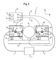
- Fig. 3 shows a front view of a device 1 according to the invention, in which each measuring nozzle 2, 3 is arranged with its associated pneumatic-electrical converter 6, 7 in a measuring head 9, 10.
- the compressed air supply channels 4, 5 are supplied by a compressor unit 11 with compressed air.
- Each pneumatic-electrical converter 6, 7 has a Messvordüse 34, a dynamic pressure sensor 35, a further pressure sensor 36 and a distance detection means 37.
- the compressed air supplied via the respective compressed air supply channel 4, 5 the respective converter 6, 7 compressed air is the Messvordüse 34 and then over the respective measuring nozzle 2, 3 passed to the workpiece 8.
- the air pressure p 1 which is referred to below as inlet pressure, in the respective compressed air supply channel 4, 5 with respect to the flow direction of the compressed air upstream of the measuring pre-34 measured.
- the dynamic pressure p 2 between the measuring pre-nozzle 34 and the respective measuring nozzle 2, 3 is measured by the respective transducer 6, 7.
- the ratio between dynamic pressure p 2 and inlet pressure p 1 is a measure of the distance between the respective measuring nozzle 2, 3 and the workpiece 8.
- the input pressure p 1 can be controlled with a control device to a predetermined pressure.
- the resulting back pressure p 2 can then be measured with the dynamic pressure sensor 35 and the dynamic pressure sensor 35 can this as electrical Feed the measured value to the distance determining device 37.
- the distance determination unit 37 comprises a memory and a processor.
- the memory is a characteristic which specifies the distance between the respective transducer 6, 7 and the workpiece 8 as a function of dynamic pressure for the given pressure deposited.
- the processor can thus determine the distance between the respective transducer 6, 7 and the workpiece 8 and output this as an electrical signal.
- both the input pressure p 1 and the dynamic pressure p 2 can be measured and then transmitted to the distance determining device 37 as electrical measured values.
- the processor of the distance determining device 37 determines from these measured values the ratio between the dynamic pressure p 2 and the inlet pressure p 1 . From a characteristic stored on the memory, which indicates the distance between the respective measuring nozzle 2, 3 and the workpiece 8 as a function of the ratio between dynamic pressure and inlet pressure, the processor can determine the respective distance. Alternatively, the processor may calculate the distance using a formula stored on the memory in which the calculated ratio is used as a function value. The respective determined distance can then be output by the converter 6, 7 as an electrical signal, for example as a digital electrical signal.
- the device 1 comprises an evaluation device 12 with a processor 13 and a display 14.
- the evaluation device 12 has the electrical inputs 15, 16 and 17.
- the pneumatic-electrical converter 6 is connected via an electrical line 31 to the electrical input 17, so that the electrical signal generated by the pneumatic-electrical converter 6, indicating the determined distance between the measuring nozzle 2 and the workpiece 8, for example in digitally coded form .
- the evaluation device 12, for example via a CAN bus connection, a Profibus connection or an Ethernet connection is supplied.
- the pneumatic-electrical converter 7 is connected via an electrical line 32 to the input 16, so that via the electrical signal generated by the pneumatic-electrical converter 7, the determined distance between the measuring nozzle 3 and the workpiece 8 also the evaluation unit 12 is supplied.
- the measuring head 9 is arranged on a cross slide 18 and the measuring head 10 on a cross slide 19.
- An electric brake 20 can be mounted on the cross slide 18 and an electric brake 21 can be arranged on the cross slide 19. With the electric brakes 20, 21, it is possible to lock the two cross slides 18, 19 each in a specific X and Y position, so that the measuring heads 9, 10 and thus the measuring nozzles 2, 3 are fixed in a desired position.
- a distance meter 22 can be arranged between the two cross slides 18, 19.
- the distance meter 22 may be an incremental encoder, which is also referred to as an encoder, which measures the adjustment path of the two cross slides 18, 19 relative to one another and is connected to the electrical input 15 of the evaluation device 12 via an electrical line 33 that an electrical signal, which is a measure of the distance between the cross slides 18 and 19 thus also for the distance between the measuring nozzles 2, 3, the evaluation device 12 is supplied.
- the two cross slides 18, 19 with the electric brakes 20, 21 and the distance meter 22 are arranged on a measuring table 23.
- the processor 13 is designed to form the sum of the two distances determined by the transducers 6, 7, which is then subtracted from the distance of the two measuring heads determined by the distance meter 22, from which the outer dimension of the workpiece results, which for example over the Display 14 can be displayed.
- the processor 13 is also designed to determine a specific external dimension, for example the maximum external dimension, from the measured external dimensions.
- the evaluation unit 12 controls the cross slides 18, 19 and the electric brakes 20, 21 and adjusts the cross slides 18, 19 so that the measuring nozzles 2.3 are positioned so that they with respect to the vertical Y-axis at the level of the specific external dimension , For example, the maximum outer dimension, are arranged.
- the evaluation unit 12 can also be provided to the course of the outer dimensions of the workpiece 8 along in Fig. 2 to store Z-axis shown when the workpiece 8 along the Z-axis between the measuring nozzles 2,3 moves through and is scanned.
- Fig. 4 illustrated conventional measuring device comprises a ring 24 with two measuring nozzles 25, 26 and a common compressed air supply channel 27, which branches into two sub-channels 28 and 29. Via a single pneumatic-electrical converter 30, the back pressure is measured, which results from the workpiece 8, over which the ring 24 was guided.
- the length of the compressed air supply channel 27 with the two sub-channels 28 and 29, respectively from the measuring nozzles 25, 26 to the pneumatic-electrical converter 30 in the conventional Device significantly longer than according to the device according to the invention.
- the measuring nozzles 25, 26 are difficult to access for cleaning.
- workpieces 8 with different diameters each have their own rings 24 are used.
Landscapes
- Physics & Mathematics (AREA)
- General Physics & Mathematics (AREA)
- Measuring Arrangements Characterized By The Use Of Fluids (AREA)
Applications Claiming Priority (1)
| Application Number | Priority Date | Filing Date | Title |
|---|---|---|---|
| DE102007050603A DE102007050603A1 (de) | 2007-10-23 | 2007-10-23 | Vorrichtung zur Messung des Aussendurchmessers von Werkstücken |
Publications (3)
| Publication Number | Publication Date |
|---|---|
| EP2053352A2 true EP2053352A2 (fr) | 2009-04-29 |
| EP2053352A3 EP2053352A3 (fr) | 2009-08-19 |
| EP2053352B1 EP2053352B1 (fr) | 2020-06-10 |
Family
ID=40291039
Family Applications (1)
| Application Number | Title | Priority Date | Filing Date |
|---|---|---|---|
| EP08018503.6A Active EP2053352B1 (fr) | 2007-10-23 | 2008-10-22 | Dispositif et procédé de mesure pneumatique d'une dimension extérieure de pièces usinées |
Country Status (2)
| Country | Link |
|---|---|
| EP (1) | EP2053352B1 (fr) |
| DE (1) | DE102007050603A1 (fr) |
Cited By (6)
| Publication number | Priority date | Publication date | Assignee | Title |
|---|---|---|---|---|
| EP3133370A1 (fr) | 2015-08-17 | 2017-02-22 | JENOPTIK Industrial Metrology Germany GmbH | Systeme de tuyere de mesure |
| CN107764214A (zh) * | 2017-11-17 | 2018-03-06 | 宁波慈兴轴承有限公司 | 一种柔性轴承外径测量夹具及其工作方法 |
| CN108827194A (zh) * | 2018-08-10 | 2018-11-16 | 昆明理工大学 | 一种电缆制品线径测量装置及方法 |
| CN114838678A (zh) * | 2022-07-04 | 2022-08-02 | 河北亿泰克轴承有限公司 | 一种薄壁轴承套圈外径气动测量装置 |
| US12194581B1 (en) * | 2023-04-04 | 2025-01-14 | Michael J. Stuck | Split bushing alignment assembly and method of use |
| EP4715326A1 (fr) * | 2024-09-23 | 2026-03-25 | JENOPTIK Industrial Metrology Germany GmbH | Dispositif de mesure pneumatique |
Citations (2)
| Publication number | Priority date | Publication date | Assignee | Title |
|---|---|---|---|---|
| JPS5855708A (ja) | 1981-09-29 | 1983-04-02 | Toyoda Mach Works Ltd | 温度補償機能を有する寸法測定装置 |
| EP0538771A1 (fr) | 1991-10-19 | 1993-04-28 | NEUMAN & ESSER MASCHINENFABRIK | Méthode pour détecter l'usure des pièces mécaniques mobiles |
Family Cites Families (2)
| Publication number | Priority date | Publication date | Assignee | Title |
|---|---|---|---|---|
| GB2020031B (en) * | 1978-04-27 | 1982-09-22 | Rolls Royce | Air gauges |
| US4550592A (en) * | 1984-05-07 | 1985-11-05 | Dechape Michel L | Pneumatic gauging circuit |
-
2007
- 2007-10-23 DE DE102007050603A patent/DE102007050603A1/de not_active Withdrawn
-
2008
- 2008-10-22 EP EP08018503.6A patent/EP2053352B1/fr active Active
Patent Citations (2)
| Publication number | Priority date | Publication date | Assignee | Title |
|---|---|---|---|---|
| JPS5855708A (ja) | 1981-09-29 | 1983-04-02 | Toyoda Mach Works Ltd | 温度補償機能を有する寸法測定装置 |
| EP0538771A1 (fr) | 1991-10-19 | 1993-04-28 | NEUMAN & ESSER MASCHINENFABRIK | Méthode pour détecter l'usure des pièces mécaniques mobiles |
Cited By (10)
| Publication number | Priority date | Publication date | Assignee | Title |
|---|---|---|---|---|
| EP3133370A1 (fr) | 2015-08-17 | 2017-02-22 | JENOPTIK Industrial Metrology Germany GmbH | Systeme de tuyere de mesure |
| DE102015113575A1 (de) | 2015-08-17 | 2017-02-23 | Jenoptik Industrial Metrology Germany Gmbh | Messdüsenanordnung |
| DE202015009644U1 (de) | 2015-08-17 | 2018-10-15 | Jenoptik Industrial Metrology Germany Gmbh | Messdüsenanordnung |
| DE102015113575B4 (de) * | 2015-08-17 | 2018-11-15 | Jenoptik Industrial Metrology Germany Gmbh | Messdüsenanordnung |
| CN107764214A (zh) * | 2017-11-17 | 2018-03-06 | 宁波慈兴轴承有限公司 | 一种柔性轴承外径测量夹具及其工作方法 |
| CN108827194A (zh) * | 2018-08-10 | 2018-11-16 | 昆明理工大学 | 一种电缆制品线径测量装置及方法 |
| CN114838678A (zh) * | 2022-07-04 | 2022-08-02 | 河北亿泰克轴承有限公司 | 一种薄壁轴承套圈外径气动测量装置 |
| CN114838678B (zh) * | 2022-07-04 | 2022-09-02 | 河北亿泰克轴承有限公司 | 一种薄壁轴承套圈外径气动测量装置 |
| US12194581B1 (en) * | 2023-04-04 | 2025-01-14 | Michael J. Stuck | Split bushing alignment assembly and method of use |
| EP4715326A1 (fr) * | 2024-09-23 | 2026-03-25 | JENOPTIK Industrial Metrology Germany GmbH | Dispositif de mesure pneumatique |
Also Published As
| Publication number | Publication date |
|---|---|
| DE102007050603A1 (de) | 2009-04-30 |
| EP2053352B1 (fr) | 2020-06-10 |
| EP2053352A3 (fr) | 2009-08-19 |
Similar Documents
| Publication | Publication Date | Title |
|---|---|---|
| EP2053352B1 (fr) | Dispositif et procédé de mesure pneumatique d'une dimension extérieure de pièces usinées | |
| EP3163586B1 (fr) | Dispositif de câblage de lignes électriques | |
| EP2794136B1 (fr) | Procédé et dispositif de refroidissement de cylindres | |
| WO1991017004A1 (fr) | Procede de commande des mouvements de revolution du cylindre d'impression d'une machine a imprimer et machine a imprimer pour mettre en ×uvre ce procede | |
| EP4491367A1 (fr) | Dispositif d'extrusion, extrudeuse et procédé pour enrober des fils, des produits semi-finis de câbles ou des torons | |
| DE3224980C2 (de) | Selbsttätig arbeitendes Zahnradprüfgerät | |
| EP2233249A1 (fr) | Système pour serrer simultanément plusieurs boulonnages en une étape | |
| DE2931273C2 (de) | Vorrichtung zur Prüfung eines Gewindes | |
| DE4308283C2 (de) | Meßvorrichtung zum Messen von Längen oder anderen Maßkriterien an Werkstücken | |
| AT410195B (de) | Verfahren und einrichtung zur anpassung eines extrusionswerkzeuges an einen extruder | |
| DE2711862A1 (de) | Honmaschine | |
| EP0671599B1 (fr) | Procédé et appareil de mesure pneumatique pour contrôler des dimensions d'un objet | |
| EP0483402A1 (fr) | Procédé et dispositif pour mesurer la géométrie d'alésages | |
| DE102007020172A1 (de) | Vorrichtung und Verfahren zum räumlichen Vermessen von Werkstücken an einer Werkzeugmaschine | |
| DE2164332C3 (de) | Regelvorrichtung zur Längung eines Strangabschnittes | |
| EP0594018A1 (fr) | Appareil d'extrusion de profilés plastiques | |
| EP0595198A1 (fr) | Appareil et méthode pour la fabrication de profilés allongés en matières plastiques | |
| DE102021109812A1 (de) | Verfahren und Bearbeitungsmaschine zur Ermittlung des Zustandes eines Ritzel-Zahnstangenantriebs für eine verfahrbare Achse | |
| EP2053351A2 (fr) | Système de mesure, notamment pour la mesure de rainures | |
| DE1183700B (de) | Selbsttaetig arbeitendes Zahnradpruefgeraet | |
| DE1448966B2 (de) | Pneumatische Längenmeßeinrichtung | |
| DE10145740B4 (de) | Verfahren zum Aufbringen des Schließdruckes auf die geschlossene Form einer Spritzgießmaschine | |
| DE102009021122A1 (de) | Verfahren zur Bearbeitung eines Werkstücks durch ein Werkzeug sowie Vorrichtung zur Durchführung des Verfahrens | |
| AT509764A1 (de) | Messvorrichtung einer druckmaschine | |
| DE1448966C (de) | Pneumatische Langenmeßeinnchtung |
Legal Events
| Date | Code | Title | Description |
|---|---|---|---|
| PUAI | Public reference made under article 153(3) epc to a published international application that has entered the european phase |
Free format text: ORIGINAL CODE: 0009012 |
|
| AK | Designated contracting states |
Kind code of ref document: A2 Designated state(s): AT BE BG CH CY CZ DE DK EE ES FI FR GB GR HR HU IE IS IT LI LT LU LV MC MT NL NO PL PT RO SE SI SK TR |
|
| AX | Request for extension of the european patent |
Extension state: AL BA MK RS |
|
| PUAL | Search report despatched |
Free format text: ORIGINAL CODE: 0009013 |
|
| AK | Designated contracting states |
Kind code of ref document: A3 Designated state(s): AT BE BG CH CY CZ DE DK EE ES FI FR GB GR HR HU IE IS IT LI LT LU LV MC MT NL NO PL PT RO SE SI SK TR |
|
| AX | Request for extension of the european patent |
Extension state: AL BA MK RS |
|
| 17P | Request for examination filed |
Effective date: 20100215 |
|
| 17Q | First examination report despatched |
Effective date: 20100312 |
|
| AKX | Designation fees paid |
Designated state(s): AT BE BG CH CY CZ DE DK EE ES FI FR GB GR HR HU IE IS IT LI LT LU LV MC MT NL NO PL PT RO SE SI SK TR |
|
| STAA | Information on the status of an ep patent application or granted ep patent |
Free format text: STATUS: EXAMINATION IS IN PROGRESS |
|
| GRAP | Despatch of communication of intention to grant a patent |
Free format text: ORIGINAL CODE: EPIDOSNIGR1 |
|
| STAA | Information on the status of an ep patent application or granted ep patent |
Free format text: STATUS: GRANT OF PATENT IS INTENDED |
|
| INTG | Intention to grant announced |
Effective date: 20200220 |
|
| GRAS | Grant fee paid |
Free format text: ORIGINAL CODE: EPIDOSNIGR3 |
|
| GRAA | (expected) grant |
Free format text: ORIGINAL CODE: 0009210 |
|
| STAA | Information on the status of an ep patent application or granted ep patent |
Free format text: STATUS: THE PATENT HAS BEEN GRANTED |
|
| AK | Designated contracting states |
Kind code of ref document: B1 Designated state(s): AT BE BG CH CY CZ DE DK EE ES FI FR GB GR HR HU IE IS IT LI LT LU LV MC MT NL NO PL PT RO SE SI SK TR |
|
| REG | Reference to a national code |
Ref country code: GB Ref legal event code: FG4D Free format text: NOT ENGLISH |
|
| REG | Reference to a national code |
Ref country code: AT Ref legal event code: REF Ref document number: 1279540 Country of ref document: AT Kind code of ref document: T Effective date: 20200615 Ref country code: CH Ref legal event code: EP |
|
| REG | Reference to a national code |
Ref country code: DE Ref legal event code: R096 Ref document number: 502008017093 Country of ref document: DE |
|
| REG | Reference to a national code |
Ref country code: CH Ref legal event code: NV Representative=s name: DR. GRAF AND PARTNER AG INTELLECTUAL PROPERTY, CH |
|
| REG | Reference to a national code |
Ref country code: IE Ref legal event code: FG4D Free format text: LANGUAGE OF EP DOCUMENT: GERMAN |
|
| REG | Reference to a national code |
Ref country code: LT Ref legal event code: MG4D |
|
| PG25 | Lapsed in a contracting state [announced via postgrant information from national office to epo] |
Ref country code: NO Free format text: LAPSE BECAUSE OF FAILURE TO SUBMIT A TRANSLATION OF THE DESCRIPTION OR TO PAY THE FEE WITHIN THE PRESCRIBED TIME-LIMIT Effective date: 20200910 Ref country code: GR Free format text: LAPSE BECAUSE OF FAILURE TO SUBMIT A TRANSLATION OF THE DESCRIPTION OR TO PAY THE FEE WITHIN THE PRESCRIBED TIME-LIMIT Effective date: 20200911 Ref country code: FI Free format text: LAPSE BECAUSE OF FAILURE TO SUBMIT A TRANSLATION OF THE DESCRIPTION OR TO PAY THE FEE WITHIN THE PRESCRIBED TIME-LIMIT Effective date: 20200610 Ref country code: LT Free format text: LAPSE BECAUSE OF FAILURE TO SUBMIT A TRANSLATION OF THE DESCRIPTION OR TO PAY THE FEE WITHIN THE PRESCRIBED TIME-LIMIT Effective date: 20200610 Ref country code: SE Free format text: LAPSE BECAUSE OF FAILURE TO SUBMIT A TRANSLATION OF THE DESCRIPTION OR TO PAY THE FEE WITHIN THE PRESCRIBED TIME-LIMIT Effective date: 20200610 |
|
| REG | Reference to a national code |
Ref country code: NL Ref legal event code: MP Effective date: 20200610 |
|
| PG25 | Lapsed in a contracting state [announced via postgrant information from national office to epo] |
Ref country code: BG Free format text: LAPSE BECAUSE OF FAILURE TO SUBMIT A TRANSLATION OF THE DESCRIPTION OR TO PAY THE FEE WITHIN THE PRESCRIBED TIME-LIMIT Effective date: 20200910 Ref country code: HR Free format text: LAPSE BECAUSE OF FAILURE TO SUBMIT A TRANSLATION OF THE DESCRIPTION OR TO PAY THE FEE WITHIN THE PRESCRIBED TIME-LIMIT Effective date: 20200610 Ref country code: LV Free format text: LAPSE BECAUSE OF FAILURE TO SUBMIT A TRANSLATION OF THE DESCRIPTION OR TO PAY THE FEE WITHIN THE PRESCRIBED TIME-LIMIT Effective date: 20200610 |
|
| PG25 | Lapsed in a contracting state [announced via postgrant information from national office to epo] |
Ref country code: NL Free format text: LAPSE BECAUSE OF FAILURE TO SUBMIT A TRANSLATION OF THE DESCRIPTION OR TO PAY THE FEE WITHIN THE PRESCRIBED TIME-LIMIT Effective date: 20200610 |
|
| PG25 | Lapsed in a contracting state [announced via postgrant information from national office to epo] |
Ref country code: EE Free format text: LAPSE BECAUSE OF FAILURE TO SUBMIT A TRANSLATION OF THE DESCRIPTION OR TO PAY THE FEE WITHIN THE PRESCRIBED TIME-LIMIT Effective date: 20200610 Ref country code: ES Free format text: LAPSE BECAUSE OF FAILURE TO SUBMIT A TRANSLATION OF THE DESCRIPTION OR TO PAY THE FEE WITHIN THE PRESCRIBED TIME-LIMIT Effective date: 20200610 Ref country code: PT Free format text: LAPSE BECAUSE OF FAILURE TO SUBMIT A TRANSLATION OF THE DESCRIPTION OR TO PAY THE FEE WITHIN THE PRESCRIBED TIME-LIMIT Effective date: 20201012 Ref country code: RO Free format text: LAPSE BECAUSE OF FAILURE TO SUBMIT A TRANSLATION OF THE DESCRIPTION OR TO PAY THE FEE WITHIN THE PRESCRIBED TIME-LIMIT Effective date: 20200610 Ref country code: IT Free format text: LAPSE BECAUSE OF FAILURE TO SUBMIT A TRANSLATION OF THE DESCRIPTION OR TO PAY THE FEE WITHIN THE PRESCRIBED TIME-LIMIT Effective date: 20200610 Ref country code: CZ Free format text: LAPSE BECAUSE OF FAILURE TO SUBMIT A TRANSLATION OF THE DESCRIPTION OR TO PAY THE FEE WITHIN THE PRESCRIBED TIME-LIMIT Effective date: 20200610 |
|
| PG25 | Lapsed in a contracting state [announced via postgrant information from national office to epo] |
Ref country code: IS Free format text: LAPSE BECAUSE OF FAILURE TO SUBMIT A TRANSLATION OF THE DESCRIPTION OR TO PAY THE FEE WITHIN THE PRESCRIBED TIME-LIMIT Effective date: 20201010 Ref country code: PL Free format text: LAPSE BECAUSE OF FAILURE TO SUBMIT A TRANSLATION OF THE DESCRIPTION OR TO PAY THE FEE WITHIN THE PRESCRIBED TIME-LIMIT Effective date: 20200610 Ref country code: SK Free format text: LAPSE BECAUSE OF FAILURE TO SUBMIT A TRANSLATION OF THE DESCRIPTION OR TO PAY THE FEE WITHIN THE PRESCRIBED TIME-LIMIT Effective date: 20200610 |
|
| REG | Reference to a national code |
Ref country code: DE Ref legal event code: R097 Ref document number: 502008017093 Country of ref document: DE |
|
| PLBE | No opposition filed within time limit |
Free format text: ORIGINAL CODE: 0009261 |
|
| STAA | Information on the status of an ep patent application or granted ep patent |
Free format text: STATUS: NO OPPOSITION FILED WITHIN TIME LIMIT |
|
| PG25 | Lapsed in a contracting state [announced via postgrant information from national office to epo] |
Ref country code: DK Free format text: LAPSE BECAUSE OF FAILURE TO SUBMIT A TRANSLATION OF THE DESCRIPTION OR TO PAY THE FEE WITHIN THE PRESCRIBED TIME-LIMIT Effective date: 20200610 |
|
| 26N | No opposition filed |
Effective date: 20210311 |
|
| PG25 | Lapsed in a contracting state [announced via postgrant information from national office to epo] |
Ref country code: SI Free format text: LAPSE BECAUSE OF FAILURE TO SUBMIT A TRANSLATION OF THE DESCRIPTION OR TO PAY THE FEE WITHIN THE PRESCRIBED TIME-LIMIT Effective date: 20200610 |
|
| REG | Reference to a national code |
Ref country code: CH Ref legal event code: PL |
|
| GBPC | Gb: european patent ceased through non-payment of renewal fee |
Effective date: 20201022 |
|
| PG25 | Lapsed in a contracting state [announced via postgrant information from national office to epo] |
Ref country code: MC Free format text: LAPSE BECAUSE OF FAILURE TO SUBMIT A TRANSLATION OF THE DESCRIPTION OR TO PAY THE FEE WITHIN THE PRESCRIBED TIME-LIMIT Effective date: 20200610 Ref country code: LU Free format text: LAPSE BECAUSE OF NON-PAYMENT OF DUE FEES Effective date: 20201022 |
|
| REG | Reference to a national code |
Ref country code: BE Ref legal event code: MM Effective date: 20201031 |
|
| PG25 | Lapsed in a contracting state [announced via postgrant information from national office to epo] |
Ref country code: FR Free format text: LAPSE BECAUSE OF NON-PAYMENT OF DUE FEES Effective date: 20201031 |
|
| PG25 | Lapsed in a contracting state [announced via postgrant information from national office to epo] |
Ref country code: LI Free format text: LAPSE BECAUSE OF NON-PAYMENT OF DUE FEES Effective date: 20201031 Ref country code: GB Free format text: LAPSE BECAUSE OF NON-PAYMENT OF DUE FEES Effective date: 20201022 Ref country code: BE Free format text: LAPSE BECAUSE OF NON-PAYMENT OF DUE FEES Effective date: 20201031 Ref country code: CH Free format text: LAPSE BECAUSE OF NON-PAYMENT OF DUE FEES Effective date: 20201031 |
|
| PG25 | Lapsed in a contracting state [announced via postgrant information from national office to epo] |
Ref country code: IE Free format text: LAPSE BECAUSE OF NON-PAYMENT OF DUE FEES Effective date: 20201022 |
|
| REG | Reference to a national code |
Ref country code: AT Ref legal event code: MM01 Ref document number: 1279540 Country of ref document: AT Kind code of ref document: T Effective date: 20201022 |
|
| PG25 | Lapsed in a contracting state [announced via postgrant information from national office to epo] |
Ref country code: AT Free format text: LAPSE BECAUSE OF NON-PAYMENT OF DUE FEES Effective date: 20201022 |
|
| PG25 | Lapsed in a contracting state [announced via postgrant information from national office to epo] |
Ref country code: TR Free format text: LAPSE BECAUSE OF FAILURE TO SUBMIT A TRANSLATION OF THE DESCRIPTION OR TO PAY THE FEE WITHIN THE PRESCRIBED TIME-LIMIT Effective date: 20200610 Ref country code: MT Free format text: LAPSE BECAUSE OF FAILURE TO SUBMIT A TRANSLATION OF THE DESCRIPTION OR TO PAY THE FEE WITHIN THE PRESCRIBED TIME-LIMIT Effective date: 20200610 Ref country code: CY Free format text: LAPSE BECAUSE OF FAILURE TO SUBMIT A TRANSLATION OF THE DESCRIPTION OR TO PAY THE FEE WITHIN THE PRESCRIBED TIME-LIMIT Effective date: 20200610 |
|
| PGFP | Annual fee paid to national office [announced via postgrant information from national office to epo] |
Ref country code: DE Payment date: 20251229 Year of fee payment: 18 |