EP2053377A1 - Procédé et dispositif destinés à la microdissection tridimensionnelle - Google Patents
Procédé et dispositif destinés à la microdissection tridimensionnelle Download PDFInfo
- Publication number
- EP2053377A1 EP2053377A1 EP07020582A EP07020582A EP2053377A1 EP 2053377 A1 EP2053377 A1 EP 2053377A1 EP 07020582 A EP07020582 A EP 07020582A EP 07020582 A EP07020582 A EP 07020582A EP 2053377 A1 EP2053377 A1 EP 2053377A1
- Authority
- EP
- European Patent Office
- Prior art keywords
- sample
- laser
- structures
- control unit
- axis
- Prior art date
- Legal status (The legal status is an assumption and is not a legal conclusion. Google has not performed a legal analysis and makes no representation as to the accuracy of the status listed.)
- Withdrawn
Links
Images
Classifications
-
- G—PHYSICS
- G01—MEASURING; TESTING
- G01N—INVESTIGATING OR ANALYSING MATERIALS BY DETERMINING THEIR CHEMICAL OR PHYSICAL PROPERTIES
- G01N1/00—Sampling; Preparing specimens for investigation
- G01N1/28—Preparing specimens for investigation including physical details of (bio-)chemical methods covered elsewhere, e.g. G01N33/50, C12Q
- G01N1/2813—Producing thin layers of samples on a substrate, e.g. smearing, spinning-on
-
- G—PHYSICS
- G01—MEASURING; TESTING
- G01N—INVESTIGATING OR ANALYSING MATERIALS BY DETERMINING THEIR CHEMICAL OR PHYSICAL PROPERTIES
- G01N1/00—Sampling; Preparing specimens for investigation
- G01N1/02—Devices for withdrawing samples
- G01N1/04—Devices for withdrawing samples in the solid state, e.g. by cutting
- G01N1/06—Devices for withdrawing samples in the solid state, e.g. by cutting providing a thin slice, e.g. microtome
-
- G—PHYSICS
- G01—MEASURING; TESTING
- G01N—INVESTIGATING OR ANALYSING MATERIALS BY DETERMINING THEIR CHEMICAL OR PHYSICAL PROPERTIES
- G01N1/00—Sampling; Preparing specimens for investigation
- G01N1/28—Preparing specimens for investigation including physical details of (bio-)chemical methods covered elsewhere, e.g. G01N33/50, C12Q
- G01N1/42—Low-temperature sample treatment, e.g. cryofixation
-
- G—PHYSICS
- G01—MEASURING; TESTING
- G01N—INVESTIGATING OR ANALYSING MATERIALS BY DETERMINING THEIR CHEMICAL OR PHYSICAL PROPERTIES
- G01N1/00—Sampling; Preparing specimens for investigation
- G01N1/28—Preparing specimens for investigation including physical details of (bio-)chemical methods covered elsewhere, e.g. G01N33/50, C12Q
- G01N1/286—Preparing specimens for investigation including physical details of (bio-)chemical methods covered elsewhere, e.g. G01N33/50, C12Q involving mechanical work, e.g. chopping, disintegrating, compacting, homogenising
- G01N2001/2873—Cutting or cleaving
- G01N2001/2886—Laser cutting, e.g. tissue catapult
Definitions
- the present invention relates to a method for the separation of defined three-dimensional structures, in particular from biological objects, and to an apparatus for carrying out this method.
- microdissection allows the targeted isolation of mostly biological material from a sample.
- mechanical or two-dimensional laser-based microdissection methods and devices are usually used, by means of which cut out of the most biological samples defined structures and can catch.
- a two-dimensional laser-based microdissection method is for example in DE 10 2006 000 934 A1 described.
- a biological preparation for example a histological tissue section
- a carrier is applied to a carrier.
- a selection of the preparation by laser irradiation takes place, wherein a computer controls a motor-driven microscope stage on which the carrier is located. After cutting out an object, it is accelerated by a laser shot and caught by a catcher.
- the release of the structures to be separated takes place here by means of direction information in two spatial directions.
- the maximum cuttable layer thickness is usually about 100 microns. Larger volumes with correspondingly greater layer thicknesses can not be separated with known laser microdissection methods.
- the classical laser microdissection methods are all based on microscopic constructions in which the degrees of freedom of movement are limited to the axes perpendicular to the optical axis.
- the classical processing method also requires a complex sample preparation, since the sample layers to be processed must first be prepared in advance. Usually already the sample preparation leads to changes and degeneration of the material to be examined in the last process step. Furthermore, a freezing of the sample during the entire processing in the known laser-based microdissection method is not possible.
- the microscopic structure of classical systems forces the use of a common optical component, the objective, to focus the laser as well as the imaging.
- a common optical component the objective
- Such a combination imposes compromises between the imaging character of the objective in the visible light wavelength range as well as the transmission of the laser and the quality of the laser focusing.
- the submillimeter range here comprises characteristic lengths of the structures to be separated up to to a millimeter or a volume of the structures to be separated to about 1 mm 3 .
- Cold laser ablation is understood to mean the removal of material by irradiation with short-wave laser light, so that the sample is not heated by photon absorption. The laser light does not excite the molecular rotation or. Vibration bands on.
- material processing can be based on multiphoton absorption processes.
- Multiphoton absorption processes produce a very high photon density.
- the simultaneous absorption of several photons by the material is probable and the sum of the energies of the single photons is introduced into the material.
- highly focused lasers with extremely short laser pulses in the picosecond or femtosecond range are used to generate the high photon densities.
- the sample is a biological material.
- the laser emits pulses having pulse times less than 5 ns.
- a three-dimensional volume model according to step a) takes place by means of an imaging method that can detect at least the structures to be separated in their three-dimensional structures.
- Imaging techniques have undergone considerable development for three-dimensional structures in recent years. There are standardized methods and systems are available and can therefore be effectively and inexpensively integrated into the present method.
- the imaging method includes one of the following methods: magnetic resonance imaging, computed tomography, ultrasound, 3D modeling by light microscopy visualization techniques; the above-mentioned methods are particularly widespread and mature and are therefore particularly suitable for use in the present invention.
- the imaging involves a resolution in the 10 micron range. Imaging methods of today's generation can achieve resolution in this area and therefore contribute to meeting the demand for a particularly high separation precision in the present method. Alternatively, volume models can also be created or drawn directly by the user due to parameterization.
- optical parameters for calibration and / or referencing are used to bring the position and orientation of the three-dimensional volume model into agreement with those introduced into the 3D microdissection system.
- Optical parameters may be structural features already present in the sample or may be artificially applied or incorporated. In order to be able to carry out a fully automatic separation process, it is helpful to orient the sample as precisely as possible in relation to the volume model. Aligning over optical parameters is preferable because alignment with software can be accomplished using optical devices that may be at least partially present. Thus, a particularly high alignment precision can be achieved, which contributes to the To meet the demand for a particularly high separation precision in the present invention.
- the method of the present invention further comprises step a1) to be performed prior to step b), namely, preparing the sample to allow the volume to be separated therefrom to be removed, wherein the preparation of the sample includes one of the following methods: embedding the sample in plastic materials, embedding the sample in long-chain organic substances such as wax or paraffin, soaking the samples with plasticizing liquids, deep-freezing the sample; Such preparation of the sample contributes to the avoidance of microstructural transformations in the three-dimensional cold laser ablation process, so that non-or at least less degraded structures can be separated.
- the sample preparation involves freezing the sample to temperatures below 4 ° C. Cooling the sample provides a particularly simple, quick and inexpensive way to reduce microstructural changes during the manufacturing process.
- the relative movement between laser focus and sample can also be realized by an arrangement in which the laser assembly is mounted on a robotic system and thus can be moved with sufficient degrees of freedom and the sample is fixedly mounted.
- the necessary degrees of freedom may be distributed between movement of the laser assembly and movement of the sample.
- the release of the structures to be separated by means of a laser device which is at least partially in an ablation, in which the cropping of the structures to be separated takes place, is carried out.
- Lasers have recently gained importance as cutting tools because they allow a particularly high accuracy of the cuts. Cuts can be precisely performed in a way that does not or only slightly affect surrounding structures. Thus, no or at least little degraded structures can be separated with high precision.
- step b) is performed on an at least partially frozen sample.
- the present method allows separation on a frozen sample, which significantly helps to avoid microstructural changes.
- the method may be characterized in that a spatial dimension of the sample is at least an order of magnitude smaller than the other two.
- the method according to the present invention comprises the step of monitoring the ablation procedure using a camera arrangement.
- monitoring by a camera system is an option that is easy to install and inexpensive.
- the camera assembly is connected to the control unit, which is used by image processing techniques and the characteristic optical parameters to calibrate and / or reference the absolute orientation of the sample, the method calibrating the additional step to be performed between steps b1) and b3) the sample comprising the three-dimensional volume model.
- the camera arrangement can be suitably used in addition to the monitoring of the method for the orientation of the sample. Thus, due to the dual function costs and space requirements can be saved.
- the imaging system can be based on commercially available microscopes to which a camera can be connected.
- the method of the present invention comprises step c) to be performed during and / or after step b), separating and removing the separated structures, the step including at least one of the following methods: collecting the falling separated structures in collection vessels, firing partially separated structures by means of a laser shot, Removal by adhesion, removal by suction, removal by rinsing, removal by ultrasound, removal by electrostatics; the above methods are particularly suitable for the removal and possibly final separation of the VOI, since they are simple and inexpensive to carry out.
- the sample holder can also be moved by means of an adjusting device along a third axis H, wherein the control unit is connected to this adjusting device and can cause the adjusting device to move the sample holder along the axis H.
- the control unit is connected to this adjusting device and can cause the adjusting device to move the sample holder along the axis H.
- the laser device preferably has a laser actuator connected to the control unit, wherein the tilt angle of the laser beam can be adjusted by the control unit.
- the sample holder is a mechanical holder or a holder to which the sample is fixed by means of embedding in a gel or the like.
- the ablation chamber has a cooling device that can cool the chamber so that the sample is cooled, preferably frozen, or can be maintained in a cooled state, preferably a frozen state. Cooling the sample provides a particularly simple, quick and inexpensive way to reduce microstructural changes during the manufacturing process.
- the temperature in the ablation chamber is preferably less than 4 ° C, typically about -18 ° C, since at these temperatures microstructural transformations are significantly reduced over time.
- the optical axis of the laser is perpendicular to the axis of rotation R, wherein the axes of rotation R and V coincide and are perpendicular to the axis H.
- the vertical or parallel arrangement of the axes can be carried out with high accuracy. Furthermore, such an arrangement can simplify the calculation of the sequence of movements.
- two collecting vessels A1 and A2 are provided below the sample in the ablation chamber.
- the removal and separation of the VOI by means of collecting container is simple and inexpensive to carry out.
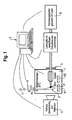
- FIG. 1 schematically shows an apparatus for separating defined three-dimensional structures from a sample according to an embodiment of the present invention.
- FIG. 1 schematically shows an apparatus for separating defined three-dimensional structures from a sample according to an embodiment of the invention.
- the researcherSlende volume is also referred to below as VOI (volume of interest).
- a sample head is located in an ablation chamber 1 with a sample 2.
- the ablation chamber 1 comprises a housing in which the peeling of defined three-dimensional structures from the sample is carried out.
- the probe head is displaceable along a vertical axis V and a horizontal axis H and arranged rotatable about a rotation axis R.
- the axes V and R may be identical as in the present embodiment.
- the movements of the probe head along the axis V and H and about the axis R is motorized by means of corresponding adjusting devices, which in the FIG. 1 not shown.
- the probe head and the sample are movable according to this embodiment by three degrees of freedom.
- the sample holder may be, for example, a mechanical holder or may be designed such that the sample is fixed by embedding in a gel or the like.
- the ablation chamber 1 contains a cooling device, which is not shown in the figure, so that the sample in the chamber can be frozen or maintained in a frozen state.
- the cooling device may comprise conventional refrigerating machines and sensors in order to be able to set and maintain the temperature inside the ablation chamber 1 at a desired value.
- the sample is prepared by means of a laser device 6 which, in addition to a high-energy, pulsed UV laser, comprises an adjustable laser optic with objective and is introduced at least partially into the ablation chamber 1 through a laser window 3.
- an objective of the laser device 6 is located within the ablation chamber 1.
- the laser device 6 or a part of the laser device can also be arranged rotatably and / or displaceably can be.
- a tilting function of the laser beam relative to the optical axis of the laser may be provided to shift the focal point P of the laser.
- control unit 5 which in the present embodiment comprises a PC. This is connected to the laser device 6 and the adjusting devices. Further, the PC may be connected to the cooling device to monitor the temperature inside the ablation chamber 1.
- the preparation process is monitored by means of a camera assembly 4, which is also connected to the PC.
- a camera assembly 4 which is also connected to the PC.
- the camera assembly 4 in the figure is indicated outside the ablation chamber 1, it may also be provided within the ablation chamber 1.
- the camera assembly 4 is not only for monitoring and quality assurance but is also used to calibrate and reference characteristic optical parameters to match the sample to a solid model, as described below.
- a three-dimensional volume model of the sample or at least the areas to be separated is created or procured.
- models for example also theoretical models, of the sample can be used.
- an imaging method such as magnetic resonance tomography, computed tomography, ultrasound or light microscopic methods, is used.
- the volumes to be extracted are determined by a three-dimensional data field, this data field being determined by the user by selecting the volume to be selected.
- the determination of the VOI can be done on the basis of prefabricated created volume models as well as direct 3D visualizations of the object to be processed. Alternatively, the VOI can also be calculated and created from parameterizations or freehand drawings entered directly by the user.
- a sample is introduced into a preferably cooled to -18 ° C ablation 1 and fixed with the sample holder.
- reference methods such as calibration points or referencing via characteristic optical parameters must be introduced.
- the referencing can be done either via artificially applied reference points or via characteristic structures of the object to be processed.
- One possible realization of the optical visualization consists of observing the sample with a macro objective and a digital camera, which are contained in the camera arrangement 4. The lens and the camera may be provided directly in the ablation chamber 1.
- the referencing and calibration can be done by means of the camera arrangement 4 and known image processing methods. Aligning the sample with the solid model means determining a coordinate system of the data field relative to the clamped sample via a reference method.
- the calculation of a sequence of movements can be carried out, after which the control unit 5 controls the adjusting devices and the laser so that it separates the areas to be separated. From the VOI, a motion algorithm is calculated, which makes it possible to fully outshoot the VOI in its entirety or in the form of fragments.
- a laser is introduced through the laser window 3 and focused on the sample by means of a lens.
- the optical axis of the laser is substantially perpendicular to the axis of rotation R.
- Laser parameters such as laser power and focus position are adjustable and can be suitably adjusted by the control unit 5.
- the ablation process preferably starts at the lowest point of the sample and carries material along the axes V and H during the rotation of the sample about the axis of rotation R and moving the sample according to the calculated sequence of movements.
- the abraded material falls into a collecting vessel A1, which is provided below the sample in the ablation chamber 1. If a target volume has been scanned, it is cut off from the rest of the sample by a laser beam and falls into a collecting vessel A2, which is likewise provided below the sample in the ablation chamber 1.
- the collecting container A1 and A2 can be exchanged or moved, or the probe head can be arranged by means of the adjusting devices directly above the respective collecting container.
- An additional image processing module can determine the separated volumes and thus assume an automatic quality control.
Landscapes
- Physics & Mathematics (AREA)
- Health & Medical Sciences (AREA)
- Life Sciences & Earth Sciences (AREA)
- Chemical & Material Sciences (AREA)
- Analytical Chemistry (AREA)
- Biochemistry (AREA)
- General Health & Medical Sciences (AREA)
- General Physics & Mathematics (AREA)
- Immunology (AREA)
- Pathology (AREA)
- Sampling And Sample Adjustment (AREA)
- Microscoopes, Condenser (AREA)
Priority Applications (4)
| Application Number | Priority Date | Filing Date | Title |
|---|---|---|---|
| EP07020582A EP2053377A1 (fr) | 2007-10-22 | 2007-10-22 | Procédé et dispositif destinés à la microdissection tridimensionnelle |
| CN200810170055.1A CN101419223B (zh) | 2007-10-22 | 2008-10-22 | 用于三维显微解剖的方法和装置 |
| US12/256,341 US9200989B2 (en) | 2007-10-22 | 2008-10-22 | Method and device for three dimensional microdissection |
| JP2008271802A JP2009103701A (ja) | 2007-10-22 | 2008-10-22 | 三次元マイクロダイセクションのための方法および装置 |
Applications Claiming Priority (1)
| Application Number | Priority Date | Filing Date | Title |
|---|---|---|---|
| EP07020582A EP2053377A1 (fr) | 2007-10-22 | 2007-10-22 | Procédé et dispositif destinés à la microdissection tridimensionnelle |
Publications (1)
| Publication Number | Publication Date |
|---|---|
| EP2053377A1 true EP2053377A1 (fr) | 2009-04-29 |
Family
ID=39327227
Family Applications (1)
| Application Number | Title | Priority Date | Filing Date |
|---|---|---|---|
| EP07020582A Withdrawn EP2053377A1 (fr) | 2007-10-22 | 2007-10-22 | Procédé et dispositif destinés à la microdissection tridimensionnelle |
Country Status (4)
| Country | Link |
|---|---|
| US (1) | US9200989B2 (fr) |
| EP (1) | EP2053377A1 (fr) |
| JP (1) | JP2009103701A (fr) |
| CN (1) | CN101419223B (fr) |
Families Citing this family (18)
| Publication number | Priority date | Publication date | Assignee | Title |
|---|---|---|---|---|
| US10156501B2 (en) | 2001-11-05 | 2018-12-18 | Life Technologies Corporation | Automated microdissection instrument for determining a location of a laser beam projection on a worksurface area |
| US8722357B2 (en) * | 2001-11-05 | 2014-05-13 | Life Technologies Corporation | Automated microdissection instrument |
| EP2406679B1 (fr) | 2009-03-11 | 2017-01-25 | Sakura Finetek U.S.A., Inc. | Procédé d'autofocus et système d'autofocus |
| US10139613B2 (en) | 2010-08-20 | 2018-11-27 | Sakura Finetek U.S.A., Inc. | Digital microscope and method of sensing an image of a tissue sample |
| WO2012102779A2 (fr) | 2011-01-24 | 2012-08-02 | Adey Nils B | Dispositifs, systèmes et méthodes d'extraction d'un matériau d'un échantillon de matériau |
| JP5975462B2 (ja) * | 2012-03-21 | 2016-08-23 | 国立大学法人九州大学 | アブレーション装置及び3次元電子顕微鏡 |
| US8371182B1 (en) * | 2012-06-11 | 2013-02-12 | Jacob Israelachvili | Mounting systems for a surface forces apparatus |
| DE102013103971A1 (de) | 2013-04-19 | 2014-11-06 | Sensovation Ag | Verfahren zum Erzeugen eines aus mehreren Teilbildern zusammengesetzten Gesamtbilds eines Objekts |
| DE102013109481A1 (de) * | 2013-08-30 | 2015-03-05 | Firma Leica Microsystems CMS GmbH | Lasermikrodissektionssystem und Lasermikrodissektionsverfahren |
| US10007102B2 (en) | 2013-12-23 | 2018-06-26 | Sakura Finetek U.S.A., Inc. | Microscope with slide clamping assembly |
| EP3250900B1 (fr) | 2015-01-31 | 2021-08-18 | Roche Diagnostics GmbH | Systèmes et procédés destinés à une méso-dissection |
| WO2016120433A1 (fr) | 2015-01-31 | 2016-08-04 | Roche Diagnostics Gmbh | Systèmes et procédés pour méso-dissection |
| EP3273285A4 (fr) * | 2015-03-18 | 2018-11-21 | National Tsing Hua University | Système optique pour imagerie en trois dimensions à grande vitesse |
| JP6796379B2 (ja) * | 2016-01-20 | 2020-12-09 | 地方独立行政法人東京都立産業技術研究センター | レーザーマイクロダイセクター及びレーザーマイクロダイセクション方法 |
| JP6765192B2 (ja) * | 2016-01-20 | 2020-10-07 | 地方独立行政法人東京都立産業技術研究センター | レーザーマイクロダイセクター及びレーザーマイクロダイセクション方法 |
| CN110140040A (zh) | 2016-11-09 | 2019-08-16 | 豪夫迈·罗氏有限公司 | 自动化的组织切割仪器及其使用方法 |
| US11280803B2 (en) | 2016-11-22 | 2022-03-22 | Sakura Finetek U.S.A., Inc. | Slide management system |
| US20240302253A1 (en) * | 2023-03-08 | 2024-09-12 | Elephas Biosciences Corporation | Systems and methods for tissue cutting system with vision |
Citations (7)
| Publication number | Priority date | Publication date | Assignee | Title |
|---|---|---|---|---|
| EP1186878A2 (fr) * | 2000-09-01 | 2002-03-13 | Leica Microsystems Wetzlar GmbH | Procédé et dispositif de microdissection laser (LCM) |
| WO2002054057A1 (fr) * | 2001-01-05 | 2002-07-11 | Stiftung Alfred-Wegener-Institut Für Polar- Und Meeresforschung | Procede d'analyse permettant la detection de motifs de repartition spatiale d'oligo-elements, et dispositif servant a mettre en oeuvre le procede |
| WO2003060477A2 (fr) | 2002-01-10 | 2003-07-24 | The Regents Of The University Of California | Histologie optique iterative |
| WO2004061425A1 (fr) | 2003-01-04 | 2004-07-22 | Rowiak Gmbh | Microtome |
| WO2005114135A1 (fr) * | 2004-05-11 | 2005-12-01 | P.A.L.M. Microlaser Technologies Ag | Procede de traitement d'une matiere par rayonnement laser et systeme de commande approprie |
| US20070033681A1 (en) * | 2005-08-05 | 2007-02-08 | Reinhard Lihl | Device For Sectioning Specimens |
| WO2008011944A1 (fr) * | 2006-07-28 | 2008-01-31 | P.A.L.M. Microlaser Technologies Gmbh | Procédé et dispositif pour traiter des objets biologiques |
Family Cites Families (3)
| Publication number | Priority date | Publication date | Assignee | Title |
|---|---|---|---|---|
| WO1997029354A1 (fr) | 1996-02-05 | 1997-08-14 | Bayer Aktiengesellschaft | Procede et dispositif pour trier et recuperer des objets biologiques deposes sur un support plat, tels que des cellules biologiques ou des organites cellulaires, des coupes histologiques, des particules de chromosomes etc., au moyen de faisceaux laser |
| DE10015157A1 (de) | 2000-03-27 | 2001-10-18 | P A L M Gmbh | Verfahren zur Bearbeitung einer biologischen Masse und Steuersystem für eine Vorrichtung zur Bearbeitung einer biologischen Masse |
| DE102006000934A1 (de) | 2006-01-05 | 2007-07-12 | P.A.L.M. Microlaser Technologies Ag | Mikrodissektionsverfahren und Mikrodissektionssystem |
-
2007
- 2007-10-22 EP EP07020582A patent/EP2053377A1/fr not_active Withdrawn
-
2008
- 2008-10-22 JP JP2008271802A patent/JP2009103701A/ja active Pending
- 2008-10-22 US US12/256,341 patent/US9200989B2/en not_active Expired - Fee Related
- 2008-10-22 CN CN200810170055.1A patent/CN101419223B/zh not_active Expired - Fee Related
Patent Citations (7)
| Publication number | Priority date | Publication date | Assignee | Title |
|---|---|---|---|---|
| EP1186878A2 (fr) * | 2000-09-01 | 2002-03-13 | Leica Microsystems Wetzlar GmbH | Procédé et dispositif de microdissection laser (LCM) |
| WO2002054057A1 (fr) * | 2001-01-05 | 2002-07-11 | Stiftung Alfred-Wegener-Institut Für Polar- Und Meeresforschung | Procede d'analyse permettant la detection de motifs de repartition spatiale d'oligo-elements, et dispositif servant a mettre en oeuvre le procede |
| WO2003060477A2 (fr) | 2002-01-10 | 2003-07-24 | The Regents Of The University Of California | Histologie optique iterative |
| WO2004061425A1 (fr) | 2003-01-04 | 2004-07-22 | Rowiak Gmbh | Microtome |
| WO2005114135A1 (fr) * | 2004-05-11 | 2005-12-01 | P.A.L.M. Microlaser Technologies Ag | Procede de traitement d'une matiere par rayonnement laser et systeme de commande approprie |
| US20070033681A1 (en) * | 2005-08-05 | 2007-02-08 | Reinhard Lihl | Device For Sectioning Specimens |
| WO2008011944A1 (fr) * | 2006-07-28 | 2008-01-31 | P.A.L.M. Microlaser Technologies Gmbh | Procédé et dispositif pour traiter des objets biologiques |
Also Published As
| Publication number | Publication date |
|---|---|
| US9200989B2 (en) | 2015-12-01 |
| JP2009103701A (ja) | 2009-05-14 |
| CN101419223B (zh) | 2015-12-16 |
| CN101419223A (zh) | 2009-04-29 |
| US20090140169A1 (en) | 2009-06-04 |
Similar Documents
| Publication | Publication Date | Title |
|---|---|---|
| US9200989B2 (en) | Method and device for three dimensional microdissection | |
| EP1583951B1 (fr) | Microtome | |
| DE102004023262B4 (de) | Verfahren zur Bearbeitung einer Masse mittels Laserbestrahlung und Steuersystem | |
| EP1985987B1 (fr) | Procédé et dispositif de micro-dissection par laser | |
| EP2629079A2 (fr) | Procédé et dispositifs de préparation d'échantillons microscopiques à l'aide de lumière pulsée | |
| EP3039399B1 (fr) | Système de microdissection par laser et procédé de microdissection par laser | |
| WO2015000879A1 (fr) | Système de microdissection laser et procédé d'analyse d'échantillons contenant de l'acide nucléique | |
| DE102012207240A1 (de) | Laser-Mikrodissektionsgerät und -verfahren | |
| DE102019210452A1 (de) | Verfahren und Vorrichtung zum Erfassen von Volumeninformationen dreidimensionaler Proben | |
| DE10018255C2 (de) | Laserschneid-Verfahren und Laserschneid-Vorrichtung zum Laserschneiden mit mikroskopischer Proben | |
| DE102009022912B4 (de) | Korrelative optische und Teilchenstrahl-Mikroskopie | |
| EP3921619B1 (fr) | Procédé de microdissection laser | |
| WO2014191383A1 (fr) | Procédé de microdissection au laser et système de microdissection au laser | |
| DE102018207603B4 (de) | Verfahren und Vorrichtung zur Positionierung mikroskopischer Proben mit Hilfe einer zweidimensionalen Positionstabelle | |
| WO2014191451A1 (fr) | Système de microdissection à laser comprenant un dispositif de visualisation et procédé de microdissection à laser | |
| WO2005033669A1 (fr) | Procede de microdissection au laser | |
| WO2015128447A1 (fr) | Système et procédé de microdissection laser | |
| DE102014203656B4 (de) | Lasermikrodissektionsverfahren und Verwendung eines Lasermikrodissektionssystems | |
| WO2007098825A1 (fr) | Procédé pour travailler une masse au moyen d'un rayon laser et dispositif correspondant | |
| DE102020100587A1 (de) | Verfahren zum Überprüfen eines Dissektiervorgangs in einem Laser-Mikrodissektionssystem und Mittel zu dessen Durchführung | |
| DE102015108276A1 (de) | System zur Lasermikrodissektion und Lasermikrodissektionsverfahren | |
| DE102013209964B4 (de) | Lasermikrodissektionssystem mit Benutzerinformationseinheit und Verfahren zur Lasermikrodissektion | |
| DE102013227155B4 (de) | Lasermikrodissektionsverfahren und Lasermikrodissektionssystem | |
| DE102016105946A1 (de) | Probenbearbeitungsanordnung mit Lasermikrodissektionssystem, Kommunikationseinrichtung und Fertigungssystem | |
| HK1127401A (en) | Method and device for 3d micro dissection |
Legal Events
| Date | Code | Title | Description |
|---|---|---|---|
| PUAI | Public reference made under article 153(3) epc to a published international application that has entered the european phase |
Free format text: ORIGINAL CODE: 0009012 |
|
| AK | Designated contracting states |
Kind code of ref document: A1 Designated state(s): AT BE BG CH CY CZ DE DK EE ES FI FR GB GR HU IE IS IT LI LT LU LV MC MT NL PL PT RO SE SI SK TR |
|
| AX | Request for extension of the european patent |
Extension state: AL BA HR MK RS |
|
| 17P | Request for examination filed |
Effective date: 20090622 |
|
| 17Q | First examination report despatched |
Effective date: 20090811 |
|
| REG | Reference to a national code |
Ref country code: HK Ref legal event code: DE Ref document number: 1127401 Country of ref document: HK |
|
| AKX | Designation fees paid |
Designated state(s): CH DE ES FR GB IT LI |
|
| REG | Reference to a national code |
Ref country code: HK Ref legal event code: WD Ref document number: 1127401 Country of ref document: HK |
|
| STAA | Information on the status of an ep patent application or granted ep patent |
Free format text: STATUS: EXAMINATION IS IN PROGRESS |
|
| STAA | Information on the status of an ep patent application or granted ep patent |
Free format text: STATUS: THE APPLICATION IS DEEMED TO BE WITHDRAWN |
|
| 18D | Application deemed to be withdrawn |
Effective date: 20230503 |