EP3039399B1 - Système de microdissection par laser et procédé de microdissection par laser - Google Patents
Système de microdissection par laser et procédé de microdissection par laser Download PDFInfo
- Publication number
- EP3039399B1 EP3039399B1 EP14753071.1A EP14753071A EP3039399B1 EP 3039399 B1 EP3039399 B1 EP 3039399B1 EP 14753071 A EP14753071 A EP 14753071A EP 3039399 B1 EP3039399 B1 EP 3039399B1
- Authority
- EP
- European Patent Office
- Prior art keywords
- sample
- laser
- fluid
- laser microdissection
- suspension
- Prior art date
- Legal status (The legal status is an assumption and is not a legal conclusion. Google has not performed a legal analysis and makes no representation as to the accuracy of the status listed.)
- Not-in-force
Links
Images

Classifications
-
- G—PHYSICS
- G01—MEASURING; TESTING
- G01N—INVESTIGATING OR ANALYSING MATERIALS BY DETERMINING THEIR CHEMICAL OR PHYSICAL PROPERTIES
- G01N1/00—Sampling; Preparing specimens for investigation
- G01N1/02—Devices for withdrawing samples
- G01N1/04—Devices for withdrawing samples in the solid state, e.g. by cutting
- G01N1/06—Devices for withdrawing samples in the solid state, e.g. by cutting providing a thin slice, e.g. microtome
-
- G—PHYSICS
- G01—MEASURING; TESTING
- G01N—INVESTIGATING OR ANALYSING MATERIALS BY DETERMINING THEIR CHEMICAL OR PHYSICAL PROPERTIES
- G01N1/00—Sampling; Preparing specimens for investigation
- G01N1/28—Preparing specimens for investigation including physical details of (bio-)chemical methods covered elsewhere, e.g. G01N33/50, C12Q
- G01N1/286—Preparing specimens for investigation including physical details of (bio-)chemical methods covered elsewhere, e.g. G01N33/50, C12Q involving mechanical work, e.g. chopping, disintegrating, compacting, homogenising
-
- G—PHYSICS
- G01—MEASURING; TESTING
- G01N—INVESTIGATING OR ANALYSING MATERIALS BY DETERMINING THEIR CHEMICAL OR PHYSICAL PROPERTIES
- G01N1/00—Sampling; Preparing specimens for investigation
- G01N1/02—Devices for withdrawing samples
- G01N1/04—Devices for withdrawing samples in the solid state, e.g. by cutting
- G01N2001/045—Laser ablation; Microwave vaporisation
-
- G—PHYSICS
- G01—MEASURING; TESTING
- G01N—INVESTIGATING OR ANALYSING MATERIALS BY DETERMINING THEIR CHEMICAL OR PHYSICAL PROPERTIES
- G01N1/00—Sampling; Preparing specimens for investigation
- G01N1/28—Preparing specimens for investigation including physical details of (bio-)chemical methods covered elsewhere, e.g. G01N33/50, C12Q
- G01N1/286—Preparing specimens for investigation including physical details of (bio-)chemical methods covered elsewhere, e.g. G01N33/50, C12Q involving mechanical work, e.g. chopping, disintegrating, compacting, homogenising
- G01N2001/2873—Cutting or cleaving
- G01N2001/2886—Laser cutting, e.g. tissue catapult
Definitions
- the invention relates to a laser microdissection system and a laser microdissection method according to the preambles of the independent claims.
- a dissectate can be isolated from the sample by means of an infrared or ultraviolet laser beam, which dissectate falls under the influence of gravity into a suitable dissectate collecting container.
- the dissectate can also be cut out of the sample together with an adhering membrane.
- a thermoplastic membrane is heated by means of a corresponding laser beam. The membrane fuses with the desired area of the sample and can be removed by tearing in a subsequent step.
- Another alternative consists in attaching the dissected material to a lid of a dissected material collecting container by means of the laser beam.
- dissectates catapulted upwards can also be attached to the bottom of a dissectate collecting container which is provided with an adhesive coating.
- Known microscope systems for laser microdissection such as those from WO 98/14816 A1 are known, have an incident light device, in whose beam path a laser beam is coupled.
- the laser beam is focused on the specimen by the microscope objective used in each case, which rests on a microscope stage that can be moved automatically by a motor.
- a cutting line is generated by moving the microscope stage during cutting in order to move the sample relative to the fixed laser beam.
- this has the disadvantage, among other things, that the sample cannot be viewed without further ado while the cutting line is being generated, since it moves in the field of view and the image may appear blurred.
- Laser microdissection systems which have laser deflection or laser scanning devices which are set up to move the laser beam or its point of impact over a stationary sample are therefore more advantageous. Such laser microdissection systems, which also offer particular advantages within the scope of the present invention, are explained in detail below.
- a particularly advantageous laser microdissection system which has a laser deflection device with mutually adjustable glass wedges in the laser beam path is shown, for example, in FIG EP 1 276 586 B1 described.
- pulsed lasers are generally used, with each laser pulse producing a hole or a depression in the sample .
- a cutting line is created by stringing together such holes or depressions, possibly with an overlap.
- the laser microdissection can be used to obtain single cells or defined tissue areas that are separated from the surrounding tissue with a laser beam and then subjected to different diagnostic analysis methods, for example.
- laser microdissection can be used to specifically isolate tumor cells from a microscopic section and examine them for specific metabolites or proteins.
- the WO 2010/15394 A1 describes a laser microdissection system with a microscope which has an incident light device with a laser deflection device. This directs a laser beam through an objective onto a desired location of a sample, which is arranged in a closed laser ablation chamber with a feed and discharge line for a transport gas. The sample area hit by the laser is ablated and the ablated material is conveyed with the transport gas to a mass spectrometer, which analyzes the composition of the sample.
- the FR 2 178 555 A5 discloses a microscope with a sample table for receiving a sample and with a connected laser, the laser beam of which is directed onto the sample and causes pyrolysis of the sample material there.
- a hermetic chamber encloses the sample and is connected to a chromatograph.
- a pyrolysis gas transports the generated molecular components of the sample to the chromatograph, where they are quantitatively and qualitatively determined.
- the WO 2006/076817 describes a device for laser ablation analysis with an ablation chamber which has a nozzle for introducing a transport gas.
- the nozzle creates a turbulent gas flow in the chamber, which transports a high proportion of the ablated particles to an analysis unit.
- a dissectate obtained by means of conventional laser microdissection therefore always represents a collective sample through the entire thickness of the processed sample; a differentiation into individual tissue layers by means of laser microdissection is not possible or can only be done indirectly via the thickness of the sample.
- the present invention proposes a laser microdissection system with a flushing device and a laser microdissection method with the features of the independent claims.
- Preferred embodiments are the subject of the dependent claims and the following description.
- the present invention is based on a known laser microdissection system with a microscope, which has an incident light device with a laser deflection device for guiding a laser beam provided by a laser unit through a microscope objective of the microscope into a sample area for receiving a biological sample and for moving a point of impact of the laser beam in includes the sample area.
- a corresponding laser microdissection system is detailed below with reference to FIG Figure 1 explained.
- the laser beam from a laser light source is coupled into the observation beam path of the microscope by means of the incident light device.
- the laser beam is focused onto the specimen through the microscope objective, which is also used to view the specimen.
- the beam path of the laser beam of the laser unit runs through the incident light device and through the microscope objective and intersects an object plane of the microscope objective at an adjustable intersection which is specified by means of control signals to the laser deflection device.
- the laser microdissection system used in the context of the present invention is used with samples that are already prepared for microscopy.
- This can be, for example, thin tissue sections that have been separated from a larger tissue block by means of a microtome, but in the present case also thicker sections from a corresponding tissue block.
- a tissue block can, for example, be a fixed organ or a biopsy of a corresponding organ.
- the laser microdissection system is therefore not used to obtain samples, but to process them and isolate certain areas from them. It will be understood that the present invention can also be used with samples that are not obtained by means of a microtome, e.g. with smears, macerates, etc. As mentioned, however, the invention is also suitable for processing thicker samples that have not been prepared using a microtome.
- Microtomes are used exclusively for the preparation of microscopic samples. Microtomes can also have lasers for this purpose. The sections obtained by means of a microtome are applied to a microscope slide, as mentioned above, optionally fastened there, stained, etc. Only then are they available for use in the laser microdissection system. A microtome differs fundamentally in its operation from a laser microdissection system, among other things, in that sections with the most homogeneous section thickness possible are obtained there. Microtomes are therefore designed to produce a large number of identical cuts with parallel cut surfaces, whereas laser microdissection systems are set up for separating out dissected specimens according to sample-dependent criteria, for example according to visual morphological criteria.
- the laser microdissection system is used in particular to separate out sample particles, which are then taken up in a suspending fluid.
- the person skilled in the art would therefore not transfer technical solutions used in microtomes to such laser microdissection systems due to the completely different objectives.
- the microscope stage is fixedly arranged in relation to the microscope objective with respect to the x and y directions (i.e. perpendicular to the optical axis of the microscope objective) when processing the sample.
- laser microdissection systems with a laser deflection device In contrast to laser microdissection systems with a motorized microscope table (scanning table) that is moved during the dissection process, which must have a high level of positioning accuracy in order to enable precise cuts, especially in the case of strongly magnifying objectives, laser microdissection systems with a laser deflection device prove to be simpler and cheaper to manufacture and have advantages in terms of precision .
- the laser deflection device has two thick glass wedge plates ("glass wedges") which are inclined relative to an optical axis and rotatable about an optical axis independently of one another and which produce a beam deflection through their wedge angles.
- glass wedges By rotating the glass wedge plates, the resulting deflection angle of the laser beam with respect to the optical axis is variable.
- the laser beam At the exit of the laser deflection device, the laser beam has a lateral beam offset with respect to the optical axis due to the thickness and inclination of the glass wedge plates and strikes the center of the objective pupil of the microscope objective for all deflection angles. The point of intersection of the laser beam with the object plane can thus be adjusted.
- Such a laser deflection device is particularly advantageous compared to other laser deflection devices such as mirror scanners, galvanometer scanners or stepper motor scanners, because it does not have to be arranged in a plane conjugate to the objective pupil. This means that no so-called pupil imaging is necessary in order to achieve that the deflected beam hits the objective pupil. In the case of laser microdissection with UV laser light, for example, a UV-compatible pupil imaging would be required. Further advantages of such a laser deflection device with wedge plates are for example in FIG EP 1 276 586 B1 called.
- the laser microdissection system comprises a flushing device with fluid delivery means for providing a suspending fluid in the sample area and fluid removal means for removing a suspension generated using the suspending fluid from the sample area.
- the present invention enables the targeted and exact execution of cuts and ablations in a tissue or another biological sample without completely severing it or without completely separating it from the surrounding tissue.
- the material obtained in the form of sample particles can be collected in a targeted manner by means of the flushing device.
- a defined cell layer or a number of defined cell layers can be removed in a targeted manner, with the removed cells, cell fragments or cell assemblies (for example a specific Tissue layer) can be made available for further examinations.
- tissue layers can, if necessary, be ablated without completely severing tissue that has been processed thereby, for example during an operation.
- Such devices are used, for example, for intravital thrombosis induction or for manipulating tissue associations several hundred micrometers thick and cell cultures.
- there is generally no possibility of recovering the ablated material The recovery is at best possible with manipulated cell cultures, if these can be grown on carrier materials suitable for laser microdissection and placed on a suitable table for collecting dissected material.
- the rinsing device of the present invention can be used to rinse over any type of sample and the material removed, which is in the form of sample particles.
- a suitable suspending fluid is used here, for example a buffer which is compatible with the sample and / or the subsequent test method in terms of its pH value and / or its composition and which can optionally also be temperature-controlled.
- the sample particles are taken up in this.
- sample particles are uniformly or unevenly distributed, that is to say “suspended”, in a corresponding “suspending fluid”.
- the sample particles can at least partially float on the suspending fluid.
- suitable fluid guide means for example corresponding compartments or barriers on a sample holder, can also be used, which prevent the suspending fluid or the suspension from flowing away from the sample in an uncontrolled manner.
- a suspension and removal step can also be carried out, for example, several times and in stages / step-wise per tissue layer, so that the sample can be cooled between the individual processing steps, for example also by means of a cooled suspending fluid. Any heating caused by the laser processing and any negative effects caused thereby can be reliably avoided in this way.
- fluid removal means with suction means for sucking the suspension out of the sample area are arranged in this context.
- suction means comprise a fluid line which is coupled to the fluid removal means.
- a fluid line can be connected to hydrostatic and / or pump-operated suction devices for generating a corresponding suction, so that complete suction of the suspension is ensured even in the event of congestion, for example due to the sample particles.
- the suction means comprise fluid collection means for collecting the suspension and / or a fluid derived therefrom.
- the suspending fluid can be recovered from a corresponding suspension and used again.
- a fluid “derived” from a suspension is obtained, for example, from the suspension by separating the sample particles by means of a filter.
- Filtering off the sample particles from the suspension obtained by means of the suspending fluid is particularly advantageous because this enables the sample particles to be recovered gently.
- the suspension is sucked through a suitable filter which is designed as part of the fluid extraction means or is attached to it.
- the sample particles on a corresponding filter can then, for example, be taken up in a further buffer or processed further directly on the filter. Since the sample particles are almost dry on a suitable filter, they can be dried completely very quickly, for example by freeze drying, and then stored without any loss of quality.
- a direct processing of the sample particles on a corresponding filter for example by staining techniques, immunohistochemical or molecular biological techniques, enables costly reagents to be saved due to the reduced volume.
- filter means can have membranes made of cellulose material or bio- and / or chemical-compatible plastics that are attached in suitable cartridges.
- Corresponding cartridges can, for example, be plugged onto a connection piece of the fluid removal means designed accordingly for this purpose or attached by means of corresponding couplings.
- a “quick coupling” is understood in this context to mean a coupling which can be released during operation and without dismantling the rest of the laser microdissection system, in particular without tools.
- Corresponding filter means can hereby be provided with exchangeable filters, which can also be designed as disposable items. This avoids time-consuming cleaning steps and reduces the risk of carry-over.
- exchangeable filters can also be designed as disposable items. This avoids time-consuming cleaning steps and reduces the risk of carry-over.
- sterilizable filter cartridges can also be used.
- a laser microdissection system can also be equipped with a flushing device which has at least one pressure measuring device and / or setting means for setting a pressure and / or a volume flow of the suspending fluid and / or the suspension.
- a flushing device which has at least one pressure measuring device and / or setting means for setting a pressure and / or a volume flow of the suspending fluid and / or the suspension.
- the pressure measuring device which is set up to measure a (negative) pressure or suction in a corresponding suction line, can in this case also output a signal to a user information unit which indicates that the particular used Filter is to be changed.
- a corresponding pressure value can also be used as a measure for a number of sample particles.
- a laser microdissection system is particularly advantageous if the rinsing device has a cooling device for cooling the suspending fluid and / or a temperature control device for providing a constant temperature of the suspending fluid.
- a cooled suspending fluid can be provided by a cooling device which, for example, enables temperature-sensitive sample material to be obtained over a longer period of time.
- Correspondingly cold suspending fluid can also be used to reduce the heating caused by the laser beam.
- a temperature control device can in particular be designed as a constant temperature heater, which enables a constant temperature of the suspending fluid even with fluctuating ambient temperatures.
- the fluid removal means can also comprise detector means for detecting sample particles in the suspension.
- detector means for detecting sample particles in the suspension.
- such detector means can be counting chambers with light barriers in a fluid line for the suspension, which can detect the passage of one or more sample particles.
- the detector means can thus be used for quality control. If, for example, it is recognized that a lower number of sample particles than expected is obtained in a method carried out, this can indicate problems that then need to be identified more closely when carrying out the experiment.
- the explained detector means can also be provided upstream of a corresponding filter.
- the detector means can also digitally and optically evaluate a corresponding filter and detect the sample particles located on it.
- a further advantageous embodiment of the laser microdissection system according to the invention includes designing the fluid delivery means also for providing a drying fluid in the sample area.
- the drying fluid can be provided via the same or different fluid channels as those for providing the suspending fluid.
- air and / or a (optionally temperature-controlled and germ-free and / or dust-free filtered) drying fluid can be used other suitable gas, for example an inert gas, can be used. Drying by means of such a drying fluid can take place at the end of a laser microdissection process or also between individual process steps, for example before changing a suspending fluid.
- the laser microdissection system has a microscope which is set up to examine structures below a surface of the sample. This can therefore also be used for the observation of deep-lying (i.e. lying or inner) tissue layers below the surface of the sample. This enables statements to be made as to the depth to which a corresponding tissue can be ablated in order, on the one hand, to obtain as much material as possible but, on the other hand, not to contaminate it with "foreign" material (i.e. material from an underlying tissue layer) if possible.
- a microscope that is set up to examine structures below a surface of the sample can be designed, for example, as a confocal microscope, in particular as a spinning-disk confocal microscope.
- a laser microdissection system according to the invention which is also equipped with one of the microscope types mentioned, therefore also allows the method to be carried out largely automatically.
- a microscope used for this purpose or an image evaluation unit assigned to the microscope can also automatically recognize the individual tissue layers.
- the flushing device can also be used automatically here.
- an autosampling system can also be used, in which the suspensions from separate tissue layers can be collected in different sample vessels. This significantly simplifies the acquisition of sample material.
- a corresponding laser microdissection method for obtaining sample material from a biological sample is also the subject of the present invention.
- the sample is introduced into a sample area of a laser microdissection system.
- sample particles are mobilized from the sample by means of a laser beam, i.e. separated from the remaining sample.
- a flushing device with fluid delivery means and fluid removal means is used, a suspension fluid being provided by means of the fluid delivery means, the sample particles being suspended by means of the suspending fluid, and a suspension with the sample particles generated using the suspending fluid being subsequently removed from the sample area.
- the laser microdissection method is used in a laser microdissection system as explained above, i.e. a laser microdissection system in which a laser beam provided by the laser unit is guided through a microscope objective of the microscope into the specimen area and the specimen received in the specimen area by means of the above-mentioned incident light device the laser deflection device is moved.
- sample particles are filtered out of the suspension in such a laser microdissection process, if a sample is used which comprises several tissue layers and the sample particles are obtained from only one or from a defined number of the tissue layers, and / or if by means of The laser beam creates a recess in the sample, in which the sample particles can be suspended.
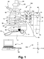
- FIG Figure 1 a laser microdissection system that can be used to carry out a method according to the invention is shown schematically and designated as a whole by 100.
- the laser microdissection system 100 corresponds in essential parts to that in FIG EP 1 276 586 B1 which is expressly incorporated herein by reference.
- the laser microdissection system 100 comprises a microscope 10.
- An illumination device 12 which is only partially shown here, can be provided in a microscope base 11 of the microscope 10. This can include, for example, a light source (not shown) and suitable means for influencing the illuminating light provided by the light source, for example filters and / or diaphragms.
- a condenser unit 90 can be provided for transmitted light illumination and for setting suitable contrast and observation methods.
- the microscope 10 can be designed as a confocal microscope, in particular as a spinning disk microscope, and in this case has corresponding additional or alternative means (in Figure 1 not shown).
- a user input and / or user information unit 13 can also be arranged on the microscope base 11, for example, which can be designed as a touchscreen and via which the user can input and / or read out viewing and / or processing parameters, for example.
- a drive button 14 is also provided. This is used to operate a coarse and a fine drive to adjust the height of a microscope stage 30.
- a sample 51 located in a sample area 50 for example a tissue sample mounted in a corresponding holder, can thereby be brought into an object plane of an objective 41.
- the lens 41 is among others Objectives 42 fastened in an objective nosepiece 40.
- a protective hood 15 can be provided to protect against laser radiation.
- Observation light emanating from the sample 51 runs along an observation beam path a.
- a preferably variable portion of the observation light for example by 60 °, can be decoupled and presented to a user by means of a pair of eyepieces 62.
- a further portion of the observation light can be coupled into a digital image acquisition unit 63 and acquired in an imaging manner.
- the image acquisition unit 63 can be assigned an image evaluation module 64, on site, in a control unit 82 or a control computer 81 (see below), or in another spatial arrangement.
- the laser microdissection system 100 has a laser unit 70 with a laser light source 75.
- a laser beam b provided by the laser light source 75 which can be a UV laser light source, for example, is deflected in a reflected light unit, indicated here as a whole by 76, at a first deflecting mirror 71 and a second deflecting mirror 72 and through the objective 41 focused on the sample 51 in the sample area 50.
- the location at which the laser beam b strikes the sample 51 in the object plane, and thus also in the sample region 50 can in principle be set in different ways.
- a manual adjustment device 31 can be provided, by means of which the microscope stage 30, which is designed as a cross table, can be adjusted in the x and y directions (that is, here perpendicular or parallel to the plane of the paper).
- electromechanical actuating means can also be provided, which can be controlled by a control unit 82 or whose position can be detected by the control unit 82, for example.
- the control unit 82 can also control any further motorized functions of the laser microdissection system 100 and, in particular, provide an interface to an external control computer 81, which can be connected via corresponding connections 83.
- the control unit 82 or the control computer 81 can also evaluate data received by means of the image evaluation module 64, for example. For example, a sequence of tissue layers or other structures of the sample 51 can thereby be recognized.
- the control unit 82 or the Control computer 81 can also be used to control a flushing device, as described in the following Figures 2 and 3 can be used.
- a laser deflection device 73 can be provided for the laser microdissection.
- the laser beam b can be deflected with respect to an optical axis c running between the first deflection mirror 71 and the second deflection mirror 72.
- the laser beam can therefore impinge on the second deflecting mirror 72 at different positions, which mirror can be designed as a dichromatic splitter, for example, and is thus also focused on the sample 51 in the object plane at different positions.
- a deflection by means of a laser deflector 73 is shown in detail in FIG EP 1 276 586 B1 shown. It should be emphasized that different possibilities for deflecting a laser beam b or for positioning the sample 51 in the object plane with respect to the laser beam b can be used. The invention is not restricted to the example shown.
- the laser deflection device 73 has two solid glass wedge plates 731 which are inclined relative to the optical axis c and can be rotated about the optical axis c independently of one another.
- the wedge plates 731 are mounted with ball bearings 732.
- Each of the wedge plates is connected to a gear 733.
- the gears 733 can each be rotated by means of actuators 734, which can be acted upon with corresponding control signals and correspondingly drive the gears 733.
- the rotation devices 734 can have position sensors 735 (shown here only on the right actuator 734). A position detected by the position transmitter 735 can be transmitted to the control unit 82.
- FIG. 10 shows a sample region 50 of a laser microdissection system, for example that of FIG Figure 1 shown laser microdissection system 100, according to an embodiment of the invention in a schematic representation.
- the flushing device provided according to the invention is shown in a preferred embodiment. This is illustrated in a highly schematic manner and in reality includes a large number of other components such as pumps, fluid reservoirs, valves and / or measuring devices.
- Central components of the flushing device are fluid delivery means 55 for providing a suspending fluid in (or on) the sample area 50 and fluid removal means 56 for removing a suspension fluid using the suspending fluid generated suspension from the sample area 50 is provided.
- the fluid delivery means 55 and the fluid removal means 56 are explained in more detail below.
- the sample 51 is arranged on a sample holder 52, for example a slide or a corresponding device with fastening means for fastening the sample 51 and / or fluid guide means.
- the sample holder 52 can also be trough-shaped for fluid guidance and / or have corresponding channels for fluid guidance.
- the sample holder 52 can, for example, be completely flooded with suspending fluid from the fluid delivery means 55.
- the fluid delivery means 55 can also be set up to deliver a defined amount of fluid that does not exceed the capacity or fluid absorption capacity of the sample holder 52.
- the control means 82 and / or the control computer 81 can also be parameterized accordingly, for example.
- the specimen holder 52 can be guided on the specimen table 30 by means of a suitable specimen guide 53 in the x and y directions (cf. also here the coordinate system 200).
- the sample guide 53 and the object table 30 are shown here in a highly schematic manner.
- the sample guide 53 and the object table 30 have suitable adjusting means 54 and 32, respectively.
- the adjusting means 54 and 32 of the sample guide 53 and / or of the specimen table 30 can, for example, also be equipped with an adjusting device 31 (cf., for example, FIG Figure 1 ) can be adjusted and / or controlled by an electric motor.
- At least the object table 30 can, for example by means of a drive knob 14 (see. For example Figure 1 ), can also be adjusted in the z-direction.
- the sample guide 53 can also lie directly on the object table 30.
- the sample guide 53 can also be designed to be movable at least in the x and y directions with respect to the object table 30.
- FIG 2 is also a microscope objective 41 (see. For example Figure 1 ), by means of which the laser beam b is guided into the object region 50.
- the laser beam b strikes the sample 51 at a point of incidence, which is determined by a laser deflection device 73 (cf. for example Figure 1 ) can be set.
- the fluid delivery means 55 can be designed with one or more channels and are designed at least to provide the suspension fluid mentioned several times.
- the fluid delivery means 55 can be coupled to fluid reservoirs and can be controlled, for example, manually and / or by means of a control unit 82 and / or a control computer 81.
- the fluid removal means 56 are designed as a drain in the sample holder 52, but any other arrangement is also possible.
- filter means 561 are provided, by means of which sample particles from a suspension obtained by means of the suspending fluid (cf. in particular Figure 3 ) can be filtered out.
- the filter means 561, or corresponding filters can also be arranged elsewhere or can be omitted (for example when the sample particles are to be obtained by centrifugation).
- the fluid removal means 56 also have suction means 562 for sucking a corresponding suspension out of the sample area 50. These are shown here in simplified form as a line and in practice can be coupled with appropriate pumps, pistons, collecting containers, etc.
- a pressure measuring device 563 is assigned to the fluid extraction means 56, for example, which can be set up to measure a negative pressure in the suction means 562.
- the pressure measuring device 563 can, for example, be equipped with a control device 82 and / or a control computer 81 (cf. for example Figure 1 ) be coupled.
- a control device 82 and / or a control computer 81 cf. for example Figure 1 .
- the fluid extraction means 56 can also be assigned, for example, detector means 564, which can be set up to detect sample particles. This can be provided in particular when no filter means 561 are provided.
- the detector means 564 can include, for example, a light barrier and / or a photosensitive detector and transmit corresponding counting pulses or other data (for example with regard to light scattering) to a control unit 82 and / or a control computer 81.
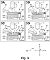
- Figure 3 illustrates a method according to an embodiment of the invention in the form of schematically illustrated method steps as sub-figures 3A to 3D.
- Figure 3 illustrates a method according to an embodiment of the invention in the form of schematically illustrated method steps as sub-figures 3A to 3D.
- a sample 51 which in the example shown has three layers of tissue 511 to 513, is processed by means of the laser beam b.
- the fluid delivery means 55 and the fluid removal means 56 are not in operation in this method step.
- the method step according to FIG. 3A is carried out until, according to FIG. 3B, a depression 514 has been produced in the sample 51 or its uppermost tissue layer 511.
- the laser beam is now switched off.
- Corresponding sample particles 515 are now present in the recess 514 in the sample 51, which are provided with a reference symbol in only one case.
- a suspension fluid 551 for example a suitable buffer, is introduced into the sample area and thus into the depression 514 of the sample 51 by the fluid delivery means 55.
- the sample particles 515 are suspended in the suspending fluid 551 while obtaining a corresponding suspension 552.
- the representation is also greatly simplified here. In reality, for example in an object holder 52 (cf. for example Figure 2 ), as mentioned, appropriate fluid conducting means are provided.
- the suspension 552 obtained can be removed from the sample area parallel or after the suspension fluid 551 has been introduced into the sample area and thus the recess 514 of the sample 51 by means of the fluid extraction means 56, for example by suction. If filter means 561 are provided, the sample particles 515 are deposited thereon. If no filter means 561 are provided, the sample particles 515 can be removed in some other way.
Landscapes
- Physics & Mathematics (AREA)
- Health & Medical Sciences (AREA)
- Life Sciences & Earth Sciences (AREA)
- Chemical & Material Sciences (AREA)
- Analytical Chemistry (AREA)
- Biochemistry (AREA)
- General Health & Medical Sciences (AREA)
- General Physics & Mathematics (AREA)
- Immunology (AREA)
- Pathology (AREA)
- Sampling And Sample Adjustment (AREA)
- Microscoopes, Condenser (AREA)
Claims (11)
- Système de microdissection par laser (100), comprenant un microscope (10) qui présente un dispositif d'éclairage incident (76) muni d'un déflecteur de laser (73) qui guide un faisceau laser fourni par une unité laser (70) à travers un objectif de microscope (41) du microscope (10) sur une zone d'échantillon (50) destinée à recevoir un échantillon biologique (51) et qui déplace un point d'incidence du faisceau laser dans la zone d'échantillon (50),
dans lequel un dispositif de rinçage muni de moyens de distribution de fluide (55) est prévu qui fournit un fluide de suspension (551) dans la zone d'échantillon (50), et des moyens d'extraction de fluide (56) sont disposés sur le dispositif de rinçage et extraient de la zone d'échantillon (50) une suspension (552) produite par l'utilisation du fluide de suspension (551), les moyens d'extraction de fluide (56) comprenant des moyens d'aspiration (562) pour aspirer la suspension (552) à partir de la zone d'échantillon (50),
caractérisé en ce que les moyens d'aspiration (562) comprennent des moyens de collecte de fluide pour collecter la suspension (552) et/ou un fluide dérivé de celle-ci. - Système de microdissection par laser (100) selon la revendication 1, dans lequel les moyens d'extraction de fluide (56) comprennent des moyens de filtrage (561) pour obtenir des particules d'échantillon en suspension (515) à partir de la suspension (552).
- Système de microdissection par laser (100) selon la revendication 2, dans lequel les moyens de filtrage (561) sont reliés aux moyens d'extraction de fluide (56) au moyen d'un raccord rapide.
- Système de microdissection par laser (100) selon la revendication 1, dans lequel le dispositif de rinçage présente au moins un dispositif de mesure de pression (563) et/ou des moyens de réglage pour régler une pression et/ou un débit volumétrique du fluide de suspension (551) et/ou de la suspension (552).
- Système de microdissection par laser (100) selon la revendication 1, dans lequel le dispositif de rinçage présente un dispositif de refroidissement pour refroidir le fluide de suspension et/ou un dispositif d'équilibrage de température pour fournir une température constante du fluide de suspension.
- Système de microdissection par laser (100) selon la revendication 1, dans lequel les moyens d'extraction de fluide comprennent des moyens de détection (564) pour détecter des particules d'échantillon (515) dans la suspension (552).
- Système de microdissection par laser (100) selon la revendication 1, dans lequel les moyens de distribution de fluide (55) sont en outre aménagés pour fournir un fluide de séchage dans la zone d'échantillon (50) .
- Système de microdissection par laser (100) selon la revendication 1, dans lequel le microscope (10) est aménagé pour examiner des structures au-dessous d'une surface de l'échantillon (51).
- Procédé de microdissection par laser permettant d'obtenir de la matière d'échantillon à partir d'un échantillon biologique (51), l'échantillon (51) étant introduit dans une zone d'échantillon (50) d'un système de microdissection par laser (100) qui présente un microscope (10) comprenant un dispositif d'éclairage incident (76) muni d'un déflecteur de laser (73), et dans lequel des particules d'échantillon (515) sont mobilisées à partir de l'échantillon (51) au moyen d'un faisceau laser,
dans lequel un dispositif de rinçage avec des moyens de distribution de fluide (55) et des moyens d'extraction de fluide (56) est utilisé, les moyens de distribution de fluide (55) permettant de fournir un fluide de suspension (551) dans la zone d'échantillon (50), le fluide de suspension (551) permettant de mettre en suspension les particules d'échantillon (515), et une suspension (552) ainsi produite avec les particules d'échantillon (515) étant extraite de la zone d'échantillon (50),
dans lequel le dispositif d'éclairage incident (76) permet de guider un faisceau laser fourni par l'unité laser (70) à travers un objectif de microscope (41) du microscope (10) sur la zone d'échantillon (50) et l'échantillon (51) reçu dans celui-ci et de déplacer le faisceau laser au moyen du déflecteur de laser (73),
caractérisé en ce que les particules d'échantillon (515) sont éliminées de la suspension (552) par filtrage. - Procédé de microdissection par laser selon la revendication 9, dans lequel un échantillon (51) comprenant plusieurs couches de tissu (511, 512, 513) est utilisé, des particules d'échantillon (515) étant obtenues uniquement à partir d'une seule ou d'un certain nombre des couches de tissu (511, 512, 513).
- Procédé de microdissection par laser selon la revendication 9, dans lequel un creux est créé dans l'échantillon (51) au moyen du faisceau laser.
Applications Claiming Priority (2)
| Application Number | Priority Date | Filing Date | Title |
|---|---|---|---|
| DE102013109481.3A DE102013109481A1 (de) | 2013-08-30 | 2013-08-30 | Lasermikrodissektionssystem und Lasermikrodissektionsverfahren |
| PCT/EP2014/067664 WO2015028356A1 (fr) | 2013-08-30 | 2014-08-19 | Système de microdissection par laser et procédé pour système de microdissection par laser |
Publications (2)
| Publication Number | Publication Date |
|---|---|
| EP3039399A1 EP3039399A1 (fr) | 2016-07-06 |
| EP3039399B1 true EP3039399B1 (fr) | 2020-10-07 |
Family
ID=51383724
Family Applications (1)
| Application Number | Title | Priority Date | Filing Date |
|---|---|---|---|
| EP14753071.1A Not-in-force EP3039399B1 (fr) | 2013-08-30 | 2014-08-19 | Système de microdissection par laser et procédé de microdissection par laser |
Country Status (5)
| Country | Link |
|---|---|
| US (1) | US20160202150A1 (fr) |
| EP (1) | EP3039399B1 (fr) |
| JP (1) | JP3207211U (fr) |
| DE (1) | DE102013109481A1 (fr) |
| WO (1) | WO2015028356A1 (fr) |
Families Citing this family (10)
| Publication number | Priority date | Publication date | Assignee | Title |
|---|---|---|---|---|
| JP2019532352A (ja) | 2016-08-28 | 2019-11-07 | オーグメンティクス メディカル リミテッド | 組織標本の組織学的検査のためのシステム |
| DE102016217250A1 (de) * | 2016-09-09 | 2018-03-15 | Fraunhofer-Gesellschaft zur Förderung der angewandten Forschung e.V. | Mikrofluidische Vorrichtung für Zellkulturexperimente und Verwendungen hiervon |
| US11473081B2 (en) | 2016-12-12 | 2022-10-18 | xCella Biosciences, Inc. | Methods and systems for screening using microcapillary arrays |
| US11085039B2 (en) | 2016-12-12 | 2021-08-10 | xCella Biosciences, Inc. | Methods and systems for screening using microcapillary arrays |
| US11156626B2 (en) | 2016-12-30 | 2021-10-26 | xCella Biosciences, Inc. | Multi-stage sample recovery system |
| US10946543B2 (en) * | 2017-10-03 | 2021-03-16 | Agilent Technologies, Inc. | Microtome blade and/or microtome blade holder cleaning using adhesive material |
| EP3890876B1 (fr) | 2018-12-06 | 2024-05-01 | Xcella Biosciences, Inc. | Chargement latéral de réseaux de microcapillaires |
| CN110926851B (zh) * | 2019-11-15 | 2022-03-25 | 华南农业大学 | 一种获取木本植物维管形成层的方法及其应用 |
| EP4232887B1 (fr) * | 2020-12-23 | 2025-03-26 | Leica Biosystems Imaging, Inc. | Dispositif d'entrée à boutons de commande rotatifs |
| CA3251924A1 (fr) * | 2022-05-17 | 2023-11-23 | Keith Louis De Santo | Appareil et procédé de détection de matière et de micro-organismes |
Family Cites Families (11)
| Publication number | Priority date | Publication date | Assignee | Title |
|---|---|---|---|---|
| FR2178555A5 (fr) * | 1972-12-21 | 1973-11-09 | Petroles Cie Francaise | |
| AU4562497A (en) | 1996-10-02 | 1998-04-24 | Cell Robotics, Inc. | Microscope with laser port |
| TW466665B (en) * | 1999-02-05 | 2001-12-01 | Hitachi Ltd | Cleaner of plate part and its method |
| DE10018253C2 (de) | 2000-04-13 | 2003-08-21 | Leica Microsystems | Laser-Mikro-Dissektionsgerät |
| DE10329674B4 (de) * | 2003-06-30 | 2014-08-14 | Karsten König | Laserverfahren und Anordnung zur Markierung und Gewinnung von Materialien, Zellbestandteilen, Zellen und Gewebebestandteilen |
| DE10353985A1 (de) * | 2003-11-19 | 2005-06-23 | Olympus Biosystems Gmbh | Einrichtung und Verfahren zum Manipulieren und Analysieren von Mikroobjekten auf Grundlage eines zumindest bereichsweise als fluidisches Mikrosystem oder/und Chipsystem ausgeführten Mikrosystems |
| WO2006076817A1 (fr) * | 2005-01-21 | 2006-07-27 | Empa, Eidgenössische Materialprüfungs- Und Forschungsanstalt | Analyse d'ablation par laser dans un gaz porteur tournant |
| DE102006035016A1 (de) * | 2006-07-28 | 2008-01-31 | P.A.L.M. Microlaser Technologies Gmbh | Verfahren, Halter und Vorrichtung zum Bearbeiten von biologischen Objekten |
| EP2053377A1 (fr) * | 2007-10-22 | 2009-04-29 | MMI GmbH | Procédé et dispositif destinés à la microdissection tridimensionnelle |
| DE102009016512B4 (de) * | 2009-04-08 | 2011-05-12 | Forschungszentrum Jülich GmbH | Verfahren und Vorrichtung zur Durchführung einer quantitativen ortsaufgelösten Lokal- und Verteilungsanalyse chemischer Elemente und in-situ Charakterisierung der ablatierten Oberflächenregionen |
| US8669118B2 (en) * | 2009-09-11 | 2014-03-11 | Hologic, Inc. | Methods and systems for collecting cells of a biological specimen |
-
2013
- 2013-08-30 DE DE102013109481.3A patent/DE102013109481A1/de not_active Withdrawn
-
2014
- 2014-08-19 EP EP14753071.1A patent/EP3039399B1/fr not_active Not-in-force
- 2014-08-19 WO PCT/EP2014/067664 patent/WO2015028356A1/fr not_active Ceased
- 2014-08-19 JP JP2016600077U patent/JP3207211U/ja not_active Expired - Lifetime
- 2014-08-19 US US14/914,014 patent/US20160202150A1/en not_active Abandoned
Non-Patent Citations (1)
| Title |
|---|
| None * |
Also Published As
| Publication number | Publication date |
|---|---|
| US20160202150A1 (en) | 2016-07-14 |
| JP3207211U (ja) | 2016-11-04 |
| DE102013109481A1 (de) | 2015-03-05 |
| EP3039399A1 (fr) | 2016-07-06 |
| WO2015028356A1 (fr) | 2015-03-05 |
Similar Documents
| Publication | Publication Date | Title |
|---|---|---|
| WO2015028356A1 (fr) | Système de microdissection par laser et procédé pour système de microdissection par laser | |
| EP3017296B1 (fr) | Système de microdissection laser et procédé d'analyse d'échantillons contenant de l'acide nucléique | |
| DE102013209455B4 (de) | Probenfänger zum Auffangen eines Laser-Mikrodissektats | |
| DE102004023262B4 (de) | Verfahren zur Bearbeitung einer Masse mittels Laserbestrahlung und Steuersystem | |
| WO2019063539A1 (fr) | Procédé et dispositif pour l'examen optique d'une pluralité d'échantillons microscopiques | |
| AT507079B1 (de) | Vorrichtung und verfahren zum präparieren von proben | |
| DE102014202860B4 (de) | Bereitstellen von Probeninformationen mit einem Lasermikrodissektionssystem | |
| WO2004019007A1 (fr) | Dispositif support destine a une preparation biologique pouvant etre decoupee par microdissection laser | |
| WO2014191383A1 (fr) | Procédé de microdissection au laser et système de microdissection au laser | |
| EP3921619B1 (fr) | Procédé de microdissection laser | |
| WO2014191451A1 (fr) | Système de microdissection à laser comprenant un dispositif de visualisation et procédé de microdissection à laser | |
| DE102016110750A1 (de) | Trägermembran für die Lasermikrodissektion einer auf die Trägermembran aufgebrachten Probe, Lasermikrodissektionseinrichtung und Lasermikrodissektionsverfahren unter Verwendung einer solchen Trägermembran | |
| DE10329674B4 (de) | Laserverfahren und Anordnung zur Markierung und Gewinnung von Materialien, Zellbestandteilen, Zellen und Gewebebestandteilen | |
| DE102014203656B4 (de) | Lasermikrodissektionsverfahren und Verwendung eines Lasermikrodissektionssystems | |
| DE102015108276B4 (de) | System zur Lasermikrodissektion und Lasermikrodissektionsverfahren | |
| WO2002057746A2 (fr) | Porte-objets, dispositif de microdissection muni d'un porte-objets et procede de microdissection | |
| WO2015128447A1 (fr) | Système et procédé de microdissection laser | |
| EP1367380A1 (fr) | Méthode et dispositif pour la localisation et manipulation automatique de cellules | |
| DE102016111781B3 (de) | Kontaminationsschutzeinrichtung für ein Lasermikrodissektionssystem und Lasermikrodissektionssystem | |
| DE102013227155B4 (de) | Lasermikrodissektionsverfahren und Lasermikrodissektionssystem | |
| DE202007018542U1 (de) | Klimakammer für eine Anordnung zum Untersuchen von mikroskopischen und makroskopischen Präparaten | |
| DE102016105946A1 (de) | Probenbearbeitungsanordnung mit Lasermikrodissektionssystem, Kommunikationseinrichtung und Fertigungssystem | |
| DE202010017281U1 (de) | Probengefäßträger für die Ablage von Einzelzellen unter einem Mikroskop |
Legal Events
| Date | Code | Title | Description |
|---|---|---|---|
| PUAI | Public reference made under article 153(3) epc to a published international application that has entered the european phase |
Free format text: ORIGINAL CODE: 0009012 |
|
| 17P | Request for examination filed |
Effective date: 20160208 |
|
| AK | Designated contracting states |
Kind code of ref document: A1 Designated state(s): AL AT BE BG CH CY CZ DE DK EE ES FI FR GB GR HR HU IE IS IT LI LT LU LV MC MK MT NL NO PL PT RO RS SE SI SK SM TR |
|
| AX | Request for extension of the european patent |
Extension state: BA ME |
|
| RIN1 | Information on inventor provided before grant (corrected) |
Inventor name: SCHLAUDRAFF, FALK |
|
| DAX | Request for extension of the european patent (deleted) | ||
| GRAP | Despatch of communication of intention to grant a patent |
Free format text: ORIGINAL CODE: EPIDOSNIGR1 |
|
| STAA | Information on the status of an ep patent application or granted ep patent |
Free format text: STATUS: GRANT OF PATENT IS INTENDED |
|
| RIC1 | Information provided on ipc code assigned before grant |
Ipc: G01N 1/28 20060101AFI20200219BHEP |
|
| INTG | Intention to grant announced |
Effective date: 20200324 |
|
| GRAS | Grant fee paid |
Free format text: ORIGINAL CODE: EPIDOSNIGR3 |
|
| GRAA | (expected) grant |
Free format text: ORIGINAL CODE: 0009210 |
|
| STAA | Information on the status of an ep patent application or granted ep patent |
Free format text: STATUS: THE PATENT HAS BEEN GRANTED |
|
| AK | Designated contracting states |
Kind code of ref document: B1 Designated state(s): AL AT BE BG CH CY CZ DE DK EE ES FI FR GB GR HR HU IE IS IT LI LT LU LV MC MK MT NL NO PL PT RO RS SE SI SK SM TR |
|
| REG | Reference to a national code |
Ref country code: GB Ref legal event code: FG4D Free format text: NOT ENGLISH |
|
| REG | Reference to a national code |
Ref country code: AT Ref legal event code: REF Ref document number: 1321677 Country of ref document: AT Kind code of ref document: T Effective date: 20201015 Ref country code: CH Ref legal event code: EP |
|
| REG | Reference to a national code |
Ref country code: IE Ref legal event code: FG4D Free format text: LANGUAGE OF EP DOCUMENT: GERMAN |
|
| REG | Reference to a national code |
Ref country code: DE Ref legal event code: R096 Ref document number: 502014014857 Country of ref document: DE |
|
| REG | Reference to a national code |
Ref country code: NL Ref legal event code: MP Effective date: 20201007 |
|
| PG25 | Lapsed in a contracting state [announced via postgrant information from national office to epo] |
Ref country code: GR Free format text: LAPSE BECAUSE OF FAILURE TO SUBMIT A TRANSLATION OF THE DESCRIPTION OR TO PAY THE FEE WITHIN THE PRESCRIBED TIME-LIMIT Effective date: 20210108 Ref country code: FI Free format text: LAPSE BECAUSE OF FAILURE TO SUBMIT A TRANSLATION OF THE DESCRIPTION OR TO PAY THE FEE WITHIN THE PRESCRIBED TIME-LIMIT Effective date: 20201007 Ref country code: RS Free format text: LAPSE BECAUSE OF FAILURE TO SUBMIT A TRANSLATION OF THE DESCRIPTION OR TO PAY THE FEE WITHIN THE PRESCRIBED TIME-LIMIT Effective date: 20201007 Ref country code: NO Free format text: LAPSE BECAUSE OF FAILURE TO SUBMIT A TRANSLATION OF THE DESCRIPTION OR TO PAY THE FEE WITHIN THE PRESCRIBED TIME-LIMIT Effective date: 20210107 Ref country code: PT Free format text: LAPSE BECAUSE OF FAILURE TO SUBMIT A TRANSLATION OF THE DESCRIPTION OR TO PAY THE FEE WITHIN THE PRESCRIBED TIME-LIMIT Effective date: 20210208 Ref country code: NL Free format text: LAPSE BECAUSE OF FAILURE TO SUBMIT A TRANSLATION OF THE DESCRIPTION OR TO PAY THE FEE WITHIN THE PRESCRIBED TIME-LIMIT Effective date: 20201007 |
|
| REG | Reference to a national code |
Ref country code: LT Ref legal event code: MG4D |
|
| PG25 | Lapsed in a contracting state [announced via postgrant information from national office to epo] |
Ref country code: PL Free format text: LAPSE BECAUSE OF FAILURE TO SUBMIT A TRANSLATION OF THE DESCRIPTION OR TO PAY THE FEE WITHIN THE PRESCRIBED TIME-LIMIT Effective date: 20201007 Ref country code: SE Free format text: LAPSE BECAUSE OF FAILURE TO SUBMIT A TRANSLATION OF THE DESCRIPTION OR TO PAY THE FEE WITHIN THE PRESCRIBED TIME-LIMIT Effective date: 20201007 Ref country code: IS Free format text: LAPSE BECAUSE OF FAILURE TO SUBMIT A TRANSLATION OF THE DESCRIPTION OR TO PAY THE FEE WITHIN THE PRESCRIBED TIME-LIMIT Effective date: 20210207 Ref country code: LV Free format text: LAPSE BECAUSE OF FAILURE TO SUBMIT A TRANSLATION OF THE DESCRIPTION OR TO PAY THE FEE WITHIN THE PRESCRIBED TIME-LIMIT Effective date: 20201007 Ref country code: ES Free format text: LAPSE BECAUSE OF FAILURE TO SUBMIT A TRANSLATION OF THE DESCRIPTION OR TO PAY THE FEE WITHIN THE PRESCRIBED TIME-LIMIT Effective date: 20201007 Ref country code: BG Free format text: LAPSE BECAUSE OF FAILURE TO SUBMIT A TRANSLATION OF THE DESCRIPTION OR TO PAY THE FEE WITHIN THE PRESCRIBED TIME-LIMIT Effective date: 20210107 |
|
| PG25 | Lapsed in a contracting state [announced via postgrant information from national office to epo] |
Ref country code: HR Free format text: LAPSE BECAUSE OF FAILURE TO SUBMIT A TRANSLATION OF THE DESCRIPTION OR TO PAY THE FEE WITHIN THE PRESCRIBED TIME-LIMIT Effective date: 20201007 |
|
| REG | Reference to a national code |
Ref country code: DE Ref legal event code: R097 Ref document number: 502014014857 Country of ref document: DE |
|
| PG25 | Lapsed in a contracting state [announced via postgrant information from national office to epo] |
Ref country code: SK Free format text: LAPSE BECAUSE OF FAILURE TO SUBMIT A TRANSLATION OF THE DESCRIPTION OR TO PAY THE FEE WITHIN THE PRESCRIBED TIME-LIMIT Effective date: 20201007 Ref country code: RO Free format text: LAPSE BECAUSE OF FAILURE TO SUBMIT A TRANSLATION OF THE DESCRIPTION OR TO PAY THE FEE WITHIN THE PRESCRIBED TIME-LIMIT Effective date: 20201007 Ref country code: LT Free format text: LAPSE BECAUSE OF FAILURE TO SUBMIT A TRANSLATION OF THE DESCRIPTION OR TO PAY THE FEE WITHIN THE PRESCRIBED TIME-LIMIT Effective date: 20201007 Ref country code: CZ Free format text: LAPSE BECAUSE OF FAILURE TO SUBMIT A TRANSLATION OF THE DESCRIPTION OR TO PAY THE FEE WITHIN THE PRESCRIBED TIME-LIMIT Effective date: 20201007 Ref country code: EE Free format text: LAPSE BECAUSE OF FAILURE TO SUBMIT A TRANSLATION OF THE DESCRIPTION OR TO PAY THE FEE WITHIN THE PRESCRIBED TIME-LIMIT Effective date: 20201007 Ref country code: SM Free format text: LAPSE BECAUSE OF FAILURE TO SUBMIT A TRANSLATION OF THE DESCRIPTION OR TO PAY THE FEE WITHIN THE PRESCRIBED TIME-LIMIT Effective date: 20201007 |
|
| PLBE | No opposition filed within time limit |
Free format text: ORIGINAL CODE: 0009261 |
|
| STAA | Information on the status of an ep patent application or granted ep patent |
Free format text: STATUS: NO OPPOSITION FILED WITHIN TIME LIMIT |
|
| PG25 | Lapsed in a contracting state [announced via postgrant information from national office to epo] |
Ref country code: DK Free format text: LAPSE BECAUSE OF FAILURE TO SUBMIT A TRANSLATION OF THE DESCRIPTION OR TO PAY THE FEE WITHIN THE PRESCRIBED TIME-LIMIT Effective date: 20201007 |
|
| 26N | No opposition filed |
Effective date: 20210708 |
|
| PG25 | Lapsed in a contracting state [announced via postgrant information from national office to epo] |
Ref country code: AL Free format text: LAPSE BECAUSE OF FAILURE TO SUBMIT A TRANSLATION OF THE DESCRIPTION OR TO PAY THE FEE WITHIN THE PRESCRIBED TIME-LIMIT Effective date: 20201007 Ref country code: IT Free format text: LAPSE BECAUSE OF FAILURE TO SUBMIT A TRANSLATION OF THE DESCRIPTION OR TO PAY THE FEE WITHIN THE PRESCRIBED TIME-LIMIT Effective date: 20201007 |
|
| PG25 | Lapsed in a contracting state [announced via postgrant information from national office to epo] |
Ref country code: SI Free format text: LAPSE BECAUSE OF FAILURE TO SUBMIT A TRANSLATION OF THE DESCRIPTION OR TO PAY THE FEE WITHIN THE PRESCRIBED TIME-LIMIT Effective date: 20201007 |
|
| REG | Reference to a national code |
Ref country code: CH Ref legal event code: PL |
|
| PG25 | Lapsed in a contracting state [announced via postgrant information from national office to epo] |
Ref country code: MC Free format text: LAPSE BECAUSE OF FAILURE TO SUBMIT A TRANSLATION OF THE DESCRIPTION OR TO PAY THE FEE WITHIN THE PRESCRIBED TIME-LIMIT Effective date: 20201007 |
|
| REG | Reference to a national code |
Ref country code: BE Ref legal event code: MM Effective date: 20210831 |
|
| PG25 | Lapsed in a contracting state [announced via postgrant information from national office to epo] |
Ref country code: LI Free format text: LAPSE BECAUSE OF NON-PAYMENT OF DUE FEES Effective date: 20210831 Ref country code: CH Free format text: LAPSE BECAUSE OF NON-PAYMENT OF DUE FEES Effective date: 20210831 |
|
| PG25 | Lapsed in a contracting state [announced via postgrant information from national office to epo] |
Ref country code: IS Free format text: LAPSE BECAUSE OF FAILURE TO SUBMIT A TRANSLATION OF THE DESCRIPTION OR TO PAY THE FEE WITHIN THE PRESCRIBED TIME-LIMIT Effective date: 20210207 Ref country code: LU Free format text: LAPSE BECAUSE OF NON-PAYMENT OF DUE FEES Effective date: 20210819 |
|
| PG25 | Lapsed in a contracting state [announced via postgrant information from national office to epo] |
Ref country code: IE Free format text: LAPSE BECAUSE OF NON-PAYMENT OF DUE FEES Effective date: 20210819 Ref country code: BE Free format text: LAPSE BECAUSE OF NON-PAYMENT OF DUE FEES Effective date: 20210831 |
|
| REG | Reference to a national code |
Ref country code: AT Ref legal event code: MM01 Ref document number: 1321677 Country of ref document: AT Kind code of ref document: T Effective date: 20210819 |
|
| PG25 | Lapsed in a contracting state [announced via postgrant information from national office to epo] |
Ref country code: AT Free format text: LAPSE BECAUSE OF NON-PAYMENT OF DUE FEES Effective date: 20210819 |
|
| PG25 | Lapsed in a contracting state [announced via postgrant information from national office to epo] |
Ref country code: HU Free format text: LAPSE BECAUSE OF FAILURE TO SUBMIT A TRANSLATION OF THE DESCRIPTION OR TO PAY THE FEE WITHIN THE PRESCRIBED TIME-LIMIT; INVALID AB INITIO Effective date: 20140819 |
|
| P01 | Opt-out of the competence of the unified patent court (upc) registered |
Effective date: 20230414 |
|
| PG25 | Lapsed in a contracting state [announced via postgrant information from national office to epo] |
Ref country code: CY Free format text: LAPSE BECAUSE OF FAILURE TO SUBMIT A TRANSLATION OF THE DESCRIPTION OR TO PAY THE FEE WITHIN THE PRESCRIBED TIME-LIMIT Effective date: 20201007 |
|
| PGFP | Annual fee paid to national office [announced via postgrant information from national office to epo] |
Ref country code: GB Payment date: 20230822 Year of fee payment: 10 |
|
| PGFP | Annual fee paid to national office [announced via postgrant information from national office to epo] |
Ref country code: FR Payment date: 20230824 Year of fee payment: 10 Ref country code: DE Payment date: 20230828 Year of fee payment: 10 |
|
| PG25 | Lapsed in a contracting state [announced via postgrant information from national office to epo] |
Ref country code: MK Free format text: LAPSE BECAUSE OF FAILURE TO SUBMIT A TRANSLATION OF THE DESCRIPTION OR TO PAY THE FEE WITHIN THE PRESCRIBED TIME-LIMIT Effective date: 20201007 |
|
| PG25 | Lapsed in a contracting state [announced via postgrant information from national office to epo] |
Ref country code: MT Free format text: LAPSE BECAUSE OF FAILURE TO SUBMIT A TRANSLATION OF THE DESCRIPTION OR TO PAY THE FEE WITHIN THE PRESCRIBED TIME-LIMIT Effective date: 20201007 |
|
| REG | Reference to a national code |
Ref country code: DE Ref legal event code: R119 Ref document number: 502014014857 Country of ref document: DE |
|
| GBPC | Gb: european patent ceased through non-payment of renewal fee |
Effective date: 20240819 |
|
| PG25 | Lapsed in a contracting state [announced via postgrant information from national office to epo] |
Ref country code: DE Free format text: LAPSE BECAUSE OF NON-PAYMENT OF DUE FEES Effective date: 20250301 |
|
| PG25 | Lapsed in a contracting state [announced via postgrant information from national office to epo] |
Ref country code: GB Free format text: LAPSE BECAUSE OF NON-PAYMENT OF DUE FEES Effective date: 20240819 |
|
| PG25 | Lapsed in a contracting state [announced via postgrant information from national office to epo] |
Ref country code: FR Free format text: LAPSE BECAUSE OF NON-PAYMENT OF DUE FEES Effective date: 20240831 |
|
| PG25 | Lapsed in a contracting state [announced via postgrant information from national office to epo] |
Ref country code: TR Free format text: LAPSE BECAUSE OF FAILURE TO SUBMIT A TRANSLATION OF THE DESCRIPTION OR TO PAY THE FEE WITHIN THE PRESCRIBED TIME-LIMIT Effective date: 20201007 |