EP2053398A1 - Verfahren zur bestätigung der leistung eines optischen detektors und referenzreagenz dafür - Google Patents
Verfahren zur bestätigung der leistung eines optischen detektors und referenzreagenz dafürInfo
- Publication number
- EP2053398A1 EP2053398A1 EP07860071A EP07860071A EP2053398A1 EP 2053398 A1 EP2053398 A1 EP 2053398A1 EP 07860071 A EP07860071 A EP 07860071A EP 07860071 A EP07860071 A EP 07860071A EP 2053398 A1 EP2053398 A1 EP 2053398A1
- Authority
- EP
- European Patent Office
- Prior art keywords
- optical signal
- performance
- temperature
- standard sample
- nucleic acid
- Prior art date
- Legal status (The legal status is an assumption and is not a legal conclusion. Google has not performed a legal analysis and makes no representation as to the accuracy of the status listed.)
- Granted
Links
Images
Classifications
-
- G—PHYSICS
- G01—MEASURING; TESTING
- G01N—INVESTIGATING OR ANALYSING MATERIALS BY DETERMINING THEIR CHEMICAL OR PHYSICAL PROPERTIES
- G01N21/00—Investigating or analysing materials by the use of optical means, i.e. using sub-millimetre waves, infrared, visible or ultraviolet light
- G01N21/17—Systems in which incident light is modified in accordance with the properties of the material investigated
- G01N21/25—Colour; Spectral properties, i.e. comparison of effect of material on the light at two or more different wavelengths or wavelength bands
- G01N21/27—Colour; Spectral properties, i.e. comparison of effect of material on the light at two or more different wavelengths or wavelength bands using photo-electric detection ; circuits for computing concentration
- G01N21/274—Calibration, base line adjustment, drift correction
-
- C—CHEMISTRY; METALLURGY
- C12—BIOCHEMISTRY; BEER; SPIRITS; WINE; VINEGAR; MICROBIOLOGY; ENZYMOLOGY; MUTATION OR GENETIC ENGINEERING
- C12Q—MEASURING OR TESTING PROCESSES INVOLVING ENZYMES, NUCLEIC ACIDS OR MICROORGANISMS; COMPOSITIONS OR TEST PAPERS THEREFOR; PROCESSES OF PREPARING SUCH COMPOSITIONS; CONDITION-RESPONSIVE CONTROL IN MICROBIOLOGICAL OR ENZYMOLOGICAL PROCESSES
- C12Q1/00—Measuring or testing processes involving enzymes, nucleic acids or microorganisms; Compositions therefor; Processes of preparing such compositions
- C12Q1/68—Measuring or testing processes involving enzymes, nucleic acids or microorganisms; Compositions therefor; Processes of preparing such compositions involving nucleic acids
- C12Q1/6813—Hybridisation assays
- C12Q1/6816—Hybridisation assays characterised by the detection means
-
- C—CHEMISTRY; METALLURGY
- C12—BIOCHEMISTRY; BEER; SPIRITS; WINE; VINEGAR; MICROBIOLOGY; ENZYMOLOGY; MUTATION OR GENETIC ENGINEERING
- C12Q—MEASURING OR TESTING PROCESSES INVOLVING ENZYMES, NUCLEIC ACIDS OR MICROORGANISMS; COMPOSITIONS OR TEST PAPERS THEREFOR; PROCESSES OF PREPARING SUCH COMPOSITIONS; CONDITION-RESPONSIVE CONTROL IN MICROBIOLOGICAL OR ENZYMOLOGICAL PROCESSES
- C12Q1/00—Measuring or testing processes involving enzymes, nucleic acids or microorganisms; Compositions therefor; Processes of preparing such compositions
- C12Q1/68—Measuring or testing processes involving enzymes, nucleic acids or microorganisms; Compositions therefor; Processes of preparing such compositions involving nucleic acids
- C12Q1/6844—Nucleic acid amplification reactions
- C12Q1/6848—Nucleic acid amplification reactions characterised by the means for preventing contamination or increasing the specificity or sensitivity of an amplification reaction
-
- G—PHYSICS
- G01—MEASURING; TESTING
- G01N—INVESTIGATING OR ANALYSING MATERIALS BY DETERMINING THEIR CHEMICAL OR PHYSICAL PROPERTIES
- G01N21/00—Investigating or analysing materials by the use of optical means, i.e. using sub-millimetre waves, infrared, visible or ultraviolet light
- G01N21/62—Systems in which the material investigated is excited whereby it emits light or causes a change in wavelength of the incident light
Definitions
- the present invention relates to a method of verifying the optical signal detection performance and the temperature control performance of an optical detection apparatus in order to verify whether detection of an optical signal of a sample and control of temperature of the sample are performed normally, and to a standard reagent used therefor.
- Tm melting temperature
- the Tm value is defined as follows. When a solution containing a double-stranded nucleic acid is heated, the absorbance at 260 nm increases. This is because heating releases the hydrogen bonds between both of the strands in the double-stranded nucleic acid to dissociate it into a single-stranded nucleic acid (i.e. to melt the nucleic acid). When all double-stranded nucleic acids are dissociated into single-stranded DNAs, the absorbance thereof is approximately 1.5 times that obtained at the start of heating (i.e. the absorbance of only double-stranded nucleic acids), which makes it possible to judge that melting is completed thereby. Based on this phenomenon, the melting temperature Tm (°C) generally is defined as a temperature at which the absorbance has reached 50% of the total increase in absorbance.
- nucleic acid makes it possible to detect, for example, a polymorphism or a mutation at a target site as follows. That is, the following method is used. First, a mutant-type detection probe complementary to a target nucleic acid sequence containing a mutant-type target site is used to form a double-stranded nucleic acid between the aforementioned probe and a single-stranded nucleic acid to be analyzed. The double-stranded nucleic acid thus formed is then heat-treated, and signals indicating dissociation (melting) of the double-stranded nucleic acid accompanying the temperature rise are measured.
- the Tm value is determined from the behavior of the signal values thus measured, and from the Tm value thus determined, the presence or absence of a mutation at the target site is judged (see Nonpatent Document 1 and Patent Document 1).
- the Tm value to serve as an assessment criterion is determined beforehand with respect to each of the double-stranded nucleic acid formed of a target nucleic acid sequence containing a mutant-type target site and a mutant-type detection probe that is 100% complementary thereto and the double-stranded nucleic acid formed of a nucleic acid sequence with a wild-type target site and the mutant-type detection probe.
- the higher the homology the higher the Tm value. Accordingly, the Tm value (hereinafter also referred to as the "Tm m value”) obtained in the case of the former, i.e.
- the Tm value (hereinafter also referred to as the "Tm w value") obtained in the case of the latter, i.e. in the case where the target site is a wild type, is relatively low.
- Tm w value the Tm value obtained in the case of the latter, i.e. in the case where the target site is a wild type.
- the polymorphism at the target site is a mutant form.
- the Tm value indicating the peak is lower than the Tm m value determined beforehand and is comparable to the Tm W value, the single-stranded nucleic acid and the probe are mismatched by a single base. Accordingly, it can be judged that in the nucleic acid to be analyzed, the polymorphism at the target site is a wild type. Furthermore, it also can be judged whether the polymorphism is a homozygote or a heterozygote.
- an optical detection apparatus that includes a detection unit for detecting the optical signal of a sample and a temperature control unit for controlling the temperature of the sample, and various such products are on the market.
- the Tm value is determined by measuring the change in optical signal accompanying a change in the temperature
- two points i.e. whether the temperature of the sample is controlled accurately inside the optical detection apparatus and whether the optical signal of the sample is detected normally.
- it is indispensable to verify both the optical signal detection performance and the temperature control performance in order to maintain the reliability of the analysis results. Therefore, in the case of optical signal detection, for example, a solution containing a known fluorescent material at a known concentration is provided and the signal intensity (fluorescence intensity) of the fluorescent dye in the solution then is measured under a predetermined temperature condition, and thereby it is verified whether the optical signal can be measured normally.
- sample placement part a predetermined part of the optical detection apparatus and the temperature of the sample then is measured actually.
- sample placement part a predetermined part of the optical detection apparatus
- the temperature of the sample placed in the optical detection apparatus is measured usually with a thermometer introduced from the outside.
- a thermometer introduced from the outside.
- the temperature may vary depending on the place where the measurement is carried out in the sample placement part.
- the sample placement part is minute, there is a possibility that the introduction itself of the thermometer from the outside may affect the actual temperature. For such reasons, it is difficult to measure the actual temperature of a sample placed in the optical detection apparatus accurately. Consequently, it is difficult to judge whether the temperature of the sample is controlled accurately by the temperature control unit.
- the present invention therefore is intended to provide a method that makes it possible to verify whether optical signal detection and temperature control are performed accurately, i.e. the performances thereof, simply and with high reliability, with respect to an optical detection apparatus including an optical detection unit and a temperature control unit.
- a method of verifying the performance of an optical detection apparatus of the present invention is a method of verifying the optical signal detection performance of a detection unit for detecting an optical signal of a sample and the temperature control performance of a temperature control unit for controlling temperature of the sample, in an optical detection apparatus equipped with the detection unit and the temperature control unit, wherein the method includes the following steps (A) to (D):
- a manufacturing method of the present invention is a method of manufacturing an optical detection apparatus equipped with a detection unit for detecting an optical signal of a sample and a temperature control unit for controlling temperature of the sample, wherein the manufacturing method includes a step of verifying the optical signal detection performance of the detection unit and the temperature control performance of the temperature control unit by a method of verifying the performance of the present invention.
- a standard reagent of the present invention is used in a method of verifying the performance of an optical detection apparatus of the present invention, wherein the standard reagent contains a nucleic acid sequence and a strand complementary thereto that have a known optical signal intensity and melting temperature.
- the Tm analysis that is performed with the aforementioned standard sample is carried out using an optical detection apparatus to be evaluated and thereby both the detection unit performance and the temperature control unit performance can be verified.
- the measurement results of the standard sample are compared to the known conditions (the signal intensity and Tm value) of the standard sample. For example, when they are approximately identical to each other, it can be judged that the performances of the detection unit and the temperature control unit are normal, while it can be judged that the performances are abnormal when they are different from each other.
- the present invention is a technique utilizing the characteristics that a double strand is formed of (hybridized from) nucleic acid and a strand complementary thereto and the double strand is dissociated (dissociated into a single-stranded nucleic acid) by a heat treatment, and they have inherent Tm values (°C) according to the sequences thereof.
- Tm values °C
- the method of verifying the performance of the present invention also can be used for a performance testing step in manufacturing an optical detection apparatus.
- the method of verifying the performance of the present invention can be considered to be a very effective technique since it allows both the optical signal detection performance and temperature control performance of an optical detection apparatus to be verified easily and simply by the same method.
- a method of verifying the performance of an optical detection apparatus of the present invention is a method of verifying the optical signal detection performance of a detection unit for detecting an optical signal of a sample and the temperature control performance of a temperature control unit for controlling temperature of the sample, in an optical detection apparatus equipped with the detection unit and the temperature control unit, wherein the method includes the following steps (A) to (D):
- the combination of a nucleic acid sequence and a strand complementary thereto contained in the standard sample is not limited, as long as it allows formation of a hybrid (formation of a double-stranded nucleic acid) and dissociation of the hybrid (dissociation into a single-stranded nucleic acid) to occur according to a change in the temperature.
- the Tm value of a double-stranded nucleic acid formed through hybridization of the nucleic acid sequence and the complementary strand is necessary.
- a theoretical value can be calculated by a conventionally known method based on, for example, sequence information, GC content, salt concentration, etc.
- the known method examples include a nearest neighbor method and a method using the software MeltCalc (http://www.meltcalc.de/).
- the theoretical value of the Tm value can be used as, for example, a "known Tm value".
- the Tm value may be affected by, for example, not only the salt concentration in a reaction solution but also the concentrations of the nucleic acid sequence and the strand complementary thereto as well as the presence of a conjugate group (for instance, biotin or a fluorescent dye). Therefore, it is preferable that, for example, using a reaction solution containing a standard sample, a Tm value be measured beforehand with an optical detection apparatus whose detection performance and temperature control performance are normal, and it be used as the known Tm value.
- a nucleic acid sequence and a strand complementary thereto that have an already known Tm value may be used in combination.
- the nucleic acid sequence and the strand complementary thereto are not limited as long as they are allowed to undergo hybridization and dissociation according to a change in the temperature. Therefore, the complementary strand may be, for example, a sequence that is completely (100%) complementary to the nucleic acid sequence or a sequence that is partially different therefrom. Moreover, the complementary strand may be, for example, a strand composed only of a sequence complementary to the nucleic acid sequence, a strand including a sequence complementary to the nucleic acid sequence, or a strand composed only of a sequence complementary to a partial sequence of the nucleic acid sequence.
- nucleic acid sequence and the complementary strand examples include polynucleotides. Each length thereof is not particularly limited but is preferably, for example, approximately 10- to 100-mers.
- the nucleic acid sequence and the complementary strand that are contained in the standard sample may be in a state in which they have been hybridized (double-stranded nucleic acid) or in a state where they have been dissociated.
- a preferable specific example of the combination of the nucleic acid sequence and the complementary strand is, for example, a combination of a probe labeled with a labeling substance that emits an optical signal (hereinafter also referred to as a "labeled probe") and a strand complementary thereto because it can improve the optical signal detection sensitivity.
- the labeled probe include a labeled probe that exhibits a signal independently and does not exhibit a signal after being hybridized and one that does not exhibit a signal independently and exhibits a signal after being hybridized.
- the former probe does not exhibit a signal after forming a hybrid (double strand) with a complementary strand but exhibits a signal when the hybrid is dissociated by heating and thereby the labeled probe is released.
- the latter probe exhibits a signal after forming a hybrid (double strand) with a complementary strand but the signal is reduced (quenched) when the hybrid is dissociated by heating and thereby the labeled probe is released.
- an optical signal may be measured in step (B), for example, under conditions determined according to the type of the labeling substance.
- the method of measuring an optical signal in step (B) can be determined suitably, for example, according to the type of the labeling substance and is not particularly limited. Examples thereof include absorbance (absorption intensity) measurement and fluorescence intensity measurement.
- the progress of melting and the Tm value can be determined by using the labeled probe and measuring a signal of the labeling substance, as in the case of the measurement of absorbance at 260 nm that indicates the melting state of the double-stranded nucleic acid (unlabeled). Since the present invention is a method of verifying the performance of an optical detection apparatus, it is particularly preferable that when the labeled probe is used, for example, the optical signal detection performance be verified using a labeling substance that is assumed to be measured with the optical detection apparatus (labeling substance to be measured).
- the labeling substance is not particularly limited as described above but is preferably a fluorescent material because it is used widely.
- examples thereof include a fluorescent dye (fluorophore).
- a specific example thereof is preferably a probe that, for example, exhibits fluorescence independently and allows fluorescence to be reduced (for example, quenched) after being hybridized.
- a probe that utilizes such a fluorescence quenching phenomenon is referred to as a fluorescence quenching probe.
- the base located at the end to be labeled or a base adjacent thereto be cytosine (C).
- the adjacent base is preferably, for example, a base located first to third counted from the base located at the end.
- the base sequences of the labeled probe and complementary strand be designed so that the base to be paired with the end base C of the labeled probe or the adjacent base C be G.
- such a probe is referred to as a guanine quenching probe and is known as so-called QProbe (registered trademark).
- the fluorescent dye is not particularly limited. Examples thereof include a fluorescein, phosphor, rhodamine, and polymethine dye derivative.
- Examples of commercially available fluorescent dyes include BODIPY FL (brand name, manufactured by Molecular Probe Inc.), FluorePrime (trade name, manufactured by Amersham Pharmacia), Fluoredite (trade name, manufactured by Millipore Corporation), FAM (manufactured by ABI), Cy3 and Cy5 (manufactured by Amersham Pharmacia), and TAMRA (manufactured by Molecular Probe Inc.).
- the combination of the nucleic acid sequence and the complementary strand may be, for example, a combination of an unlabeled nucleic acid sequence and a nucleic acid sequence complementary thereto.
- a double-stranded nucleic acid changes in absorbance at a wavelength of 260 nm according to a change in temperature.
- the absorbance at 200 to 350 nm preferably, 260 nm
- the lengths of such a nucleic acid sequence and a complementary strand also are not particularly limited and are the same as described above.
- the standard sample additionally may contain, for example, an intercalator.
- an intercalator is preferably, for example, an intercalating fluorescent material, which generally is known as a dye whose fluorescence properties change through intercalation into a double-stranded nucleic acid.
- a fluorescent dye is not particularly limited as long as the fluorescence properties thereof change through intercalation into a double-stranded nucleic acid.
- a fluorescent dye whose fluorescence intensity increases through intercalation is preferable.
- the standard sample in the case of a standard sample containing the intercalator, can be irradiated with excitation light and thereby the intensity of fluorescence generated from the intercalator may be measured in step (B) described above.
- performance verification may be carried out twice or more.
- a hybrid formed of a nucleic acid sequence and a complementary strand has an inherent Tm value. Accordingly, when a plurality of standard samples whose Tm values are different from each other are used, it can be evaluated with respect to each of the samples whether temperature control and optical signal detection are being performed accurately. This allows the performance to be verified over more temperature ranges. Consequently, the reliability of analysis that is performed using an optical detection apparatus can be further improved.
- performance verification may be carried out using two or more standard samples that are different only in the type of the labeling substance contained in the labeled probe. For instance, when two or more fluorescent materials that are different in detection wavelength are used in actual measurement carried out using optical detection, fluorescence intensities are detected at two or more different wavelengths in one optical detection apparatus. In such a case, when the performance of a fluorescence detection apparatus is verified beforehand using two or more standard samples that are different in fluorescent material, it also is possible to perform measurement with high reliability with respect to, for example, a plurality of wavelengths.
- the analysis can be performed with very high reliability.
- the type of optical signal is not particularly limited.
- it can be fluorescence intensity or absorbance according to the presence or absence of labeling of the nucleic acid sequence or the presence or absence of intercalation.
- An optical detection apparatus that can employ the method of verifying the performance of the present invention is not limited as long as it is an apparatus equipped with an optical detection unit for detecting an optical signal of a sample and a temperature control unit, and, for example, configurations, sizes, placement parts, and other constitutions of the respect units are not limited.
- the method of verifying the performance of the present invention is applicable to conventionally known optical detection apparatuses such as a Tm analyzer, a PCR (polymerase chain reaction) system, and a real-time PCR system.
- the method of verifying the performance of the present invention is described with an example using a standard sample containing a labeled probe that has been labeled with a fluorescent dye and a strand complementary thereto.
- the present invention is not limited by this example.
- a standard sample containing a labeled probe and a strand complementary thereto as described above is provided. Since a liquid sample is used generally for the Tm analysis, the standard sample is preferably a liquid containing the labeled probe and the complementary strand.
- the solvent for the standard sample is not limited. Examples thereof include various buffer solutions such as water, glycine, citric acid, acetic acid, phosphoric acid, and Tris, and the pH thereof is preferably in the range of, for example, 5 to 9. In addition, for example, salt, alcohol, or a surfactant may be contained.
- the Tm value (known Tm value) of the hybrid between the labeled probe and the complementary strand in the standard sample can be determined beforehand by the method as described above.
- the known optical signal intensity of the standard sample can be set, for example, as follows. For example, using an optical detection apparatus in which the detection performance of an optical detection unit and temperature control performance are normal, the optical signal intensity of the standard sample is measured beforehand under the same conditions as those employed for the performance verification described later. This is used as the known optical signal intensity.
- a probe labeled with a fluorescent dye for example, the composition of the standard sample, the type of the fluorescent dye, the concentration of the labeled probe and complementary strand in the standard sample, the sequences of the labeled probe and complementary strand, the type of the light source for excitation light (for instance, wavelength or the amount of light), the type of detection (for instance, wavelength or detection sensitivity), and the detection temperature are specified, and fluorescent signal intensity then is measured.
- This measured value can be used as a known fluorescent signal intensity.
- the fluorescent signal intensity of the standard sample is measured with an apparatus whose performance is to be verified under the same measurement conditions as those employed for determining the known fluorescent signal intensity.
- the detection performance can be verified by comparing this measured value to the known fluorescent signal intensity and judging whether they are comparable to each other. As described above, when verification measurement is carried out using an identical standard sample under the same conditions, it also is possible to verify the optical detection unit performance continually with high reliability in the case where, for example, the performance is verified periodically.
- sample placement unit sample placement unit
- apparatus optical detection apparatus
- the temperature of the standard sample placed inside the apparatus is increased or decreased according to the method of operating the optical detection apparatus.
- the initial temperature and the final temperature are not particularly limited and can be determined according to, for example, the known Tm value of the standard sample to be employed.
- the nucleic acid sequence and the complementary strand are in the form of a hybrid. Therefore, it is preferable that, for example, the temperature of the standard sample be increased to a higher temperature than the known Tm value over time to dissociate the hybrid.
- the temperature of the standard sample be decreased to a lower temperature than the known Tm value over time to allow a hybrid to be formed.
- the fluorescence intensity of the standard sample accompanying a change in the temperature is measured according to the method of operating the optical detection apparatus.
- the fluorescence intensity may be measured, for example, continuously or intermittently. However, since the present invention is intended to verify the performance, continuous measurement is preferable.
- the melting temperature of the standard sample is determined from the change in fluorescence intensity accompanying the change in temperature measured in step (B). Specifically, for example, from the measurement result of the change in fluorescence intensity, the Tm value (Tm 1 ) is determined based thereon.
- the Tm value (Tm 1 ) can be determined from, for example, the amount of change in optical signal intensity per unit time. Specifically, for example, the amount of change in optical signal intensity per unit time at each temperature is determined first from the optical signal intensity of the standard sample measured in step (B). This amount of change can be calculated by, for example, the formula "-d amount of change in fluorescence intensity/dt" or "amount of change in fluorescence intensity/dt". The point (temperature) at which the absolute value of the amount of change in optical signal intensity is the largest value can be determined as the Tm value (Tm 1 ) of the standard sample. However, the present invention is not limited by this.
- Tm value thus determined and the fluorescence intensity of the standard sample thus measured are compared to the known Tm value (Tm 0 ) and the known fluorescence intensity (F 0 ) of the standard sample, respectively.
- Tm 0 known Tm value
- F 0 known fluorescence intensity
- the detection performance of the optical detection unit and the temperature control performance of the temperature control unit of the optical detection apparatus can be judged to be normal.
- Tm ⁇ Tm 1 and F 0 ⁇ F 1 the detection performance of the optical detection unit and the temperature control performance of the temperature control unit of the optical detection apparatus can be judged to be abnormal.
- the extent of approximation of the measured results Tm 1 and F 1 to the known values Tm 0 and F 0 that is judged to be normal and the extent of difference therebetween that is judged to be abnormal are not limited.
- the present invention is characterized in that it was found that the performance was verifiable by the Tm analysis.
- the criterion (reference for evaluation) for determining whether the performance is normal or abnormal can be set to a desired criterion by the person who verifies the optical detection apparatus.
- the known signal intensity of the standard sample may be, for example, the amount of change in optical signal intensity per unit time at a desired temperature.
- step (D) the amount of change in optical signal intensity per unit time at a desired temperature is determined from the optical signal intensity of the standard sample measured in step (B), and then is compared to the known amount of change in optical signal intensity per unit time at the desired temperature of the standard sample.
- the amount of change in fluorescence intensity per unit time at the desired temperature can be determined by the formula "-d amount of change in fluorescence intensity/dt" or "amount of change in fluorescence intensity/dt" from the measured fluorescence intensity.
- the manufacturing method of the present invention is a method of manufacturing an optical detection apparatus equipped with a detection unit for detecting an optical signal of a sample and a temperature control unit for controlling temperature of the sample, wherein the manufacturing method includes verifying the optical signal detection performance of the detection unit and temperature control performance of the temperature control unit by a method of verifying the performance of the present invention.
- the present invention is characterized by verifying the optical detection apparatus performance relating to manufacture according to the method of verifying the performance of the present invention as part of the manufacturing process, and the other configurations or conditions are not limited.
- a standard reagent of the present invention is used for verifying the optical signal detection performance of an optical detection unit for detecting an optical signal of a sample and temperature control performance of a temperature control unit for controlling temperature of the sample in an optical detection apparatus equipped with the optical detection unit and the temperature control unit, wherein the standard reagent contains a nucleic acid sequence and a strand complementary thereto that have a known optical signal intensity and Tm value.
- the standard reagent of the present invention can be used as a standard sample in the method of verifying the performance of the present invention.
- the above-mentioned nucleic acid sequence and the strand complementary thereto are the same as described above.
- the composition of the standard reagent and the method of using it are the same as those employed for the standard sample.
- reaction solution having the composition described below was provided as a standard sample (standard reagent), with the reaction solution containing the labeled probe described below and a complementary strand DNA that is complementary thereto.
- the (BODIPY FL) located at the 5' end of the labeled probe described below is a fluorescent dye and the (P) located at the 3' end denotes phosphorylation.
- Distilled water 19.5 10 ⁇ Gene Taq buffer * 2.5 5 ⁇ M labeled probe 1.0 5 ⁇ M Complementary strand DNA 2.0 Total 25.0 ⁇ L * Trade name, Gene Taq Fp: manufactured by Nippon Gene Co., Ltd.
- the known Tm value and known fluorescence intensity of the reaction solution were determined beforehand as follows.
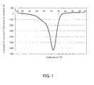
- An optical detection apparatus (trade name: Smart Cycler, manufactured by Cepheid) was prepared, which was of the same type as the fluorescence detection apparatus whose performance was to be evaluated, which is described later, and it was confirmed beforehand that the optical detection apparatus had a normal detection performance of the optical detection unit and a normal temperature control performance. Thereafter, using this optical detection apparatus, the fluorescence values (fluorescence intensities) in the predetermined temperature range (45 ⁇ 95°C) were measured under the same conditions as those employed for performance verification described later. From the fluorescence values, the differential value "-d amount of increase in fluorescence intensity/dt" was determined that indicated the amount of change in fluorescence intensity.
- the Tm value of the reaction solution was 70.6°C and the fluorescence value at 80°C was 1072, which were used as the known Tm value and known fluorescence intensity, respectively.
- any fluorescence value obtained at any temperature can be used as the known fluorescence intensity.
- the fluorescence values (known fluorescence intensities) obtained at a plurality of temperatures are indicated as examples in Table 2 below.
- FIG. 1 is a graph of Tm analysis showing the change in fluorescence intensity accompanying the temperature rise, and the differential value indicated on the vertical axis denotes "-d amount of increase in fluorescence intensity/dt".
- the temperature at which the peak differential value of the fluorescence intensity was obtained was 70.6°C and was comparable to the known Tm value, 70.9°C. Furthermore, the fluorescence value at 80°C was 984 and was almost comparable to the known fluorescence value, 1072.
- the above-mentioned results proved that there was no problem in either the fluorescence intensity detection performance or the temperature control performance.
- the method according to this example allows both the fluorescence intensity detection performance and the temperature control performance to be verified from the result of single Tm analysis.
- the method of the present invention allows both the optical detection unit performance and the temperature control unit performance to be verified by carrying out Tm analysis with an optical detection apparatus whose performance is to be evaluated, using a standard sample. Specifically, the measurement results of a standard sample are compared to known conditions (intensity and Tm value) of the standard sample, and thereby it can be judged that, for example, the optical detection apparatus performance is accurate if they are almost comparable to each other, and the performance is inaccurate if they are different from each other. Furthermore, according to the method of the present invention, there is no need to introduce, for example, a thermometer from the outside for the temperature measurement as in the conventional case. Thus, the method of verifying the performance of the present invention allows both the optical signal detection performance and temperature control performance of an optical detection apparatus to be verified easily and simply by the same method. Thus, it is very effective technique.
Landscapes
- Chemical & Material Sciences (AREA)
- Life Sciences & Earth Sciences (AREA)
- Organic Chemistry (AREA)
- Health & Medical Sciences (AREA)
- Physics & Mathematics (AREA)
- Engineering & Computer Science (AREA)
- Wood Science & Technology (AREA)
- Proteomics, Peptides & Aminoacids (AREA)
- Zoology (AREA)
- Analytical Chemistry (AREA)
- Biochemistry (AREA)
- General Health & Medical Sciences (AREA)
- Immunology (AREA)
- Genetics & Genomics (AREA)
- Chemical Kinetics & Catalysis (AREA)
- Biophysics (AREA)
- General Engineering & Computer Science (AREA)
- Biotechnology (AREA)
- Microbiology (AREA)
- Molecular Biology (AREA)
- Bioinformatics & Cheminformatics (AREA)
- General Physics & Mathematics (AREA)
- Pathology (AREA)
- Mathematical Physics (AREA)
- Theoretical Computer Science (AREA)
- Spectroscopy & Molecular Physics (AREA)
- Nuclear Medicine, Radiotherapy & Molecular Imaging (AREA)
- Measuring Or Testing Involving Enzymes Or Micro-Organisms (AREA)
- Investigating, Analyzing Materials By Fluorescence Or Luminescence (AREA)
- Investigating Or Analysing Materials By The Use Of Chemical Reactions (AREA)
- Apparatus Associated With Microorganisms And Enzymes (AREA)
Applications Claiming Priority (2)
| Application Number | Priority Date | Filing Date | Title |
|---|---|---|---|
| JP2007002405 | 2007-01-10 | ||
| PCT/JP2007/074842 WO2008084672A1 (ja) | 2007-01-10 | 2007-12-25 | 光学検出装置の性能確認方法およびそれに用いる標準試薬 |
Publications (3)
| Publication Number | Publication Date |
|---|---|
| EP2053398A1 true EP2053398A1 (de) | 2009-04-29 |
| EP2053398A4 EP2053398A4 (de) | 2010-07-14 |
| EP2053398B1 EP2053398B1 (de) | 2012-05-16 |
Family
ID=39608568
Family Applications (1)
| Application Number | Title | Priority Date | Filing Date |
|---|---|---|---|
| EP07860071A Active EP2053398B1 (de) | 2007-01-10 | 2007-12-25 | Verfahren zur bestätigung der leistung eines optischen detektors und referenzreagenz dafür |
Country Status (6)
| Country | Link |
|---|---|
| US (1) | US8637238B2 (de) |
| EP (1) | EP2053398B1 (de) |
| JP (1) | JP5255439B2 (de) |
| KR (2) | KR20110117208A (de) |
| CN (1) | CN101501496B (de) |
| WO (1) | WO2008084672A1 (de) |
Cited By (1)
| Publication number | Priority date | Publication date | Assignee | Title |
|---|---|---|---|---|
| WO2012031050A1 (en) | 2010-08-31 | 2012-03-08 | Canon U.S. Life Sciences, Inc. | Thermal calibration |
Families Citing this family (7)
| Publication number | Priority date | Publication date | Assignee | Title |
|---|---|---|---|---|
| KR20120068992A (ko) * | 2009-10-30 | 2012-06-27 | 아크레이 가부시키가이샤 | Mpl 유전자 다형 검출용 프로브 및 그 용도 |
| CN102317454A (zh) * | 2009-12-07 | 2012-01-11 | 爱科来株式会社 | 疾病相关基因的多态性检测用探针及其用途 |
| JP5853494B2 (ja) * | 2011-08-25 | 2016-02-09 | セイコーエプソン株式会社 | 熱サイクル装置及び異常判定方法 |
| DE112014003484B4 (de) * | 2013-08-27 | 2023-03-02 | Hitachi High-Tech Corporation | Nucleinsäure-Analysenvorrichtung und Nucleinsäure-Diagnoseverfahren |
| CN103472218B (zh) * | 2013-09-27 | 2015-05-27 | 智锐达仪器科技南通有限公司 | 一种胶体金读卡仪及相应的控制方法 |
| CN104698488B (zh) * | 2013-12-10 | 2018-01-09 | 北京瑞利分析仪器有限公司 | 一种探测气体传输管路中液体和泡沫的装置及系统 |
| CN104502338B (zh) * | 2014-12-29 | 2017-04-26 | 厦门安东电子有限公司 | 一种农药残留辅助检测装置和检测方法 |
Family Cites Families (7)
| Publication number | Priority date | Publication date | Assignee | Title |
|---|---|---|---|---|
| JP3785517B2 (ja) * | 1997-06-05 | 2006-06-14 | 東ソー株式会社 | 核酸融解温度測定法 |
| EP0991777A1 (de) * | 1997-06-18 | 2000-04-12 | Ulrich J. Krull | Nukleinsäuren biosensor diagnostik |
| CA2383939C (en) * | 2000-06-27 | 2009-12-01 | National Institute Of Advanced Industrial Science And Technology | Novel nucleic acid probes, method for determining nucleic acids by using the probes, and method for analyzing data obtained by the method |
| JP3963422B2 (ja) | 2000-08-03 | 2007-08-22 | 日鉄環境エンジニアリング株式会社 | 核酸の測定方法 |
| CA2429101A1 (en) * | 2002-10-24 | 2004-04-24 | Ben Gao | Method and equipment to monitor nucleic acid hybridization on a dna chip using four-dimensional parameters |
| JP4454265B2 (ja) | 2003-08-13 | 2010-04-21 | アークレイ株式会社 | 融解曲線解析法 |
| CA2545252A1 (en) * | 2003-11-06 | 2005-05-26 | University Of Nevada, Reno | Improved methods for detecting and measuring specific nucleic acid sequences |
-
2007
- 2007-12-25 KR KR1020117020294A patent/KR20110117208A/ko not_active Withdrawn
- 2007-12-25 WO PCT/JP2007/074842 patent/WO2008084672A1/ja not_active Ceased
- 2007-12-25 EP EP07860071A patent/EP2053398B1/de active Active
- 2007-12-25 KR KR1020087019362A patent/KR101179367B1/ko active Active
- 2007-12-25 US US12/300,510 patent/US8637238B2/en active Active
- 2007-12-25 JP JP2008524235A patent/JP5255439B2/ja active Active
- 2007-12-25 CN CN2007800289908A patent/CN101501496B/zh active Active
Cited By (3)
| Publication number | Priority date | Publication date | Assignee | Title |
|---|---|---|---|---|
| WO2012031050A1 (en) | 2010-08-31 | 2012-03-08 | Canon U.S. Life Sciences, Inc. | Thermal calibration |
| EP2612120A4 (de) * | 2010-08-31 | 2017-08-09 | Canon U.S. Life Sciences, Inc. | Wärmekalibrierung |
| US10591364B2 (en) | 2010-08-31 | 2020-03-17 | Canon U.S.A., Inc. | Thermal calibration |
Also Published As
| Publication number | Publication date |
|---|---|
| CN101501496A (zh) | 2009-08-05 |
| EP2053398B1 (de) | 2012-05-16 |
| CN101501496B (zh) | 2013-05-15 |
| KR101179367B1 (ko) | 2012-09-03 |
| KR20110117208A (ko) | 2011-10-26 |
| WO2008084672A1 (ja) | 2008-07-17 |
| US8637238B2 (en) | 2014-01-28 |
| US20090113980A1 (en) | 2009-05-07 |
| EP2053398A4 (de) | 2010-07-14 |
| KR20080085086A (ko) | 2008-09-22 |
| JP5255439B2 (ja) | 2013-08-07 |
| JPWO2008084672A1 (ja) | 2010-04-30 |
Similar Documents
| Publication | Publication Date | Title |
|---|---|---|
| EP1288314B1 (de) | Echtzeit-Quantifizierung mit internen Standards | |
| US8637238B2 (en) | Method of verifying performance of optical detection apparatus and standard reagent used therefor | |
| US20100227326A1 (en) | Detection System | |
| EP2379741B1 (de) | Verfahren zum nachweisen einer zielnukleinsäure in einer probe | |
| JP2000509608A (ja) | Pcr中のハイブリダイゼーションのモニタリング | |
| CA2855748A1 (en) | Primers, probes and methods for nucleic acid amplification | |
| EP1698897A1 (de) | Neue gemische zum testen von nukleinsäure, neues verfahren zum testen von nukleinsäure unter verwendung davon sowie dafür zu verwendende nukleinsäuresonde | |
| WO2004059009A1 (en) | A method of real-time detection of nucleic acid sequences | |
| JP5096007B2 (ja) | 核酸プローブセットを用いるリアルタイムpcr方法 | |
| EP1207210B1 (de) | Verfahren zur Analyse von Wiederkehrenden PCR-Podukten, das auf der Analyse von DNS-Schmelzkurven basiert | |
| US20120107815A1 (en) | Polymorphism Detection Probe, Polymorphism Detection Method, Evaluation of Drug Efficacy, and Polymorphism Detection Kit | |
| JP6205216B2 (ja) | 変異検出用プローブ、変異検出方法、薬効判定方法及び変異検出用キット | |
| USRE44894E1 (en) | Method of detecting or quantitatively determining mitochondrial DNA 3243 variation, and kit therefor | |
| US20120021413A1 (en) | Method for Detecting Mutation in Exon 12 of JAK2 Gene, and Nucleic Acid Probe and Kit Therefor | |
| EP1394271B1 (de) | Verfahren zu Identifizierung von Nukleotid-Polymorphismen unter Verwendung von Resonanzenergietransfer | |
| EP4350002A1 (de) | Détection d'analytes moléculaires basée sur la concurrence de sondes sur mesure | |
| JP2012213410A (ja) | 核酸プローブセットおよびその使用方法 | |
| JP4310675B2 (ja) | 塩基多型の同定方法 | |
| JP2004226396A (ja) | ポリヌクレオチドの分析方法 | |
| WO2004061130A1 (ja) | 塩基多型の同定方法 |
Legal Events
| Date | Code | Title | Description |
|---|---|---|---|
| PUAI | Public reference made under article 153(3) epc to a published international application that has entered the european phase |
Free format text: ORIGINAL CODE: 0009012 |
|
| 17P | Request for examination filed |
Effective date: 20090116 |
|
| AK | Designated contracting states |
Kind code of ref document: A1 Designated state(s): AT BE BG CH CY CZ DE DK EE ES FI FR GB GR HU IE IS IT LI LT LU LV MC MT NL PL PT RO SE SI SK TR |
|
| AX | Request for extension of the european patent |
Extension state: AL BA HR MK RS |
|
| RBV | Designated contracting states (corrected) |
Designated state(s): DE FR GB IT |
|
| A4 | Supplementary search report drawn up and despatched |
Effective date: 20100614 |
|
| 17Q | First examination report despatched |
Effective date: 20110322 |
|
| GRAP | Despatch of communication of intention to grant a patent |
Free format text: ORIGINAL CODE: EPIDOSNIGR1 |
|
| DAX | Request for extension of the european patent (deleted) | ||
| GRAS | Grant fee paid |
Free format text: ORIGINAL CODE: EPIDOSNIGR3 |
|
| GRAA | (expected) grant |
Free format text: ORIGINAL CODE: 0009210 |
|
| AK | Designated contracting states |
Kind code of ref document: B1 Designated state(s): DE FR GB IT |
|
| REG | Reference to a national code |
Ref country code: GB Ref legal event code: FG4D |
|
| REG | Reference to a national code |
Ref country code: DE Ref legal event code: R096 Ref document number: 602007022774 Country of ref document: DE Effective date: 20120712 |
|
| PLBE | No opposition filed within time limit |
Free format text: ORIGINAL CODE: 0009261 |
|
| STAA | Information on the status of an ep patent application or granted ep patent |
Free format text: STATUS: NO OPPOSITION FILED WITHIN TIME LIMIT |
|
| 26N | No opposition filed |
Effective date: 20130219 |
|
| REG | Reference to a national code |
Ref country code: DE Ref legal event code: R097 Ref document number: 602007022774 Country of ref document: DE Effective date: 20130219 |
|
| REG | Reference to a national code |
Ref country code: FR Ref legal event code: PLFP Year of fee payment: 9 |
|
| REG | Reference to a national code |
Ref country code: FR Ref legal event code: PLFP Year of fee payment: 10 |
|
| REG | Reference to a national code |
Ref country code: FR Ref legal event code: PLFP Year of fee payment: 11 |
|
| REG | Reference to a national code |
Ref country code: DE Ref legal event code: R082 Ref document number: 602007022774 Country of ref document: DE |
|
| PGFP | Annual fee paid to national office [announced via postgrant information from national office to epo] |
Ref country code: DE Payment date: 20251211 Year of fee payment: 19 |
|
| PGFP | Annual fee paid to national office [announced via postgrant information from national office to epo] |
Ref country code: GB Payment date: 20251219 Year of fee payment: 19 |
|
| PGFP | Annual fee paid to national office [announced via postgrant information from national office to epo] |
Ref country code: IT Payment date: 20251223 Year of fee payment: 19 |
|
| PGFP | Annual fee paid to national office [announced via postgrant information from national office to epo] |
Ref country code: FR Payment date: 20251222 Year of fee payment: 19 |