EP2053749A2 - Kodierungsverfahren, Vorrichtung und Programm - Google Patents
Kodierungsverfahren, Vorrichtung und Programm Download PDFInfo
- Publication number
- EP2053749A2 EP2053749A2 EP20080253456 EP08253456A EP2053749A2 EP 2053749 A2 EP2053749 A2 EP 2053749A2 EP 20080253456 EP20080253456 EP 20080253456 EP 08253456 A EP08253456 A EP 08253456A EP 2053749 A2 EP2053749 A2 EP 2053749A2
- Authority
- EP
- European Patent Office
- Prior art keywords
- bit string
- integer
- encoding
- length
- remainder
- Prior art date
- Legal status (The legal status is an assumption and is not a legal conclusion. Google has not performed a legal analysis and makes no representation as to the accuracy of the status listed.)
- Granted
Links
Images


Classifications
-
- H—ELECTRICITY
- H03—ELECTRONIC CIRCUITRY
- H03M—CODING; DECODING; CODE CONVERSION IN GENERAL
- H03M7/00—Conversion of a code where information is represented by a given sequence or number of digits to a code where the same, similar or subset of information is represented by a different sequence or number of digits
- H03M7/30—Compression; Expansion; Suppression of unnecessary data, e.g. redundancy reduction
- H03M7/40—Conversion to or from variable length codes, e.g. Shannon-Fano code, Huffman code, Morse code
- H03M7/4031—Fixed length to variable length coding
- H03M7/4037—Prefix coding
- H03M7/4043—Adaptive prefix coding
- H03M7/4068—Parameterized codes
- H03M7/4075—Golomb codes
Definitions
- the present invention contains subject matter related to Japanese Patent Application JP 2007-277930 filed in the Japanese Patent Office on October 25, 2007, the entire contents of which are incorporated herein by reference.
- the present invention relates to entropy encoding that is widely used in lossless encoding of audio, images, and the like and also relates to an encoding method and apparatus for realizing high encoding efficiency and to a program therefor.
- Entropy encoding that is widely used in lossless encoding of audio, images, and the like, in particular, Golomb-Rice encoding, is a high-speed and simple technique in that it can be executed using only easy computations, such as shift computation and bit mask computations.
- This method is designed in such a manner that signals are individually divided at a certain bit position, the high-order bits are variable-length-encoded, and the low-order bits are fixed-length-encoded.
- variable-length encoding a method is often used in which a numerical value represented by the high-order bits is proportional to an encoded word length (see, for example, Japanese Unexamined Patent Application Publication No. 2006-140772 ).
- a bit position at which division is performed is determined on the basis of an average amplitude of a signal, and is fitted to the distribution of the signal.
- the bit position is at an integer numerical value, a number of excessive bits are allocated to the high-order bits or the low-order bits with respect to the actual distribution, with the result that there is a risk that the encoding efficiency is decreased.
- an encoding method for dividing a bit string of an input signal at a position of x bits from a least significant bit into a high-order bit string and a low-order bit string, performing variable-length-encoding of the high-order bit string, and performing fixed-length-encoding of the low-order bit string
- an encoding method for dividing a bit string of an input signal at a position of x bits from a least significant bit into a high-order bit string and a low-order bit string, performing variable-length-encoding of the high-order bit string, and performing fixed-length-encoding of the low-order bit string
- an encoding apparatus for dividing a bit string of an input signal at a position of x bits from a least significant bit into a high-order bit string and a low-order bit string, performing variable-length-encoding of the high-order bit string, and performing fixed-length-encoding of the low-order bit string
- an encoding apparatus for dividing a bit string of an input signal at a position of x bits from a least significant bit into a high-order bit string and a low-order bit string, performing variable-length-encoding of the high-order bit string, and performing fixed-length-encoding of the low-order bit string
- a decoding method for decoding a codeword in which a bit string of an input signal is divided at a position of x bits from a least significant bit into a high-order bit string and a low-order bit string, the high-order bit string is variable-length-encoded, and the low-order bit string is fixed-length-encoded
- a decoding method for decoding a codeword in which a bit string of an input signal is divided at a position of x bits from a least significant bit into a high-order bit string and a low-order bit string, the high-order bit string is variable-length-encoded, and the low-order bit string is fixed-length-encoded
- a decoding apparatus for decoding a codeword in which a bit string of an input signal is divided at a position of x bits from a least significant bit into a high-order bit string and a low-order bit string, the high-order bit string is variable-length-encoded, and the low-order bit string is fixed-length-encoded
- a decoding apparatus for decoding a codeword in which a bit string of an input signal is divided at a position of x bits from a least significant bit into a high-order bit string and a low-order bit string, the high-order bit string is variable-length-encoded, and the low-order bit string is fixed-length-encoded
- the embodiments of the present invention by virtually setting a bit position x from the least significant bit of a bit string to be m/n so that the bit string is subdivided, it is possible to allocate an appropriate number of bits to the high-order bits or the low-order bits with respect to the distribution of a signal, making it possible to improve encoding efficiency.
- the present invention is intended to be mainly used in a case where digital signals of audio, images, and the like are subjected to lossless encoding.
- a bit position x from the least significant bit to be m/n (m is an integer of 0 or more, n is an integer of 2 or more) so as to be subdivided, an appropriate number of bits are allocated to the high-order bits or the low-order bits with respect to the distribution of a signal.
- n 2
- a description will be given of a case in which n is an integer of 3 or more.
- Fig. 1 is a block diagram showing the configuration of an encoder 10.
- the encoder 10 includes an input terminal 11 to which an audio signal x[i] is input, a short-term prediction unit 12 for predicting a current signal from a proximity sample on the basis of a short-term prediction coefficient ⁇ p , a short-term prediction coefficient deriving unit 13 for deriving the short-term prediction coefficient ⁇ p , an adder 14 for computing a predicted residual signal r[i] on the basis of the audio signal x[i] from the input terminal 11 and an output signal from the short-term prediction unit 12, an entropy encoder 15 for converting the predicted residual signal r[i] into a codeword I ⁇ on the basis of the bit position m/2, a reference value deriving unit 16 for deriving a bit position m/2 from the least significant bit at which the predicted residual signal r[i] is to be encoded, a short-term prediction coefficient encoder 17 for converting the short-term prediction coefficient ⁇
- an audio signal which is divided at intervals of a predetermined frame length N, is input to the input terminal 11.
- the audio signal is a signal in which the correlation between proximity samples is high.
- a predicted residual signal r[i] is obtained.
- x[i] indicates the audio signal
- r[i] indicates the predicted residual signal
- ⁇ p indicates the short-term prediction coefficient
- P indicates the order of the short-term prediction coefficient
- the short-term prediction coefficient ⁇ p is determined in such a manner that the short time correlation of the audio signal is removed in the short-term prediction coefficient deriving unit 13. For the calculation, a Levinson-Durbin algorithm is used.
- the short-term prediction coefficient ⁇ p is converted into a codeword I ⁇ by the short-term prediction coefficient encoder 17 and is sent to the multiplexer 18.
- the left side indicates the average amplitude of the predicted residual signal r[i].
- the reference value deriving unit 16 determines a minimum integer m that satisfies this inequality and sends it to the entropy encoder 15. Furthermore, the bit position m/2 is sent to the multiplexer 18. For deriving m, another method may be used.
- the entropy encoder 15 converts the predicted residual signal r[i] into a codeword I ⁇ on the basis of the bit position m/2, as will be described later.
- the codeword I ⁇ is transferred to the multiplexer 18.
- the multiplexer 18 performs multiplexing of codewords and outputs multiplexed data.
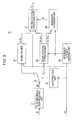
- FIG. 2 is a block diagram showing the configuration of the entropy encoder 15.
- the entropy encoder 15 includes a plus-and-minus-sign removing unit 21 for converting the predicted residual signal r[i] into a signal y[i] with no plus and minus signs, an LSB extraction unit 22 for extracting the LSB (Least Significant Bit) of m, a switch 23 for switching the output destination of the signal y[i] with no plus and minus signs in accordance with the LSB of m, a signal dividing unit 24 for performing shift computation of the signal y[i] with no plus and minus signs on the basis of the bit position m/2 and for dividing the signal y[i] into high-order bits and low-order bits, a signal dividing-operation unit 25 for performing a dividing operation on the signal y[i] with no plus and minus signs using an integer I close to 2 m/2 , a reference integer deriving unit 26 for deriving an integer I close to 2 m/2 , a variable-to-fixed length encoder 27 for converting a quot
- the plus-and-minus-sign removing unit 21 converts the predicted residual signal r[i] into a signal y[i] with no plus and minus signs on the basis of expressions (3).
- ⁇ y i 2 ⁇ r i r i ⁇ 0
- y i - 2 ⁇ r i - 1 r i ⁇ 0
- the LSB extraction unit 22 checks the least significant bit (LSB) as to whether the value of m is an even number or an odd number and extracts it. When m is 0, it is handled as an even number (hereinafter the same applies). When m is an even number, the switch 23 is switched so that the output destination of the signal y[i] with no plus and minus signs becomes the signal dividing unit 24. Furthermore, when m is an odd number, the switch 23 is switched so that the output destination of the signal y[i] with no plus and minus signs becomes the signal dividing-operation unit 25.
- LSB least significant bit
- division of a signal is performed such that the signal y[i] with no plus and minus signs is shifted by m' bits to the right to determine a quotient p i , and low-order m' bits are extracted to obtain a remainder q i .
- the quotient p i and the remainder q i obtained by the signal dividing unit 24 are output to the variable-to-fixed length encoder 27.
- variable-to-fixed length encoder 27 performs variable-length-encoding of the quotient p i , and performs fixed-length-encoding of the remainder q i using m' bits so as to convert them into a codeword I ⁇ .
- the quotient p i and the remainder q i are determined with regard to each signal y[0...N-1] with no plus and minus signs in order to convert them into a codeword I ⁇ .
- the integer I may be a value close to m squared of ⁇ 2.
- an integer I In the upper part and the lower part of expressions (6), the same integer I is used, but this is not necessarily necessary to be the same.
- the quotients p 2i and p 2i+1 determined in expressions (6) are output to the variable-to-fixed length encoder 27, and the remainders q 2i and q 2i+1 are output to the remainder combining unit 28.
- the quotients p 2i and p 2i+1 output to the variable-to-fixed length encoder 27 are variable-length-encoded in the same manner as when m is an even number.
- the remainder combining unit 28 combines the two values of the remainders q 2i and q 2i+1 so as to be converted into a combined remainder Q i .
- the remainders q 2i and q 2i+1 do not exceed the integer I. 0 ⁇ q 2 ⁇ i , q 2 ⁇ i + 1 ⁇ I
- variable-to-fixed length encoder 27 performs variable-length-encoding of the quotients p 2i and p 2i+1 , performs fixed-length-encoding of the combined remainder Q i by using m bits, and generates and outputs a codeword I ⁇ .
- the two values of the remainders q 2i and q 2i+1 are combined and converted into a combined remainder Q i
- the quotients p 2i and p 2i+1 and the combined remainder Q i are converted into a codeword I ⁇ .
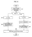
- step S31 the plus-and-minus-sign removing unit 21 converts the predicted residual signal r[i] into a signal y[i] with no plus and minus signs on the basis of expression (3) above.
- step 32 the LSB extraction unit 22 determines whether or not the value of m is an even number or an odd number on the basis of the least significant bit (LSB).
- m is an even number, that is, m is 0, the process proceeds to step S33, where the LSB extraction unit 22 switches the switch 23 so that the output destination of the signal y[i] with no plus and minus signs becomes the signal dividing unit 24.
- step S35 the LSB extraction unit 22 switches the switch 23 so that the output destination of the signal y[i] with no plus and minus signs becomes the signal dividing-operation unit 25.
- the quotient p i and the remainder q i are output to the variable-to-fixed length encoder 27.
- step S38 the variable-to-fixed length encoder 27 performs variable-length-encoding of the quotient p i , performs fixed-length-encoding of the remainder q i using m' bits, and converts them into a codeword I ⁇ .
- step S35 the reference integer deriving unit 26 derives an integer I that does not exceed m squared of ⁇ 2 in the right side of expression (2).
- step S37 the remainder combining unit 28 combines the two values of the remainders q 2i and q 2i+1 and converts them into a combined remainder Q i .
- step S38 the variable-to-fixed length encoder 27 performs variable-length-encoding of the quotients p 2i and p 2i+1 , performs fixed-length-encoding of the combined remainder Q i by using m bits, and generates and outputs a codeword I ⁇ .
- the values I' and E corresponding to expression (9) are formed as integers in the form of a table, it is possible to determine the values without performing a dividing operation or calculation of a remainder. In general, when division becomes necessary, the number of computations is increased. In the manner described above, by prestoring an integer corresponding to the reciprocal of the integer I, multiplication can be used, making it possible to decrease the number of computations.
- 2i and 2i+1 are set to i.
- the integer I is added to the remainder q i .
- the remainder q i is greater than or equal to the integer I, with respect to the addition of 1 to the quotient p i , the integer I is subtracted from the remainder q i .
- the remainders q 2i and q 2i+1 can be set to be greater than or equal to 0 and less than the integer I, thereby improving encoding efficiency.
- the signal y[i] with no plus and minus signs may be divided in advance into a low-order (m - M)/2 bit t i and a high-order bit y'[i] higher than that.
- t i y i & 2 m - M / 2 - 1
- y ⁇ i y i > > m - M / 2
- FIG. 4 is a block diagram showing the configuration of a decoder.
- a decoder 40 includes a demultiplexer 41 for demultiplexing multiplexed data so as to be decoded to a codeword I ⁇ , a reference bit position m/2, and a codeword I ⁇ , an entropy decoder 42 for converting the codeword I ⁇ into a predicted residual signal r[i] on the basis of the reference bit position m/2, a short-term prediction coefficient decoder 43 for converting the codeword I ⁇ into a short-term prediction coefficient ⁇ p , an adder 44 for computing an audio signal x[i] from a past audio signal in which correlations between the predicted residual signal r[i] and samples are combined, and a short-term combining unit 45 for generating an audio signal in which correlations between proximity samples are combined on the basis of the short-term prediction coefficient ⁇ p .
- the multiplexed data input to the demultiplexer 41 is demultiplexed so as to be decoded to individual codewords.
- the codeword I ⁇ and the bit position m/2 decoded by the demultiplexer 41 are input to the entropy decoder 42 for decoding the decoding residual signal r[i].
- the codeword I ⁇ of the short-term prediction coefficient is decoded by the short-term prediction coefficient decoder 43, generating a short-term prediction coefficient ⁇ p , and this is sent to the short-term combining unit 45.
- an audio signal x[i] is generated on the basis of the short-term prediction coefficient ⁇ p and the past decoded signal in accordance with expression (13).
- Fig. 5 is a block diagram showing the configuration of the entropy decoder 42.
- the entropy decoder 42 includes a variable-to-fixed length decoder 51 for determining whether m is an even number or an odd number and for converting a codeword I ⁇ into a quotient p i and a remainder q i or into quotients p 2i and p 2i+1 and a combined remainder Q i , a signal combining unit 52 for combining high-order bits and low-order bits on the basis of m with respect to the quotient p i and the remainder q i in order to generate a signal y[i] with no plus and minus signs, a reference integer deriving unit 53 for deriving an integer I close to m squared of ⁇ 2, a remainder dividing unit 54 for decoding the remainders q 2i and q 2i+1 from the combined remainder Q i , a signal multiplier 55 for decoding signals y[2i] and y[2i+1] with no plus and minus signs from the quotients p 2i and
- the variable-to-fixed-length decoder 51 converts the input codeword I ⁇ into a quotient p i and a remainder q i . Since m' is an integer, the signal combining unit 52 performs a shift operation for each sample in order to decode a signal y[i] with no plus and minus signs.
- y ⁇ i p ⁇ i ⁇ ⁇ m ⁇ ⁇ ⁇ ⁇
- the remainder dividing unit 54 decodes the remainders q 2i and q 2i+1 from the combined remainder Q i by using expressions (16) below.
- LSB least significant bit
- the plus-and-minus-sign restoration unit 58 converts the signal y[i] with no plus and minus signs into a decoded residual signal r[i] on the basis of expressions (18).
- ⁇ r ⁇ i y ⁇ i > > 1
- r ⁇ i ⁇ y ⁇ i > > 1
- step S61 the variable-to-fixed-length decoder 51 decodes the codeword I ⁇ and determines whether or not m is an even number or an odd number (step S62).
- step S65 the reference integer deriving unit 53 derives an integer I close to m squared of ⁇ 2.
- step S66 the remainder dividing unit 54 decodes the remainders q 2i and q 2i+1 from the combined remainder Q i on the basis of expressions (16) by using the integer I.
- step S68 the plus-and-minus-sign restoration unit 58 converts the signal y[i] with no plus and minus signs into a decoded residual signal r[i] on the basis of expressions (18).
- the remainders q 2i and q 2i+1 , and the integer I making it possible to perform decoding in which the bit position is set in 1/2 units.
- division is used.
- multiplication can also be used by forming in advance as a table a value I' corresponding to the reciprocal of the integer I as in expression (19).
- I ⁇ ⁇ ⁇ ⁇ 2 E ⁇ / I ⁇ ⁇
- t i is decoded from the codeword obtained from the demultiplexer 41.
- the combined remainder Q i is determined from the remainder q n ⁇ i+k .
- a remainder q n ⁇ i+k is determined from the combined remainder Q i in accordance with the following expression.
- the signal is subdivided. Therefore, it is possible to allocate an appropriate number of bits into the high-order bits or the low-order bits with respect to the distribution of the signal, thereby making it possible to improve encoding efficiency.
- the present invention is not limited to only the above-described embodiments. Of course, various changes are possible within the spirit and scope of the present invention.
- the present invention has been described as the configuration of hardware, but is not limited to this. Any desired processing can be realized by causing a central processing unit (CPU) to execute a computer program.
- the computer program can be provided in such a manner as to be recorded on a recording medium and also, can be provided by being transmitted via a transmission medium, such as the Internet.
- the codeword I ⁇ for these two samples becomes as, for example, the following on the basis of Table 1, and is represented using a total of 12 bits in which r[2i] is 7 bits and r[2i+1] is 5 bits.
- I Y 0 ⁇ b ⁇ 001 , 0 ⁇ b ⁇ 0101 , 0 ⁇ b ⁇ 1 , 0 ⁇ b ⁇ 1110
- the codeword I ⁇ for these two samples becomes as, for example, the following on the basis of Table 1, and r[2i] and r[2i+1] are represented using a total of 12 bits.
- I Y 0 ⁇ b ⁇ 01 , 0 ⁇ b ⁇ 1 , 0 ⁇ b ⁇ 101000011
- I is determined on the basis of expression (5).
- the signal is divided into the high-order bits and the low-order bits on the basis of expression (12) above.
- Remainders q 2i and q 2i+1 are determined from the combined remainder Q i on the basis of expressions (16).
- the present invention can be applied to lossless compression technology for a 44 kHz, 16-bit or 96 kHz 24-bit stereo sound source.
- compression efficiency in a case of the related art in which Golomb-Rice encoding is applied and in a case in which the present invention is applied were verified.
- ratio original_file_size - compressed_file_size original_file_size ⁇ 100 %
- original_file_size is the file size of the original sound
- compressed_file_size is the size of a compressed file. It is shown that the higher the ratio, the higher the compression efficiency.
- Table 2 Comparison of Compression Efficiency Between Proposed Method and Method of Related Art Sound Source File Performance Time Period [Seconds] Ratio Proposed Method [%] Method of Related Art [%] Difference [%] Sound Source 1 10 61.893 61.821 0.072 Sound Source 2 20 42.594 42.472 0.122 Sound Source 3 20 47.202 47.080 0.122 Sound Source 4 20 43.887 43.771 0.116 Sound Source 5 20 37.455 37.310 0.145 Sound Source 6 20 62.047 62.008 0.309 Sound Source 7 30 40.847 40.723 0.124 Total 140 47.523 47.419 0.104
- the compression efficiency can be improved by 0.1% or more.
- Table 3 shows a frequency distribution determined with regard to a quotient p i for 2048 samples on which variable-length encoding is performed. It is assumed here that, similarly to Golomb-Rice encoding, the bit length of the codeword of the quotient p i is p i + 1 bits.
Landscapes
- Engineering & Computer Science (AREA)
- Theoretical Computer Science (AREA)
- Compression, Expansion, Code Conversion, And Decoders (AREA)
- Compression Or Coding Systems Of Tv Signals (AREA)
Applications Claiming Priority (1)
| Application Number | Priority Date | Filing Date | Title |
|---|---|---|---|
| JP2007277930A JP4888335B2 (ja) | 2007-10-25 | 2007-10-25 | 符号化方法及び装置、並びにプログラム |
Publications (3)
| Publication Number | Publication Date |
|---|---|
| EP2053749A2 true EP2053749A2 (de) | 2009-04-29 |
| EP2053749A3 EP2053749A3 (de) | 2009-07-29 |
| EP2053749B1 EP2053749B1 (de) | 2015-01-21 |
Family
ID=40404091
Family Applications (1)
| Application Number | Title | Priority Date | Filing Date |
|---|---|---|---|
| EP20080253456 Not-in-force EP2053749B1 (de) | 2007-10-25 | 2008-10-24 | Kodierungsverfahren, Vorrichtung und Programm |
Country Status (4)
| Country | Link |
|---|---|
| US (1) | US7791510B2 (de) |
| EP (1) | EP2053749B1 (de) |
| JP (1) | JP4888335B2 (de) |
| CN (1) | CN101420231A (de) |
Cited By (1)
| Publication number | Priority date | Publication date | Assignee | Title |
|---|---|---|---|---|
| WO2011162723A1 (en) * | 2010-06-21 | 2011-12-29 | Agency For Science, Technology And Research | Entropy encoder arrangement and entropy decoder arrangement |
Families Citing this family (14)
| Publication number | Priority date | Publication date | Assignee | Title |
|---|---|---|---|---|
| US8502708B2 (en) * | 2008-12-09 | 2013-08-06 | Nippon Telegraph And Telephone Corporation | Encoding method and decoding method, and devices, program and recording medium for the same |
| CN101609680B (zh) * | 2009-06-01 | 2012-01-04 | 华为技术有限公司 | 压缩编码和解码的方法、编码器和解码器以及编码装置 |
| JP5413007B2 (ja) * | 2009-07-15 | 2014-02-12 | 株式会社ニコン | 画像圧縮装置、撮像装置、プログラムおよび画像伸張装置 |
| JP5524584B2 (ja) * | 2009-11-20 | 2014-06-18 | キヤノン株式会社 | 画像処理装置及びその制御方法 |
| CN101980464B (zh) * | 2010-09-30 | 2013-01-16 | 华为技术有限公司 | 数据编码方法、解码方法、编码器和解码器 |
| CN103262531B (zh) * | 2010-12-14 | 2017-03-15 | 瑞典爱立信有限公司 | 用于在图块编码中在像素值缓冲器中存储压缩比率指示的方法和设备 |
| WO2013058634A2 (ko) | 2011-10-21 | 2013-04-25 | 삼성전자 주식회사 | 에너지 무손실 부호화방법 및 장치, 오디오 부호화방법 및 장치, 에너지 무손실 복호화방법 및 장치, 및 오디오 복호화방법 및 장치 |
| JP6052815B2 (ja) | 2014-09-30 | 2016-12-27 | インターナショナル・ビジネス・マシーンズ・コーポレーションInternational Business Machines Corporation | 導波路用のコネクタおよびアライメント方法 |
| CN104486067B (zh) * | 2014-12-02 | 2017-12-19 | 浪潮(北京)电子信息产业有限公司 | 一种生成固定长度序列号的方法及装置 |
| EP3241351B1 (de) * | 2015-01-30 | 2021-04-28 | MediaTek Inc. | Verfahren zur entropiecodierung von quellenabtastwerten mit grossem alphabet |
| US9979415B2 (en) | 2015-02-16 | 2018-05-22 | Mitsubishi Electric Corporation | Data compression apparatus, data decompression apparatus, data compression method, data compression method, and computer readable medium |
| TWI681396B (zh) * | 2018-12-06 | 2020-01-01 | 群聯電子股份有限公司 | 解碼方法、記憶體控制電路單元以及記憶體儲存裝置 |
| CN109600618B (zh) * | 2018-12-19 | 2021-12-24 | 上海数迹智能科技有限公司 | 视频压缩方法、解压缩方法、装置、终端和介质 |
| JP2023184342A (ja) | 2022-06-17 | 2023-12-28 | キオクシア株式会社 | エンコーダ及びデコーダ |
Citations (2)
| Publication number | Priority date | Publication date | Assignee | Title |
|---|---|---|---|---|
| JP2006140772A (ja) | 2004-11-12 | 2006-06-01 | Sony Corp | 符号化装置とその符号化方法およびプログラム |
| JP2007277930A (ja) | 2006-04-06 | 2007-10-25 | Hitachi Constr Mach Co Ltd | 建設機械の作業装置 |
Family Cites Families (8)
| Publication number | Priority date | Publication date | Assignee | Title |
|---|---|---|---|---|
| JPH07111633A (ja) * | 1993-10-14 | 1995-04-25 | Matsushita Electric Ind Co Ltd | 画像圧縮記録再生装置 |
| EP1603244B1 (de) * | 1996-11-07 | 2007-08-22 | Koninklijke Philips Electronics N.V. | Übertragung eines Bitstromsignals |
| US6028541A (en) * | 1998-03-12 | 2000-02-22 | Liquid Audio Inc. | Lossless data compression with low complexity |
| JP3796354B2 (ja) * | 1998-05-29 | 2006-07-12 | 秀夫 北島 | 画像符号化方法 |
| EP1368898A2 (de) | 2001-03-05 | 2003-12-10 | Koninklijke Philips Electronics N.V. | Vorrichtung und verfahren zur signalkomprimierung |
| JP4357852B2 (ja) * | 2003-02-24 | 2009-11-04 | 大日本印刷株式会社 | 時系列信号の圧縮解析装置および変換装置 |
| JP2005027206A (ja) * | 2003-07-01 | 2005-01-27 | Nikon Corp | 階調変換処理装置、電子カメラおよび階調変換プログラム |
| US7580585B2 (en) | 2004-10-29 | 2009-08-25 | Microsoft Corporation | Lossless adaptive Golomb/Rice encoding and decoding of integer data using backward-adaptive rules |
-
2007
- 2007-10-25 JP JP2007277930A patent/JP4888335B2/ja not_active Expired - Fee Related
-
2008
- 2008-10-23 US US12/257,371 patent/US7791510B2/en not_active Expired - Fee Related
- 2008-10-24 EP EP20080253456 patent/EP2053749B1/de not_active Not-in-force
- 2008-10-27 CN CNA2008101691251A patent/CN101420231A/zh active Pending
Patent Citations (2)
| Publication number | Priority date | Publication date | Assignee | Title |
|---|---|---|---|---|
| JP2006140772A (ja) | 2004-11-12 | 2006-06-01 | Sony Corp | 符号化装置とその符号化方法およびプログラム |
| JP2007277930A (ja) | 2006-04-06 | 2007-10-25 | Hitachi Constr Mach Co Ltd | 建設機械の作業装置 |
Cited By (1)
| Publication number | Priority date | Publication date | Assignee | Title |
|---|---|---|---|---|
| WO2011162723A1 (en) * | 2010-06-21 | 2011-12-29 | Agency For Science, Technology And Research | Entropy encoder arrangement and entropy decoder arrangement |
Also Published As
| Publication number | Publication date |
|---|---|
| JP2009105838A (ja) | 2009-05-14 |
| US7791510B2 (en) | 2010-09-07 |
| JP4888335B2 (ja) | 2012-02-29 |
| US20090109070A1 (en) | 2009-04-30 |
| CN101420231A (zh) | 2009-04-29 |
| EP2053749B1 (de) | 2015-01-21 |
| EP2053749A3 (de) | 2009-07-29 |
Similar Documents
| Publication | Publication Date | Title |
|---|---|---|
| EP2053749B1 (de) | Kodierungsverfahren, Vorrichtung und Programm | |
| KR100975062B1 (ko) | 가변길이 부호화 장치 및 가변길이 부호화 방법 | |
| KR101737294B1 (ko) | 심볼 압축을 수반하는 데이터의 소스 코딩 및 디코딩을 위한 방법들 및 디바이스들 | |
| KR100552665B1 (ko) | 키 데이터 부호화/복호화 방법 및 장치 | |
| CN1781253B (zh) | 浮点格式的数字信号的无损编码方法、解码方法及其装置 | |
| CN100495930C (zh) | 浮点信号可逆编码方法、解码方法及其设备 | |
| EP2214315A1 (de) | Verfahren und Vorrichtung zum Kodieren einer Bitfolge | |
| KR930024507A (ko) | 영상데이타의 가변장부호화/복호화방법 및 장치 | |
| JP2017511997A (ja) | データのソース符号化及び復号の装置及びその方法 | |
| US7408481B2 (en) | Information encoding method, decoding method, common multiplier estimating method, and apparatus, program, and recording medium using these methods | |
| CN104380733B (zh) | 视频量化参数编码方法、视频量化参数解码方法、设备 | |
| RU2611249C1 (ru) | Модификатор энтропии и способ его использования | |
| KR20110043684A (ko) | 디지털 신호의 압축 또는 압축해제를 위한 방법, 시스템 및 장치 | |
| KR20250021656A (ko) | 정수값의 시퀀스를 인코딩 및 디코딩하는 장치, 정수값의 시퀀스를 인코딩 및 디코딩하는 방법 및 이러한 방법을 구현하기 위한 컴퓨터 프로그램 | |
| RU2709656C2 (ru) | Кодер, декодер и способ, использующие модовые символы | |
| US20120280838A1 (en) | Data compression device, data compression method, and program | |
| JP2008311803A (ja) | 算術復号方法、算術復号装置及び算術復号プログラム | |
| KR101549740B1 (ko) | 이진 데이터의 압축 및 압축해제 방법과 장치 | |
| US8754791B1 (en) | Entropy modifier and method | |
| KR101086430B1 (ko) | 압축 부호화된 영상 데이터 스트림의 역양자화 방법 및 그장치 | |
| KR100686354B1 (ko) | 가변 트리를 이용한 허프만 복호화 방법 및 장치 | |
| JP2560987B2 (ja) | 画像処理装置 | |
| KR101760070B1 (ko) | 데이터 부호화 및 복호화 방법과 장치 | |
| EP1750447A2 (de) | Verfahren und Vorrichtung zur Kodierung und Dekodierung von Schlüsseldaten | |
| JPH0969782A (ja) | オーディオデータ符号化装置 |
Legal Events
| Date | Code | Title | Description |
|---|---|---|---|
| PUAI | Public reference made under article 153(3) epc to a published international application that has entered the european phase |
Free format text: ORIGINAL CODE: 0009012 |
|
| 17P | Request for examination filed |
Effective date: 20081106 |
|
| AK | Designated contracting states |
Kind code of ref document: A2 Designated state(s): AT BE BG CH CY CZ DE DK EE ES FI FR GB GR HR HU IE IS IT LI LT LU LV MC MT NL NO PL PT RO SE SI SK TR |
|
| AX | Request for extension of the european patent |
Extension state: AL BA MK RS |
|
| PUAL | Search report despatched |
Free format text: ORIGINAL CODE: 0009013 |
|
| AK | Designated contracting states |
Kind code of ref document: A3 Designated state(s): AT BE BG CH CY CZ DE DK EE ES FI FR GB GR HR HU IE IS IT LI LT LU LV MC MT NL NO PL PT RO SE SI SK TR |
|
| AX | Request for extension of the european patent |
Extension state: AL BA MK RS |
|
| 17Q | First examination report despatched |
Effective date: 20091019 |
|
| AKX | Designation fees paid |
Designated state(s): DE FR GB |
|
| RIC1 | Information provided on ipc code assigned before grant |
Ipc: H03M 7/40 20060101ALI20130823BHEP Ipc: H04N 7/26 20060101AFI20130823BHEP |
|
| GRAP | Despatch of communication of intention to grant a patent |
Free format text: ORIGINAL CODE: EPIDOSNIGR1 |
|
| RIC1 | Information provided on ipc code assigned before grant |
Ipc: H03M 7/40 20060101AFI20140707BHEP |
|
| INTG | Intention to grant announced |
Effective date: 20140813 |
|
| GRAS | Grant fee paid |
Free format text: ORIGINAL CODE: EPIDOSNIGR3 |
|
| GRAA | (expected) grant |
Free format text: ORIGINAL CODE: 0009210 |
|
| AK | Designated contracting states |
Kind code of ref document: B1 Designated state(s): DE FR GB |
|
| REG | Reference to a national code |
Ref country code: GB Ref legal event code: FG4D |
|
| REG | Reference to a national code |
Ref country code: DE Ref legal event code: R096 Ref document number: 602008036435 Country of ref document: DE Effective date: 20150305 |
|
| REG | Reference to a national code |
Ref country code: DE Ref legal event code: R084 Ref document number: 602008036435 Country of ref document: DE |
|
| REG | Reference to a national code |
Ref country code: GB Ref legal event code: 746 Effective date: 20150421 |
|
| REG | Reference to a national code |
Ref country code: DE Ref legal event code: R084 Ref document number: 602008036435 Country of ref document: DE Effective date: 20150410 |
|
| REG | Reference to a national code |
Ref country code: DE Ref legal event code: R097 Ref document number: 602008036435 Country of ref document: DE |
|
| REG | Reference to a national code |
Ref country code: FR Ref legal event code: PLFP Year of fee payment: 8 |
|
| PLBE | No opposition filed within time limit |
Free format text: ORIGINAL CODE: 0009261 |
|
| STAA | Information on the status of an ep patent application or granted ep patent |
Free format text: STATUS: NO OPPOSITION FILED WITHIN TIME LIMIT |
|
| 26N | No opposition filed |
Effective date: 20151022 |
|
| REG | Reference to a national code |
Ref country code: FR Ref legal event code: PLFP Year of fee payment: 9 |
|
| REG | Reference to a national code |
Ref country code: FR Ref legal event code: PLFP Year of fee payment: 10 |
|
| REG | Reference to a national code |
Ref country code: FR Ref legal event code: PLFP Year of fee payment: 11 |
|
| PGFP | Annual fee paid to national office [announced via postgrant information from national office to epo] |
Ref country code: FR Payment date: 20191028 Year of fee payment: 12 |
|
| PGFP | Annual fee paid to national office [announced via postgrant information from national office to epo] |
Ref country code: GB Payment date: 20191021 Year of fee payment: 12 |
|
| PGFP | Annual fee paid to national office [announced via postgrant information from national office to epo] |
Ref country code: DE Payment date: 20201022 Year of fee payment: 13 |
|
| GBPC | Gb: european patent ceased through non-payment of renewal fee |
Effective date: 20201024 |
|
| PG25 | Lapsed in a contracting state [announced via postgrant information from national office to epo] |
Ref country code: FR Free format text: LAPSE BECAUSE OF NON-PAYMENT OF DUE FEES Effective date: 20201031 |
|
| PG25 | Lapsed in a contracting state [announced via postgrant information from national office to epo] |
Ref country code: GB Free format text: LAPSE BECAUSE OF NON-PAYMENT OF DUE FEES Effective date: 20201024 |
|
| REG | Reference to a national code |
Ref country code: DE Ref legal event code: R119 Ref document number: 602008036435 Country of ref document: DE |
|
| PG25 | Lapsed in a contracting state [announced via postgrant information from national office to epo] |
Ref country code: DE Free format text: LAPSE BECAUSE OF NON-PAYMENT OF DUE FEES Effective date: 20220503 |