EP2054571B1 - Dispositif et procédé permettant de raccorder détachables des parties structurelles, en particulier dans un aéronef - Google Patents
Dispositif et procédé permettant de raccorder détachables des parties structurelles, en particulier dans un aéronef Download PDFInfo
- Publication number
- EP2054571B1 EP2054571B1 EP20070786298 EP07786298A EP2054571B1 EP 2054571 B1 EP2054571 B1 EP 2054571B1 EP 20070786298 EP20070786298 EP 20070786298 EP 07786298 A EP07786298 A EP 07786298A EP 2054571 B1 EP2054571 B1 EP 2054571B1
- Authority
- EP
- European Patent Office
- Prior art keywords
- clamping lever
- eccentric shaft
- section
- clamping
- eccentric
- Prior art date
- Legal status (The legal status is an assumption and is not a legal conclusion. Google has not performed a legal analysis and makes no representation as to the accuracy of the status listed.)
- Not-in-force
Links
- 238000000034 method Methods 0.000 title claims abstract description 9
- 230000033001 locomotion Effects 0.000 claims description 18
- 210000000078 claw Anatomy 0.000 claims description 14
- 230000005489 elastic deformation Effects 0.000 claims description 5
- 230000008878 coupling Effects 0.000 claims description 4
- 238000010168 coupling process Methods 0.000 claims description 4
- 238000005859 coupling reaction Methods 0.000 claims description 4
- 230000000903 blocking effect Effects 0.000 claims description 3
- 238000006073 displacement reaction Methods 0.000 description 3
- 230000007246 mechanism Effects 0.000 description 3
- 230000004048 modification Effects 0.000 description 3
- 238000012986 modification Methods 0.000 description 3
- 238000004519 manufacturing process Methods 0.000 description 2
- 230000007704 transition Effects 0.000 description 2
- 230000009471 action Effects 0.000 description 1
- 230000010006 flight Effects 0.000 description 1
- 230000000717 retained effect Effects 0.000 description 1
- 238000007493 shaping process Methods 0.000 description 1
- 230000009466 transformation Effects 0.000 description 1
Images

Classifications
-
- F—MECHANICAL ENGINEERING; LIGHTING; HEATING; WEAPONS; BLASTING
- F16—ENGINEERING ELEMENTS AND UNITS; GENERAL MEASURES FOR PRODUCING AND MAINTAINING EFFECTIVE FUNCTIONING OF MACHINES OR INSTALLATIONS; THERMAL INSULATION IN GENERAL
- F16B—DEVICES FOR FASTENING OR SECURING CONSTRUCTIONAL ELEMENTS OR MACHINE PARTS TOGETHER, e.g. NAILS, BOLTS, CIRCLIPS, CLAMPS, CLIPS OR WEDGES; JOINTS OR JOINTING
- F16B5/00—Joining sheets or plates, e.g. panels, to one another or to strips or bars parallel to them
- F16B5/0004—Joining sheets, plates or panels in abutting relationship
- F16B5/0084—Joining sheets, plates or panels in abutting relationship characterised by particular locking means
-
- E—FIXED CONSTRUCTIONS
- E05—LOCKS; KEYS; WINDOW OR DOOR FITTINGS; SAFES
- E05B—LOCKS; ACCESSORIES THEREFOR; HANDCUFFS
- E05B17/00—Accessories in connection with locks
- E05B17/0025—Devices for forcing the wing firmly against its seat or to initiate the opening of the wing
-
- E—FIXED CONSTRUCTIONS
- E05—LOCKS; KEYS; WINDOW OR DOOR FITTINGS; SAFES
- E05B—LOCKS; ACCESSORIES THEREFOR; HANDCUFFS
- E05B65/00—Locks or fastenings for special use
- E05B65/08—Locks or fastenings for special use for sliding wings
- E05B65/0811—Locks or fastenings for special use for sliding wings the bolts pivoting about an axis perpendicular to the wings
- E05B65/0817—Locks or fastenings for special use for sliding wings the bolts pivoting about an axis perpendicular to the wings with additional movement, e.g. toggle, overcenter, excentric
-
- E—FIXED CONSTRUCTIONS
- E05—LOCKS; KEYS; WINDOW OR DOOR FITTINGS; SAFES
- E05C—BOLTS OR FASTENING DEVICES FOR WINGS, SPECIALLY FOR DOORS OR WINDOWS
- E05C3/00—Fastening devices with bolts moving pivotally or rotatively
- E05C3/02—Fastening devices with bolts moving pivotally or rotatively without latching action
- E05C3/04—Fastening devices with bolts moving pivotally or rotatively without latching action with operating handle or equivalent member rigid with the bolt
- E05C3/041—Fastening devices with bolts moving pivotally or rotatively without latching action with operating handle or equivalent member rigid with the bolt rotating about an axis perpendicular to the surface on which the fastener is mounted
- E05C3/045—Fastening devices with bolts moving pivotally or rotatively without latching action with operating handle or equivalent member rigid with the bolt rotating about an axis perpendicular to the surface on which the fastener is mounted in the form of a hook
-
- F—MECHANICAL ENGINEERING; LIGHTING; HEATING; WEAPONS; BLASTING
- F16—ENGINEERING ELEMENTS AND UNITS; GENERAL MEASURES FOR PRODUCING AND MAINTAINING EFFECTIVE FUNCTIONING OF MACHINES OR INSTALLATIONS; THERMAL INSULATION IN GENERAL
- F16B—DEVICES FOR FASTENING OR SECURING CONSTRUCTIONAL ELEMENTS OR MACHINE PARTS TOGETHER, e.g. NAILS, BOLTS, CIRCLIPS, CLAMPS, CLIPS OR WEDGES; JOINTS OR JOINTING
- F16B2/00—Friction-grip releasable fastenings
- F16B2/02—Clamps, i.e. with gripping action effected by positive means other than the inherent resistance to deformation of the material of the fastening
- F16B2/18—Clamps, i.e. with gripping action effected by positive means other than the inherent resistance to deformation of the material of the fastening using cams, levers, eccentrics, or toggles
- F16B2/185—Clamps, i.e. with gripping action effected by positive means other than the inherent resistance to deformation of the material of the fastening using cams, levers, eccentrics, or toggles using levers
-
- E—FIXED CONSTRUCTIONS
- E05—LOCKS; KEYS; WINDOW OR DOOR FITTINGS; SAFES
- E05B—LOCKS; ACCESSORIES THEREFOR; HANDCUFFS
- E05B65/00—Locks or fastenings for special use
- E05B65/006—Locks or fastenings for special use for covers or panels
-
- Y—GENERAL TAGGING OF NEW TECHNOLOGICAL DEVELOPMENTS; GENERAL TAGGING OF CROSS-SECTIONAL TECHNOLOGIES SPANNING OVER SEVERAL SECTIONS OF THE IPC; TECHNICAL SUBJECTS COVERED BY FORMER USPC CROSS-REFERENCE ART COLLECTIONS [XRACs] AND DIGESTS
- Y10—TECHNICAL SUBJECTS COVERED BY FORMER USPC
- Y10S—TECHNICAL SUBJECTS COVERED BY FORMER USPC CROSS-REFERENCE ART COLLECTIONS [XRACs] AND DIGESTS
- Y10S292/00—Closure fasteners
- Y10S292/55—Bolt and keeper aligners
-
- Y—GENERAL TAGGING OF NEW TECHNOLOGICAL DEVELOPMENTS; GENERAL TAGGING OF CROSS-SECTIONAL TECHNOLOGIES SPANNING OVER SEVERAL SECTIONS OF THE IPC; TECHNICAL SUBJECTS COVERED BY FORMER USPC CROSS-REFERENCE ART COLLECTIONS [XRACs] AND DIGESTS
- Y10—TECHNICAL SUBJECTS COVERED BY FORMER USPC
- Y10T—TECHNICAL SUBJECTS COVERED BY FORMER US CLASSIFICATION
- Y10T292/00—Closure fasteners
- Y10T292/08—Bolts
- Y10T292/0863—Sliding and rotary
-
- Y—GENERAL TAGGING OF NEW TECHNOLOGICAL DEVELOPMENTS; GENERAL TAGGING OF CROSS-SECTIONAL TECHNOLOGIES SPANNING OVER SEVERAL SECTIONS OF THE IPC; TECHNICAL SUBJECTS COVERED BY FORMER USPC CROSS-REFERENCE ART COLLECTIONS [XRACs] AND DIGESTS
- Y10—TECHNICAL SUBJECTS COVERED BY FORMER USPC
- Y10T—TECHNICAL SUBJECTS COVERED BY FORMER US CLASSIFICATION
- Y10T292/00—Closure fasteners
- Y10T292/08—Bolts
- Y10T292/0886—Sliding and swinging
-
- Y—GENERAL TAGGING OF NEW TECHNOLOGICAL DEVELOPMENTS; GENERAL TAGGING OF CROSS-SECTIONAL TECHNOLOGIES SPANNING OVER SEVERAL SECTIONS OF THE IPC; TECHNICAL SUBJECTS COVERED BY FORMER USPC CROSS-REFERENCE ART COLLECTIONS [XRACs] AND DIGESTS
- Y10—TECHNICAL SUBJECTS COVERED BY FORMER USPC
- Y10T—TECHNICAL SUBJECTS COVERED BY FORMER US CLASSIFICATION
- Y10T292/00—Closure fasteners
- Y10T292/08—Bolts
- Y10T292/1039—Swinging and camming
-
- Y—GENERAL TAGGING OF NEW TECHNOLOGICAL DEVELOPMENTS; GENERAL TAGGING OF CROSS-SECTIONAL TECHNOLOGIES SPANNING OVER SEVERAL SECTIONS OF THE IPC; TECHNICAL SUBJECTS COVERED BY FORMER USPC CROSS-REFERENCE ART COLLECTIONS [XRACs] AND DIGESTS
- Y10—TECHNICAL SUBJECTS COVERED BY FORMER USPC
- Y10T—TECHNICAL SUBJECTS COVERED BY FORMER US CLASSIFICATION
- Y10T292/00—Closure fasteners
- Y10T292/08—Bolts
- Y10T292/1043—Swinging
-
- Y—GENERAL TAGGING OF NEW TECHNOLOGICAL DEVELOPMENTS; GENERAL TAGGING OF CROSS-SECTIONAL TECHNOLOGIES SPANNING OVER SEVERAL SECTIONS OF THE IPC; TECHNICAL SUBJECTS COVERED BY FORMER USPC CROSS-REFERENCE ART COLLECTIONS [XRACs] AND DIGESTS
- Y10—TECHNICAL SUBJECTS COVERED BY FORMER USPC
- Y10T—TECHNICAL SUBJECTS COVERED BY FORMER US CLASSIFICATION
- Y10T70/00—Locks
- Y10T70/50—Special application
- Y10T70/5093—For closures
- Y10T70/5155—Door
- Y10T70/5164—Links to limit opening
Definitions
- the present invention relates to a device and a method for the detachable connection of structural parts, in particular in an aircraft.
- modem aircraft it is often necessary to install and dismantle individual structural elements quickly.
- certain facilities are designated that can easily be removed from a stowed or inoperative state, so that they can be used temporarily.
- An example of such are rest stations for the flight crew, also termed flight crew rest compartments.
- rest stations should be able to be removed easily from their stowed position, so that areas lying behind them are easily accessible for use by the flight crew.
- these rest stations have to be brought once more in a space-saving and above all mechanically safe manner into their stowed position, in which they are safely retained and occupy as little space as possible.
- connection mechanisms were as a rule relatively simple to operate, they suffered from a large number of disadvantages.
- bar-type solutions cannot withstand the constant vibrations and cannot guarantee a reliable permanent connection of the structural elements.
- Connection mechanisms involving loose parts moreover conceal the danger that the parts could be lost, with the result that the connection mechanism is no longer usable.
- the object of the present invention is accordingly to provide a device and a method for the detachable connection of structural parts in an aircraft, which by dispensing with loose parts guarantees a secure and permanent connection and is characterised by a high ergonomic efficiency.
- the device according to the invention includes a clamping lever, which can be swivellably displaced by the driving bushing and the eccentric shaft.
- the clamping lever can be brought from the release position, in which the two structural parts to be joined can be detached from one another, via the readiness position, in which the two structural parts to be joined are positioned relative to one another, into the locking position, in which the two structural parts to be joined are firmly locked to one another.
- the locking preferably takes place by creating a state of tension, so that the two structural parts to be joined to one another are braced against one another and are thereby securely held on one another also in the event of vibrations.
- the tension forces occurring in this connection are generated by changing the clamping lever arrangement from the readiness position to the locking position, and are chosen so as to counteract any unintended loosening due to vibrations that occur.
- the interlocking positive engagement of the clamping lever on the clamping pin increases the operational reliability of the device according to the invention and reduces still further the risk of an unintended loosening of the device according to the invention.
- the driving bushing is swivellably mounted on the eccentric shaft.
- the clamping lever is eccentrically swivellably mounted relative to the rotation axis on an eccentric section of the eccentric shaft.
- the clamping lever comprises a bearing section receiving the eccentric shaft, and a claw or driver section that can be brought into interlocking engagement with the clamping pin. According to the invention the clamping lever can thus be displaced by rotating the eccentric shaft.
- the clamping lever swivels about a pivot axis defined by the eccentric section, which differs however from the rotation axis of the eccentric shaft.
- a preferred embodiment of the invention envisages that the bearing section has a stop means which, together with a counter-stop provided on the first structural part, defines the release position of the clamping lever arrangement.
- the provision of a stop means as well as a counter-stop provides an unambiguous definition of the release position of the clamping lever arrangement.
- the clamping lever arrangement can be tensioned in a spring-like manner in the direction of this release position.
- a preferred embodiment of the invention envisages that this comprises a bearing surface, which in the readiness position rests on the clamping pin before reaching the locking position.
- the readiness position is thereby also predefined.
- the bearing surface of the claw section and further functional surfaces of the claw section which will subsequently produce an interlocking positive connection of the clamping lever and clamping pin, are according to the invention configured in such a way that tightening bevelled sections are formed, which bring the clamping lever and the clamping pin into defined relative positions with respect to one another when the clamping lever arrangement moves from the readiness position to the locking position.
- a preferred embodiment of the invention envisages that the bearing section and the claw section are connected to one another via an elastically spring-acting connecting arm.
- the connecting arm is in this variant elastically deformed during the transformation from the readiness position to the locking position, and thus clamps together the two structural parts to be locked.
- the elastically spring-acting connecting arm can on the one hand be formed of an elastically deformable material.
- a suitably spring-acting behaviour can additionally or alternatively be achieved by shaping, for example in the manner of a curved clamping hoop.
- the claw section engages on the clamping pin and, under elastic deformation of the connecting arm, clamps the first structural part to the second structural part.
- the clamping lever comprises a drive groove provided in the bearing section.
- the driving bushing comprises a drive lug which engages in the drive groove for the geared coupling of the driving bushing with the clamping lever.
- the driving bushing, which is swivellably mounted on the eccentric shaft, and the clamping lever, which is likewise swivellably mounted on the eccentric shaft rotate about different rotation axes during a relative rotation relative to the eccentric shaft.
- the drive lug has rounded side slopes.
- the rounded side slopes of the drive lug slide in a low-friction manner on the side slopes of the drive groove in the case of a translational movement of the drive lug and drive groove caused by the eccentricity described above.
- the drive lug comprises a stop surface situated radially inwardly with respect to the rotation axis, which in the locking position engages in a blocking manner with the eccentric section.
- the stop surface is configured in such a way that in the movement of the clamping lever arrangement from the readiness position to the locking position the eccentric section of the eccentric shaft can move beyond an eccentric dead point about a locking angle relative to the driving bushing, before the stop surface abuts the eccentric sections.
- engagement profiled sections in particular hexagonal profiled sections, may be provided in all cases on the latter.
- an external hexagonal profiled section can be arranged on the driving bushing, and a corresponding internal hexagonal profile section can be arranged on the eccentric shaft.
- the invention furthermore relates to a method for the detachable connection of structural parts in an aircraft according to claim 13.
- the aforedescribed process steps are executed in the reverse order so as to detach the structural parts from one another by moving the clamping lever arrangement from its locking position via its readiness position to its release position.
- a preferred embodiment of the invention envisages that the swivelling of the driving bushing and the swivelling of the eccentric shaft when connecting as well as when detaching the structural parts take place in each case in the same direction of rotation.
- a device according to the invention for connecting two structural parts for example two structural elements in an aircraft, are shown separately and are generally identified by the reference numeral 10.
- the structure of the device according to the invention is described hereinafter with reference to Figs. 1 to 5 .
- the device 10 according to the invention includes a clamping lever arrangement 12, which is arranged on one of the structural parts to be connected, as well as a clamping pin 14, which is arranged on the other structural part.
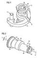
- the clamping lever arrangement 12 includes a clamping lever 16, a driving bushing 18 and an eccentric shaft 20, which are mounted in the manner shown in Fig. 1 .
- the eccentric shaft 20 is shown in a perspective view as a single part in Fig. 2 .
- this first structural part to be connected comprises a corresponding receiving opening, which is also described hereinafter with reference to Fig. 13 .
- a shank section 26 adjoins the bearing section 24.
- An eccentric section 28 adjoins the shank section 26 in the direction of the longitudinal axis A.
- a bearing shank 30 of smaller diameter compared to the shank section 26 extends in the axial direction.
- This bearing shank has at its right-hand end in Fig. 2 a circumferential recess 32 for receiving a locking ring.
- the bearing shank 30 is provided on its right-hand front surface 36 in Fig. 2 with an internal hexagonal opening 34, which can receive a corresponding external hexagonal tool.
- the eccentric shaft 20 has on its front surface 36 a notch marking 38, the purpose of which will be discussed in more detail hereinafter.
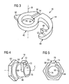
- Fig. 3 shows the clamping lever 16 in a perspective individual representation.
- the clamping lever 16 comprises a bearing section 40, which surrounds a circular cylindrical bearing opening 42.
- the internal diameter of the circular cylindrical bearing opening 42 matches the external diameter of the eccentric section 28 of the eccentric shaft 20, so that the clamping lever 16 can accommodate the eccentric section 28 free from play but in a rotationally movable manner in its bearing opening 42.
- An arch-shaped connecting arm 44 adjoins the bearing section 40, the arm running tangentially from the bearing section 40 and tapering towards its free end.
- a claw section 46 into which the connecting arm 44 transforms smoothly, is formed at the end of the connecting arm 44.
- This claw section has a stop tooth 48, which is provided with a bearing surface 50.
- a receiving cavity 52 which as shown in Fig. 1 can surround the clamping pin 14 in an interlocking positive manner, progresses in a steady transition from the bearing surface 50.
- clamping lever 16 comprises a driving groove 54, which is bounded by lateral slopes 56 and 58.
- a stop lug 60 is formed on the bearing section 40, which lug - as will be discussed in more detail hereinafter - is effective in defining the release position.
- Fig. 3 there can also be seen the swivelling axis B of the swivelling lever 16, which in the mounted state coincides with the eccentric axis E of the eccentric shaft, as shown in Fig. 2 .
- the driving bushing 18 is illustrated in Figs. 4 and 5, Fig. 4 showing a perspective representation and Fig. 5 a side view from the left.
- the driving bushing 18 is, as shown in Fig. 4 , formed at its left-hand end in the figure first of all with an outer hexagonal profiled section 62.
- This is adjoined by a bearing section 64, which serves for the bearing in a corresponding recess in the first structural part, and has roughly the same diameter as the bearing section 24 on the eccentric shaft 20.
- the bearing section 64 is adjoined by a shank section 66 of smaller diameter, on the free end of which is formed a bracket 68.
- the bracket 68 has conically running side surfaces and is provided on its free end with a drive lug 70, which projects in the direction of the longitudinal axis C.
- the drive lug 70 has rounded side slopes 72 and 74.
- the drive lug has on its radially internally lying region a similarly rounded and asymmetrically running stop surface 76.
- the round contour of the stop surface 76 corresponds roughly to the round contour of the jacket surface of the eccentric section 28 of the eccentric shaft 20.
- the driving bushing 18 is provided with a through hole 78, the internal diameter of which matches the external diameter of the bearing shank 30 of the eccentric shaft.
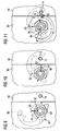
- Figs. 12 and 13 With regard to the mounting of the lever arrangement according to the invention on a first structural part 80, reference is made to Figs. 12 and 13 . It can be seen that the clamping lever 16 is mounted on the eccentric section 28 of the eccentric shaft 20. The clamping lever is prevented, in a manner not shown, from sliding underneath the eccentric section.
- the eccentric shaft 20 is inserted into the first structural part 80 and lies, with its bearing section 24, in a corresponding opening of the first structural part 80.
- the eccentric shaft 20 lies with its flange 22 on the outside of the first structural part 80.
- the driving bushing 18 is mounted on the end of the eccentric shaft 20 remote from the flange and is held in place by means of a locking ring 82.
- the clamping pin 14 is fixed in a second structural part 84, in which connection the second structural part 84 is to be detachably connected to the first structural part 80.
- connection the two structural parts to be connected to one another can be aligned relative to one another by means of dowel pins.
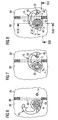
- Fig. 6 shows the release position.
- the clamping lever 16 is shown in the "swung-in" position. This means that the clamping lever 16 lies in the first structural part 80 and also does not project from an opening 86 of a side wall 88 of the first structural part.
- the position of the clamping lever 16 in the release position according to Fig. 6 is defined by the fact that the stop lug 16 abuts from the inside against the side wall 88, so that the clamping lever 16 cannot rotate further in an anti-clockwise direction about the rotation axis A of the eccentric shaft 20.
- Fig. 9 corresponds to the release position, but in a non-sectional representation. It can be seen that the notch mark 38 and a further notch mark 91 on the front surface of the outer hexagonal profiled section 62 of the driving bushing 18 coincide with a position mark 90 firmly attached to the first structural part 80. In addition the contour of the clamping lever 16 can be recognised in Fig. 9 in the form of dotted lines.
- the rotation of the eccentric shaft 20 in the clockwise direction is however limited.
- the eccentric section 28 abuts the stop section 76.
- the eccentric section 28 when it abuts its jacket surface can no longer be rotated relative to the driving bushing 18.
- the geometry of the eccentric shaft 20 and of the driving bushing 18 is chosen so that the aforedescribed stop function of the eccentric section 28 and stop surface 76 only occurs when the relative rotation of the eccentric shaft 20 and driving bushing 18 has gone beyond an eccentric dead point, which in Fig. 8 lies in a horizontal plane containing the rotation axis A.
- the extent to which the rotation goes beyond the eccentric dead point is given by the angle ⁇ . This means that when this horizontal plane is reached, a maximum displacement of the bearing section in the direction of the arrow Q away from the clamping pin 14 exists. In other words, when the eccentric dead point is reached the clamping lever 16 is elastically deformed by the maximum amount.
- the angle ⁇ is the angle of maximum swivelling movement of the eccentric shaft after the dead point has been passed.
- the angle ⁇ is the angle which is traversed on moving from the arrived-at position shown in Fig. 6 to the readiness position shown in Fig. 7 .
- the angle ⁇ is the angle between the readiness position and the eccentric dead point.
- the angle ⁇ is the angle between the readiness position and the locking position.
- the eccentric shaft 20 is first of all turned back from the locking position shown in Figs. 8 and 11 .
- the two components are then moved in an anti-clockwise direction and brought into the initial position shown in Figs. 6 and 9 .
- connection of two structural parts that are to be joined to one another and that is secure against vibrations and other external influences can be achieved in a simple manner.
- This connection is characterised in particular by the fact that it employs no loose parts, which might be lost. It is furthermore characterised by the fact that it is very reliable through achieving a preliminary clamping state by elastic deformation of the clamping lever 16, and compensates manufacturing tolerances.
Landscapes
- Engineering & Computer Science (AREA)
- General Engineering & Computer Science (AREA)
- Mechanical Engineering (AREA)
- Clamps And Clips (AREA)
- Mechanical Control Devices (AREA)
- Mutual Connection Of Rods And Tubes (AREA)
- Joining Of Building Structures In Genera (AREA)
Claims (15)
- Dispositif (10) pour la connexion détachable de parties structurelles (80, 84), en particulier dans un aéronef, comprenant un agencement de levier de serrage (12) associé avec une première partie structurelle (80) et une broche de serrage (14) associée avec une deuxième partie structurelle (84), dans lequel l'agencement de levier de serrage (12) comprend un arbre excentrique (20) monté de façon rotative autour d'un axe de rotation (A) sur la première partie structurelle (80), un levier de serrage (16) monté de façon excentrique et pivotante par rapport à l'arbre excentrique (20), et une douille d'entraînement (18) montée de façon rotative par rapport à l'arbre excentrique (20) autour de l'axe de rotation (A) et couplée d'une manière engrenée au levier de serrage (16) de telle sorte que le mouvement rotatif de la douille d'entraînement (18) entraîne le levier de serrage (16) en rotation, dans lequel l'agencement de levier de serrage (12) peut en outre être déplacé entre une position de libération, une position d'attente et une position de verrouillage, dans lequel le levier de serrage (16) dans la position de libération libère la broche de serrage (14), dans lequel, lorsque la douille d'entraînement (18) est mise en rotation, elle entraîne le levier de serrage (16) jusqu'à ce que le levier de serrage (16) s'engage avec la broche de serrage (14), ce qui indique que la position d'attente est atteinte, et dans lequel le levier de serrage (16) dans la position de verrouillage s'engage avec la broche de serrage (14) d'une manière positive d'interverrouillage du fait d'une rotation relative de l'arbre excentrique (20) et de la douille d'entraînement (18), ainsi que du levier de serrage (16).
- Dispositif (10) selon la revendication 1, dans lequel la douille d'entraînement (18) est montée de façon pivotante sur l'arbre excentrique (20).
- Dispositif (10) selon la revendication 1 ou 2, dans lequel le levier de serrage (16) est monté de façon excentrique et pivotante par rapport à l'axe de rotation (A) sur une section excentrique (28) de l'arbre excentrique (20).
- Dispositif (10) selon la revendication 3, dans lequel le levier de serrage (16) comprend une section d'appui (40) recevant l'arbre excentrique (20) et une section de mâchoire (46) qui peut être mise en engagement positif d'interverrouillage avec la broche de serrage (14), dans lequel la section d'appui (40) a un moyen d'arrêt (60) qui, avec un contre-arrêt prévu sur la première partie structurelle (80), définit la position de libération de l'agencement de levier de serrage (12), et dans lequel la section de mâchoire (46) a une surface d'appui (50) qui, dans la position d'attente, bute sur la broche de serrage (14) avant que la position de verrouillage ne soit atteinte.
- Dispositif (10) selon la revendication 4, dans lequel la section d'appui (40) et la section de mâchoire (46) sont connectées l'une à l'autre par l'intermédiaire d'un bras de connexion (44) élastiquement déformable.
- Dispositif (10) selon la revendication 4 ou 5, dans lequel, dans le mouvement de l'agencement de levier de serrage de la position d'attente à la position de verrouillage, la section de mâchoire (46) s'engage avec la broche de serrage (14) et, sous la déformation élastique du bras de connexion (44), serre la première partie structurelle (80) sur la deuxième partie structurelle (84).
- Dispositif (10) selon l'une des revendications 4 à 6, dans lequel le levier de serrage (16) a une rainure d'entraînement (54) prévue dans la section d'appui (40).
- Dispositif (10) selon l'une des revendications précédentes, dans lequel la douille d'entraînement (18) a un goujon d'entraînement (70), qui s'engage dans la rainure d'entraînement (54) pour le couplage par engrenage de la douille d'entraînement (18) avec le levier de serrage (16), dans lequel le goujon d'entraînement (70) a des pentes latérales (72, 74) arrondies, et dans lequel le goujon d'entraînement (70) a une surface d'arrêt (76) reposant radialement vers l'intérieur par rapport à l'axe de rotation (C) de la douille d'entraînement (18), la surface d'arrêt venant en engagement de blocage avec la section excentrique (28) dans la position de verrouillage.
- Dispositif (10) selon la revendication 8, dans lequel la surface d'arrêt (76) est conçue de telle manière que, dans le mouvement de l'agencement de levier de serrage (12) de la position d'attente à la position de verrouillage, la section excentrique (28) de l'arbre excentrique (20) peut être déplacée par rapport à la douille d'entraînement (18) d'un angle de verrouillage (α) au-delà d'un point mort excentrique, avant que la surface d'arrêt (76) ne vienne buter sur la section excentrique (28).
- Dispositif (10) selon l'une des revendications précédentes, dans lequel des marques de position (38, 91) sont prévues sur l'arbre excentrique (20) et sur la douille d'entraînement (18) sur une surface visible disponible pendant le fonctionnement du dispositif, à l'aide desquelles marques le positionnement de l'agencement de levier de serrage (12) peut être lu dans l'une des positions « position de libération », « position de verrouillage » ou « position d'attente ».
- Dispositif (10) selon l'une des revendications précédentes, dans lequel, afin d'actionner l'arbre excentrique (20) et la douille d'entraînement (18), des sections profilées d'engagement, en particulier des sections profilées hexagonales, sont prévues sur ceux-ci.
- Dispositif (10) selon l'une des revendications 1 à 10, dans lequel, afin d'actionner l'arbre excentrique (20) et la douille d'entraînement (18), un levier d'actionnement est prévu sur ceux-ci.
- Procédé pour la connexion détachable de parties structurelles, en particulier dans un aéronef, utilisant un dispositif (10) selon l'une des revendications précédentes, comprenant les étapes suivantes :- positionnement des deux parties structurelles devant être jointes ensemble dans un alignement désiré l'une par rapport à l'autre, l'agencement de levier de serrage étant dans sa position libérée,- pivotement de la douille d'entraînement pour faire pivoter le levier de serrage, de telle sorte que l'agencement de levier de serrage passe de sa position de libération à sa position d'attente, et- pivotement de l'arbre excentrique (20) pour déplacer le levier de serrage en faisant pivoter la section excentrique, de telle sorte que l'agencement de levier de serrage passe de sa position d'attente à sa position de verrouillage.
- Procédé selon la revendication 13, dans lequel, afin de libérer les parties structurelles l'une de l'autre en faisant passer l'agencement de levier de serrage de sa position de verrouillage, par sa position d'attente, à sa position de libération, les étapes selon la revendication 13 sont exécutées dans l'ordre inverse.
- Procédé selon la revendication 13 ou 14, dans lequel le pivotement de la douille d'entraînement et le pivotement de l'arbre excentrique (20), lors de la connexion aussi bien que lors de la séparation des parties structurelles, se font dans chaque cas dans le même sens de rotation.
Applications Claiming Priority (3)
| Application Number | Priority Date | Filing Date | Title |
|---|---|---|---|
| DE102006039474A DE102006039474B3 (de) | 2006-08-23 | 2006-08-23 | Vorrichtung und Verfahren zum lösbaren Verbinden von Bauteilen, insbesondere in einem Luftfahrzeug |
| US82447506P | 2006-09-05 | 2006-09-05 | |
| PCT/EP2007/006572 WO2008022687A1 (fr) | 2006-08-23 | 2007-07-24 | Dispositif et procédé permettant de raccorder détachables des parties structurelles, en particulier dans un aéronef |
Publications (2)
| Publication Number | Publication Date |
|---|---|
| EP2054571A1 EP2054571A1 (fr) | 2009-05-06 |
| EP2054571B1 true EP2054571B1 (fr) | 2011-03-30 |
Family
ID=38777234
Family Applications (1)
| Application Number | Title | Priority Date | Filing Date |
|---|---|---|---|
| EP20070786298 Not-in-force EP2054571B1 (fr) | 2006-08-23 | 2007-07-24 | Dispositif et procédé permettant de raccorder détachables des parties structurelles, en particulier dans un aéronef |
Country Status (10)
| Country | Link |
|---|---|
| US (1) | US7976078B2 (fr) |
| EP (1) | EP2054571B1 (fr) |
| JP (1) | JP2010501385A (fr) |
| CN (1) | CN101506454B (fr) |
| AT (1) | ATE503901T1 (fr) |
| BR (1) | BRPI0715956A2 (fr) |
| CA (1) | CA2660409A1 (fr) |
| DE (2) | DE102006039474B3 (fr) |
| RU (1) | RU2422606C2 (fr) |
| WO (1) | WO2008022687A1 (fr) |
Families Citing this family (12)
| Publication number | Priority date | Publication date | Assignee | Title |
|---|---|---|---|---|
| DE102006039474B3 (de) | 2006-08-23 | 2008-01-03 | Airbus Deutschland Gmbh | Vorrichtung und Verfahren zum lösbaren Verbinden von Bauteilen, insbesondere in einem Luftfahrzeug |
| US20090295173A1 (en) * | 2008-05-30 | 2009-12-03 | Newell Operating Company | Extension Bolt Assembly |
| CN102454667A (zh) * | 2010-10-28 | 2012-05-16 | 吴江盛汇针织有限责任公司 | 锁紧装置 |
| DE102011010249A1 (de) * | 2011-02-03 | 2012-08-09 | Fresenius Medical Care Deutschland Gmbh | Medizinisches Gerät |
| US8544236B2 (en) * | 2011-08-10 | 2013-10-01 | Newfrey Llc | Fascia bracket with quarter turn locking nut |
| CN102539096A (zh) * | 2011-11-15 | 2012-07-04 | 上海卫星工程研究所 | 一种飞行器无包带适配器状态振动试验压紧装置 |
| CA2878539A1 (fr) * | 2015-01-19 | 2016-07-19 | T2 Systems Canada Inc. | Appareil de verrouillage a double came |
| DE102017112836A1 (de) * | 2017-06-12 | 2018-12-13 | Gerhard Seedorff | Verriegelbarer Trägeradapter für Korb zur sicheren Befestigung an einem Fahrradgepäckträger |
| US11319713B2 (en) * | 2018-05-23 | 2022-05-03 | Safe Rack Llc | Elevating cage with pivotably attached panels having respective pivotable latches |
| US12031362B2 (en) * | 2019-09-12 | 2024-07-09 | B/E Aerospace, Inc. | Accessory flap rotary latch |
| FR3104701B1 (fr) * | 2019-12-17 | 2022-01-14 | Airbus Operations Sas | Systeme de mesure pour un systeme de verrouillage d’une porte |
| CN117188626B (zh) * | 2023-11-03 | 2024-03-15 | 海门市飞鹭制冷设备有限公司 | 一种冷库库板自紧式连接锁 |
Family Cites Families (30)
| Publication number | Priority date | Publication date | Assignee | Title |
|---|---|---|---|---|
| BE562189A (fr) * | ||||
| BE337175A (fr) * | ||||
| FR333202A (fr) * | 1903-06-19 | 1903-11-19 | Noel Coulaud | Système de fermeture à excentrique |
| US2340864A (en) * | 1941-12-04 | 1944-02-08 | Carpenter Miles Harold | Fastening means for building construction |
| US2486686A (en) * | 1945-01-15 | 1949-11-01 | Tyler Fixture Corp | Sliding and swinging hooked end fastener |
| US2647287A (en) * | 1950-07-14 | 1953-08-04 | U S Thermo Control Co | Locking mechanism |
| US2738211A (en) * | 1952-03-26 | 1956-03-13 | Schlueter Ernest | Lockable hook type fastener |
| US2714751A (en) * | 1953-04-01 | 1955-08-09 | Egmont Arens | Fastener |
| US2895989A (en) * | 1956-06-22 | 1959-07-21 | Dow Chemical Co | Method for the preparation of iminodiacetic acid |
| US2896989A (en) * | 1957-10-02 | 1959-07-28 | Adlake Co | Cam type latch |
| US3191244A (en) * | 1962-03-27 | 1965-06-29 | Nat Lock Co | Sectional cooler latch |
| US3472545A (en) * | 1967-04-20 | 1969-10-14 | Kason Hardware Corp | Panel fasteners |
| US3484832A (en) * | 1967-10-23 | 1969-12-16 | Alfred C Langer | Fastener means |
| US3563469A (en) * | 1969-02-18 | 1971-02-16 | Wolverine Brass Works | Shower head with rotatable valving members |
| US3661410A (en) * | 1970-07-07 | 1972-05-09 | Keystone Consolidated Ind Inc | Panel latching mechanism |
| SU399597A1 (ru) * | 1971-06-25 | 1973-10-03 | Специальное конструкторское бюро проектированию дорожных машин | Замок для раздвижных дверей |
| US3784240A (en) * | 1972-06-23 | 1974-01-08 | Kason Hardware Corp | Panel fastener |
| US3851922A (en) * | 1974-01-07 | 1974-12-03 | Bell Telephone Labor Inc | Hook latch |
| DE2833865A1 (de) * | 1978-07-31 | 1980-02-14 | Wulff Apparatebau | Vorrichtung zum verschliessen eines aus zwei durch ein scharnier miteinander verbundenen teilen gebildeten gehaeuses |
| US4417430A (en) * | 1981-03-13 | 1983-11-29 | Standard Keil Hardware Manufacturing Co. | Direct drive positive locking panel fastener |
| US4512122A (en) * | 1982-05-03 | 1985-04-23 | Kason Industries Inc. | Panel fastener system |
| DE8807729U1 (de) * | 1988-06-14 | 1988-07-28 | Siemens AG, 1000 Berlin und 8000 München | Schließeinrichtung für Geräte der Datenverarbeitungstechnik |
| JPH05280241A (ja) * | 1992-03-27 | 1993-10-26 | Eastman Kodak Japan Kk | デュアルラッチ |
| US5452925A (en) * | 1994-06-30 | 1995-09-26 | Huang; Chien F. | Tightening latching device |
| DE29600190U1 (de) * | 1996-01-08 | 1997-05-07 | Klöber, Johannes, 58256 Ennepetal | Fenster, insbesondere Dachfenster |
| US6070919A (en) * | 1999-08-12 | 2000-06-06 | Kason Industries, Inc. | Panel fastener |
| US6626017B2 (en) * | 2001-07-13 | 2003-09-30 | Carrier Corporation | Locking mechanism for air handler (AHU) cabinet |
| DE10138471A1 (de) * | 2001-08-04 | 2003-08-21 | Hans Viesmann | Verspannungseinrichtung an gegeneinander anzuschließenden und zu verspannenden Raumschließungs-Wandbauelementen |
| DE102006039474B3 (de) | 2006-08-23 | 2008-01-03 | Airbus Deutschland Gmbh | Vorrichtung und Verfahren zum lösbaren Verbinden von Bauteilen, insbesondere in einem Luftfahrzeug |
| CN100465410C (zh) * | 2006-09-27 | 2009-03-04 | 顾新虎 | 拉力锁 |
-
2006
- 2006-08-23 DE DE102006039474A patent/DE102006039474B3/de not_active Expired - Fee Related
-
2007
- 2007-07-24 AT AT07786298T patent/ATE503901T1/de not_active IP Right Cessation
- 2007-07-24 CA CA 2660409 patent/CA2660409A1/fr not_active Abandoned
- 2007-07-24 RU RU2009109326A patent/RU2422606C2/ru not_active IP Right Cessation
- 2007-07-24 BR BRPI0715956-0A2A patent/BRPI0715956A2/pt not_active IP Right Cessation
- 2007-07-24 DE DE200760013571 patent/DE602007013571D1/de active Active
- 2007-07-24 WO PCT/EP2007/006572 patent/WO2008022687A1/fr not_active Ceased
- 2007-07-24 EP EP20070786298 patent/EP2054571B1/fr not_active Not-in-force
- 2007-07-24 JP JP2009524917A patent/JP2010501385A/ja active Pending
- 2007-07-24 CN CN200780030842XA patent/CN101506454B/zh not_active Expired - Fee Related
-
2009
- 2009-02-23 US US12/380,065 patent/US7976078B2/en not_active Expired - Fee Related
Also Published As
| Publication number | Publication date |
|---|---|
| CA2660409A1 (fr) | 2008-02-28 |
| WO2008022687A1 (fr) | 2008-02-28 |
| BRPI0715956A2 (pt) | 2013-08-06 |
| EP2054571A1 (fr) | 2009-05-06 |
| RU2422606C2 (ru) | 2011-06-27 |
| ATE503901T1 (de) | 2011-04-15 |
| US7976078B2 (en) | 2011-07-12 |
| CN101506454A (zh) | 2009-08-12 |
| JP2010501385A (ja) | 2010-01-21 |
| US20090223261A1 (en) | 2009-09-10 |
| RU2009109326A (ru) | 2010-09-27 |
| CN101506454B (zh) | 2012-04-04 |
| DE102006039474B3 (de) | 2008-01-03 |
| DE602007013571D1 (de) | 2011-05-12 |
Similar Documents
| Publication | Publication Date | Title |
|---|---|---|
| EP2054571B1 (fr) | Dispositif et procédé permettant de raccorder détachables des parties structurelles, en particulier dans un aéronef | |
| CN102528717B (zh) | 具有套筒单元的紧固机 | |
| US20100089191A1 (en) | Actuator with integrated locking device | |
| EP2426308B1 (fr) | Ensemble formant rouleau | |
| US10660815B2 (en) | Clamping claw for attaching to a slide rail of an operating table | |
| EP3135843B1 (fr) | Poignée automobile | |
| JPH1089340A (ja) | 係止ボルトを有するスナップホック | |
| CN102700440A (zh) | 结合系统以及包含该结合系统的车座 | |
| CN109138638B (zh) | 锁具及钥匙系统 | |
| CN216139872U (zh) | 一种电池锁 | |
| JP2010196791A (ja) | ねじ式ロック機構 | |
| CN101133221A (zh) | 用于机动车锁定系统的可释放锁具 | |
| US10876328B2 (en) | Door handle assembly for a motor vehicle | |
| KR20080080351A (ko) | 자동차 로크 장치용 자동 해제 로크 | |
| WO2018121911A1 (fr) | Système de verrouillage conique | |
| KR200160156Y1 (ko) | 빼고꽂음형 문용 록핸들장치 | |
| KR100417046B1 (ko) | 빼고 꽂기형 문용 로크핸들장치 | |
| CN111479978B (zh) | 用于机动车辆的门把手组件 | |
| CN115485483B (zh) | 用于对飞行器推进组件的两个面板进行铰接的铰链 | |
| CN116495163A (zh) | 用于连接杆的耦联设备 | |
| CN221143969U (zh) | 铰链结构、车门组件和车辆 | |
| CN222945473U (zh) | 一种可替换功能模块的多功能钳配件及多功能钳 | |
| CN103975114B (zh) | 用于锁的外部闭锁模块 | |
| CN219480335U (zh) | 连接装置及手术机器人 | |
| US20010037833A1 (en) | Device for actuating an overflow valve |
Legal Events
| Date | Code | Title | Description |
|---|---|---|---|
| PUAI | Public reference made under article 153(3) epc to a published international application that has entered the european phase |
Free format text: ORIGINAL CODE: 0009012 |
|
| 17P | Request for examination filed |
Effective date: 20090217 |
|
| AK | Designated contracting states |
Kind code of ref document: A1 Designated state(s): AT BE BG CH CY CZ DE DK EE ES FI FR GB GR HU IE IS IT LI LT LU LV MC MT NL PL PT RO SE SI SK TR |
|
| AX | Request for extension of the european patent |
Extension state: AL BA HR MK RS |
|
| GRAP | Despatch of communication of intention to grant a patent |
Free format text: ORIGINAL CODE: EPIDOSNIGR1 |
|
| GRAS | Grant fee paid |
Free format text: ORIGINAL CODE: EPIDOSNIGR3 |
|
| GRAA | (expected) grant |
Free format text: ORIGINAL CODE: 0009210 |
|
| RAP1 | Party data changed (applicant data changed or rights of an application transferred) |
Owner name: AIRBUS OPERATIONS GMBH |
|
| AK | Designated contracting states |
Kind code of ref document: B1 Designated state(s): AT BE BG CH CY CZ DE DK EE ES FI FR GB GR HU IE IS IT LI LT LU LV MC MT NL PL PT RO SE SI SK TR |
|
| REG | Reference to a national code |
Ref country code: GB Ref legal event code: FG4D |
|
| REG | Reference to a national code |
Ref country code: CH Ref legal event code: EP |
|
| REG | Reference to a national code |
Ref country code: IE Ref legal event code: FG4D |
|
| REF | Corresponds to: |
Ref document number: 602007013571 Country of ref document: DE Date of ref document: 20110512 Kind code of ref document: P |
|
| REG | Reference to a national code |
Ref country code: DE Ref legal event code: R096 Ref document number: 602007013571 Country of ref document: DE Effective date: 20110512 |
|
| REG | Reference to a national code |
Ref country code: NL Ref legal event code: VDEP Effective date: 20110330 |
|
| PG25 | Lapsed in a contracting state [announced via postgrant information from national office to epo] |
Ref country code: LV Free format text: LAPSE BECAUSE OF FAILURE TO SUBMIT A TRANSLATION OF THE DESCRIPTION OR TO PAY THE FEE WITHIN THE PRESCRIBED TIME-LIMIT Effective date: 20110330 Ref country code: SE Free format text: LAPSE BECAUSE OF FAILURE TO SUBMIT A TRANSLATION OF THE DESCRIPTION OR TO PAY THE FEE WITHIN THE PRESCRIBED TIME-LIMIT Effective date: 20110330 Ref country code: LT Free format text: LAPSE BECAUSE OF FAILURE TO SUBMIT A TRANSLATION OF THE DESCRIPTION OR TO PAY THE FEE WITHIN THE PRESCRIBED TIME-LIMIT Effective date: 20110330 Ref country code: GR Free format text: LAPSE BECAUSE OF FAILURE TO SUBMIT A TRANSLATION OF THE DESCRIPTION OR TO PAY THE FEE WITHIN THE PRESCRIBED TIME-LIMIT Effective date: 20110701 |
|
| LTIE | Lt: invalidation of european patent or patent extension |
Effective date: 20110330 |
|
| PG25 | Lapsed in a contracting state [announced via postgrant information from national office to epo] |
Ref country code: SI Free format text: LAPSE BECAUSE OF FAILURE TO SUBMIT A TRANSLATION OF THE DESCRIPTION OR TO PAY THE FEE WITHIN THE PRESCRIBED TIME-LIMIT Effective date: 20110330 Ref country code: AT Free format text: LAPSE BECAUSE OF FAILURE TO SUBMIT A TRANSLATION OF THE DESCRIPTION OR TO PAY THE FEE WITHIN THE PRESCRIBED TIME-LIMIT Effective date: 20110330 Ref country code: FI Free format text: LAPSE BECAUSE OF FAILURE TO SUBMIT A TRANSLATION OF THE DESCRIPTION OR TO PAY THE FEE WITHIN THE PRESCRIBED TIME-LIMIT Effective date: 20110330 Ref country code: CY Free format text: LAPSE BECAUSE OF FAILURE TO SUBMIT A TRANSLATION OF THE DESCRIPTION OR TO PAY THE FEE WITHIN THE PRESCRIBED TIME-LIMIT Effective date: 20110330 |
|
| PG25 | Lapsed in a contracting state [announced via postgrant information from national office to epo] |
Ref country code: BE Free format text: LAPSE BECAUSE OF FAILURE TO SUBMIT A TRANSLATION OF THE DESCRIPTION OR TO PAY THE FEE WITHIN THE PRESCRIBED TIME-LIMIT Effective date: 20110330 |
|
| PG25 | Lapsed in a contracting state [announced via postgrant information from national office to epo] |
Ref country code: PT Free format text: LAPSE BECAUSE OF FAILURE TO SUBMIT A TRANSLATION OF THE DESCRIPTION OR TO PAY THE FEE WITHIN THE PRESCRIBED TIME-LIMIT Effective date: 20110801 Ref country code: EE Free format text: LAPSE BECAUSE OF FAILURE TO SUBMIT A TRANSLATION OF THE DESCRIPTION OR TO PAY THE FEE WITHIN THE PRESCRIBED TIME-LIMIT Effective date: 20110330 |
|
| PG25 | Lapsed in a contracting state [announced via postgrant information from national office to epo] |
Ref country code: SK Free format text: LAPSE BECAUSE OF FAILURE TO SUBMIT A TRANSLATION OF THE DESCRIPTION OR TO PAY THE FEE WITHIN THE PRESCRIBED TIME-LIMIT Effective date: 20110330 Ref country code: CZ Free format text: LAPSE BECAUSE OF FAILURE TO SUBMIT A TRANSLATION OF THE DESCRIPTION OR TO PAY THE FEE WITHIN THE PRESCRIBED TIME-LIMIT Effective date: 20110330 Ref country code: ES Free format text: LAPSE BECAUSE OF FAILURE TO SUBMIT A TRANSLATION OF THE DESCRIPTION OR TO PAY THE FEE WITHIN THE PRESCRIBED TIME-LIMIT Effective date: 20110711 Ref country code: IS Free format text: LAPSE BECAUSE OF FAILURE TO SUBMIT A TRANSLATION OF THE DESCRIPTION OR TO PAY THE FEE WITHIN THE PRESCRIBED TIME-LIMIT Effective date: 20110730 Ref country code: RO Free format text: LAPSE BECAUSE OF FAILURE TO SUBMIT A TRANSLATION OF THE DESCRIPTION OR TO PAY THE FEE WITHIN THE PRESCRIBED TIME-LIMIT Effective date: 20110330 |
|
| PG25 | Lapsed in a contracting state [announced via postgrant information from national office to epo] |
Ref country code: MT Free format text: LAPSE BECAUSE OF FAILURE TO SUBMIT A TRANSLATION OF THE DESCRIPTION OR TO PAY THE FEE WITHIN THE PRESCRIBED TIME-LIMIT Effective date: 20110330 Ref country code: NL Free format text: LAPSE BECAUSE OF FAILURE TO SUBMIT A TRANSLATION OF THE DESCRIPTION OR TO PAY THE FEE WITHIN THE PRESCRIBED TIME-LIMIT Effective date: 20110330 |
|
| PLBE | No opposition filed within time limit |
Free format text: ORIGINAL CODE: 0009261 |
|
| STAA | Information on the status of an ep patent application or granted ep patent |
Free format text: STATUS: NO OPPOSITION FILED WITHIN TIME LIMIT |
|
| PG25 | Lapsed in a contracting state [announced via postgrant information from national office to epo] |
Ref country code: PL Free format text: LAPSE BECAUSE OF FAILURE TO SUBMIT A TRANSLATION OF THE DESCRIPTION OR TO PAY THE FEE WITHIN THE PRESCRIBED TIME-LIMIT Effective date: 20110330 Ref country code: DK Free format text: LAPSE BECAUSE OF FAILURE TO SUBMIT A TRANSLATION OF THE DESCRIPTION OR TO PAY THE FEE WITHIN THE PRESCRIBED TIME-LIMIT Effective date: 20110330 Ref country code: MC Free format text: LAPSE BECAUSE OF NON-PAYMENT OF DUE FEES Effective date: 20110731 |
|
| REG | Reference to a national code |
Ref country code: CH Ref legal event code: PL |
|
| 26N | No opposition filed |
Effective date: 20120102 |
|
| REG | Reference to a national code |
Ref country code: IE Ref legal event code: MM4A |
|
| REG | Reference to a national code |
Ref country code: DE Ref legal event code: R097 Ref document number: 602007013571 Country of ref document: DE Effective date: 20120102 |
|
| PG25 | Lapsed in a contracting state [announced via postgrant information from national office to epo] |
Ref country code: LI Free format text: LAPSE BECAUSE OF NON-PAYMENT OF DUE FEES Effective date: 20110731 Ref country code: DE Free format text: LAPSE BECAUSE OF NON-PAYMENT OF DUE FEES Effective date: 20120201 Ref country code: CH Free format text: LAPSE BECAUSE OF NON-PAYMENT OF DUE FEES Effective date: 20110731 |
|
| REG | Reference to a national code |
Ref country code: DE Ref legal event code: R119 Ref document number: 602007013571 Country of ref document: DE Effective date: 20120201 |
|
| PG25 | Lapsed in a contracting state [announced via postgrant information from national office to epo] |
Ref country code: IT Free format text: LAPSE BECAUSE OF FAILURE TO SUBMIT A TRANSLATION OF THE DESCRIPTION OR TO PAY THE FEE WITHIN THE PRESCRIBED TIME-LIMIT Effective date: 20110330 |
|
| PG25 | Lapsed in a contracting state [announced via postgrant information from national office to epo] |
Ref country code: IE Free format text: LAPSE BECAUSE OF NON-PAYMENT OF DUE FEES Effective date: 20110724 |
|
| PG25 | Lapsed in a contracting state [announced via postgrant information from national office to epo] |
Ref country code: LU Free format text: LAPSE BECAUSE OF NON-PAYMENT OF DUE FEES Effective date: 20110724 |
|
| PG25 | Lapsed in a contracting state [announced via postgrant information from national office to epo] |
Ref country code: BG Free format text: LAPSE BECAUSE OF FAILURE TO SUBMIT A TRANSLATION OF THE DESCRIPTION OR TO PAY THE FEE WITHIN THE PRESCRIBED TIME-LIMIT Effective date: 20110630 |
|
| PG25 | Lapsed in a contracting state [announced via postgrant information from national office to epo] |
Ref country code: TR Free format text: LAPSE BECAUSE OF FAILURE TO SUBMIT A TRANSLATION OF THE DESCRIPTION OR TO PAY THE FEE WITHIN THE PRESCRIBED TIME-LIMIT Effective date: 20110330 |
|
| PG25 | Lapsed in a contracting state [announced via postgrant information from national office to epo] |
Ref country code: HU Free format text: LAPSE BECAUSE OF FAILURE TO SUBMIT A TRANSLATION OF THE DESCRIPTION OR TO PAY THE FEE WITHIN THE PRESCRIBED TIME-LIMIT Effective date: 20110330 |
|
| REG | Reference to a national code |
Ref country code: FR Ref legal event code: PLFP Year of fee payment: 10 |
|
| PGFP | Annual fee paid to national office [announced via postgrant information from national office to epo] |
Ref country code: GB Payment date: 20160721 Year of fee payment: 10 |
|
| PGFP | Annual fee paid to national office [announced via postgrant information from national office to epo] |
Ref country code: FR Payment date: 20160721 Year of fee payment: 10 |
|
| GBPC | Gb: european patent ceased through non-payment of renewal fee |
Effective date: 20170724 |
|
| REG | Reference to a national code |
Ref country code: FR Ref legal event code: ST Effective date: 20180330 |
|
| PG25 | Lapsed in a contracting state [announced via postgrant information from national office to epo] |
Ref country code: GB Free format text: LAPSE BECAUSE OF NON-PAYMENT OF DUE FEES Effective date: 20170724 |
|
| PG25 | Lapsed in a contracting state [announced via postgrant information from national office to epo] |
Ref country code: FR Free format text: LAPSE BECAUSE OF NON-PAYMENT OF DUE FEES Effective date: 20170731 |