EP2054675B1 - Chaudière - Google Patents
Chaudière Download PDFInfo
- Publication number
- EP2054675B1 EP2054675B1 EP07800360.5A EP07800360A EP2054675B1 EP 2054675 B1 EP2054675 B1 EP 2054675B1 EP 07800360 A EP07800360 A EP 07800360A EP 2054675 B1 EP2054675 B1 EP 2054675B1
- Authority
- EP
- European Patent Office
- Prior art keywords
- space
- combustion
- opening
- hollow
- horizontal
- Prior art date
- Legal status (The legal status is an assumption and is not a legal conclusion. Google has not performed a legal analysis and makes no representation as to the accuracy of the status listed.)
- Active
Links
- 238000010438 heat treatment Methods 0.000 title claims description 31
- 238000002485 combustion reaction Methods 0.000 claims description 70
- 239000002551 biofuel Substances 0.000 claims description 35
- 239000003546 flue gas Substances 0.000 claims description 30
- 239000000779 smoke Substances 0.000 claims description 27
- 239000004020 conductor Substances 0.000 claims description 20
- 239000000523 sample Substances 0.000 claims description 9
- 239000002699 waste material Substances 0.000 claims description 8
- 238000007689 inspection Methods 0.000 claims description 6
- 238000004140 cleaning Methods 0.000 claims description 4
- 239000000126 substance Substances 0.000 claims description 4
- 230000001174 ascending effect Effects 0.000 claims description 3
- 230000005540 biological transmission Effects 0.000 claims description 3
- 239000002184 metal Substances 0.000 claims description 3
- 229910001220 stainless steel Inorganic materials 0.000 claims description 3
- 239000010935 stainless steel Substances 0.000 claims description 3
- UGFAIRIUMAVXCW-UHFFFAOYSA-N Carbon monoxide Chemical compound [O+]#[C-] UGFAIRIUMAVXCW-UHFFFAOYSA-N 0.000 claims description 2
- 230000004888 barrier function Effects 0.000 claims description 2
- 239000007789 gas Substances 0.000 claims description 2
- 239000011810 insulating material Substances 0.000 claims description 2
- 230000007246 mechanism Effects 0.000 claims description 2
- 230000000630 rising effect Effects 0.000 claims description 2
- 230000008901 benefit Effects 0.000 description 6
- 238000010276 construction Methods 0.000 description 4
- 238000004458 analytical method Methods 0.000 description 3
- 238000000034 method Methods 0.000 description 3
- 239000008188 pellet Substances 0.000 description 3
- 230000008569 process Effects 0.000 description 3
- 239000004071 soot Substances 0.000 description 3
- 238000007599 discharging Methods 0.000 description 2
- 239000003779 heat-resistant material Substances 0.000 description 2
- 238000012423 maintenance Methods 0.000 description 2
- 230000009466 transformation Effects 0.000 description 2
- 244000068988 Glycine max Species 0.000 description 1
- 235000010469 Glycine max Nutrition 0.000 description 1
- XEEYBQQBJWHFJM-UHFFFAOYSA-N Iron Chemical compound [Fe] XEEYBQQBJWHFJM-UHFFFAOYSA-N 0.000 description 1
- 240000008042 Zea mays Species 0.000 description 1
- 235000016383 Zea mays subsp huehuetenangensis Nutrition 0.000 description 1
- 235000002017 Zea mays subsp mays Nutrition 0.000 description 1
- 230000009471 action Effects 0.000 description 1
- QVGXLLKOCUKJST-UHFFFAOYSA-N atomic oxygen Chemical compound [O] QVGXLLKOCUKJST-UHFFFAOYSA-N 0.000 description 1
- 238000010009 beating Methods 0.000 description 1
- 230000000903 blocking effect Effects 0.000 description 1
- 230000003247 decreasing effect Effects 0.000 description 1
- 230000001419 dependent effect Effects 0.000 description 1
- 230000008021 deposition Effects 0.000 description 1
- 210000003608 fece Anatomy 0.000 description 1
- 239000000446 fuel Substances 0.000 description 1
- 239000008236 heating water Substances 0.000 description 1
- 239000011796 hollow space material Substances 0.000 description 1
- 238000009434 installation Methods 0.000 description 1
- 235000009973 maize Nutrition 0.000 description 1
- 239000000463 material Substances 0.000 description 1
- 239000000203 mixture Substances 0.000 description 1
- 239000001301 oxygen Substances 0.000 description 1
- 229910052760 oxygen Inorganic materials 0.000 description 1
- 239000002245 particle Substances 0.000 description 1
- 238000007790 scraping Methods 0.000 description 1
- 239000002023 wood Substances 0.000 description 1
Images






Classifications
-
- F—MECHANICAL ENGINEERING; LIGHTING; HEATING; WEAPONS; BLASTING
- F24—HEATING; RANGES; VENTILATING
- F24H—FLUID HEATERS, e.g. WATER OR AIR HEATERS, HAVING HEAT-GENERATING MEANS, e.g. HEAT PUMPS, IN GENERAL
- F24H1/00—Water heaters, e.g. boilers, continuous-flow heaters or water-storage heaters
- F24H1/22—Water heaters other than continuous-flow or water-storage heaters, e.g. water heaters for central heating
- F24H1/24—Water heaters other than continuous-flow or water-storage heaters, e.g. water heaters for central heating with water mantle surrounding the combustion chamber or chambers
- F24H1/26—Water heaters other than continuous-flow or water-storage heaters, e.g. water heaters for central heating with water mantle surrounding the combustion chamber or chambers the water mantle forming an integral body
- F24H1/28—Water heaters other than continuous-flow or water-storage heaters, e.g. water heaters for central heating with water mantle surrounding the combustion chamber or chambers the water mantle forming an integral body including one or more furnace or fire tubes
- F24H1/287—Water heaters other than continuous-flow or water-storage heaters, e.g. water heaters for central heating with water mantle surrounding the combustion chamber or chambers the water mantle forming an integral body including one or more furnace or fire tubes with the fire tubes arranged in line with the combustion chamber
-
- F—MECHANICAL ENGINEERING; LIGHTING; HEATING; WEAPONS; BLASTING
- F23—COMBUSTION APPARATUS; COMBUSTION PROCESSES
- F23B—METHODS OR APPARATUS FOR COMBUSTION USING ONLY SOLID FUEL
- F23B40/00—Combustion apparatus with driven means for feeding fuel into the combustion chamber
- F23B40/04—Combustion apparatus with driven means for feeding fuel into the combustion chamber the fuel being fed from below through an opening in the fuel-supporting surface
-
- F—MECHANICAL ENGINEERING; LIGHTING; HEATING; WEAPONS; BLASTING
- F23—COMBUSTION APPARATUS; COMBUSTION PROCESSES
- F23K—FEEDING FUEL TO COMBUSTION APPARATUS
- F23K3/00—Feeding or distributing of lump or pulverulent fuel to combustion apparatus
- F23K3/10—Under-feed arrangements
- F23K3/14—Under-feed arrangements feeding by screw
-
- F—MECHANICAL ENGINEERING; LIGHTING; HEATING; WEAPONS; BLASTING
- F24—HEATING; RANGES; VENTILATING
- F24H—FLUID HEATERS, e.g. WATER OR AIR HEATERS, HAVING HEAT-GENERATING MEANS, e.g. HEAT PUMPS, IN GENERAL
- F24H9/00—Details
- F24H9/0005—Details for water heaters
- F24H9/0042—Cleaning arrangements
-
- F—MECHANICAL ENGINEERING; LIGHTING; HEATING; WEAPONS; BLASTING
- F28—HEAT EXCHANGE IN GENERAL
- F28G—CLEANING OF INTERNAL OR EXTERNAL SURFACES OF HEAT-EXCHANGE OR HEAT-TRANSFER CONDUITS, e.g. WATER TUBES OR BOILERS
- F28G3/00—Rotary appliances
- F28G3/10—Rotary appliances having scrapers, hammers, or cutters, e.g. rigidly mounted
-
- F—MECHANICAL ENGINEERING; LIGHTING; HEATING; WEAPONS; BLASTING
- F24—HEATING; RANGES; VENTILATING
- F24H—FLUID HEATERS, e.g. WATER OR AIR HEATERS, HAVING HEAT-GENERATING MEANS, e.g. HEAT PUMPS, IN GENERAL
- F24H2230/00—Solid fuel fired boiler
Definitions
- the invention is applicable in the field of heat supply, in particular for home heating and heating water for domestic purposes, by burning biofuel.
- a heating boiler, operating with pellets is known from documents AT402850B and WO 2006/008762 .
- the heating boiler shown in document AT 402850 B consists of a coated with heat- insulating material tetrahedral-prism-shaped body, at the bottom of which is located a hearth, in the shape of a double-wall jacket with numerous openings over its inner surface, through which it is in connection with a primary air source.
- the primary-air inlet is situated on the lateral surface of the double-wall jacket.
- a screw, feeding the biofuel is mounted on the lower part of the hearth, connected to a driving mechanism. Above the front part of the screw, outside the body of the boiler, is envisioned a bunker for the biofuel.
- a connected- to- the upper part- of the- body heat exchanger which has vertical channels for the flue gases.
- a housing for guiding the flue gases which is in the shape of a frustum of a cone, turned with its larger base downwards.
- a hollow ring-shaped body At the upper part of the gas- guiding housing, immediately before the inlet of the heat exchanger, is envisioned a hollow ring-shaped body, over the inner cylindrical surface of which are situated outlet openings.
- the space of the hollow ring-shaped body is connected to a fan for secondary air via a pipeline.
- Above the upper part and above the heat exchanger there is formed a space for the flue gases, above which is situated a metal reflecting plate.
- the body is provided with flue-gases outlet.
- the heat exchanger has an inlet and an outlet for the heat- conductor.
- This heating boiler can operate only with pellets and has a comparatively low efficiency, due to the fact that combustion is performed in a hearth, over the inner surrounding surface of which primary air is supplied to the biofuel through many openings.
- the combustion of the biofuel is incomplete because the primary air does not reach, or only reduced quantity of it reaches the biofuel, located along the axis of the hearth.
- the pressure of the primary air, going out of the different openings of the hearth to the biofuel is different, resulting from the lateral feeding of primary air to the hollow space of the double-wall housing. This accounts for the uneven and incomplete combustion of the biofuel.
- the possibility for deposition of a large quantity of soot over the walls of the heat exchanger additionally reduces the efficiency, due to the obstructed heat exchange through them.
- Another problem of the known boiler is that, because of the incomplete and uncontrolled combustion of the biofuel, a significant amount of environmentally- harmful emissions are released into the atmosphere.
- the aim of the invention is to create a heating boiler of higher efficiency and reduced amount of environmentally- harmful, dismissed into the atmosphere, emissions, operating with pellets as well as with other kind of biofuel.
- this heating boiler according to the invention, is that it can work with pallets, as well as with other biofuels, e.g. wood chips, hayseed, dry animal faeces, maize and soybeans.
- biofuels e.g. wood chips, hayseed, dry animal faeces, maize and soybeans.
- Another advantage of the boiler is the increased efficiency, due to the fact that the construction of the horizontal hollow combustion plate allows for an uniform burning of the biofuel over its whole combustion surface, while, at the same time, the shape of the cone-shaped openings prevents them from getting blocked and ensures a lower biofuel consumption, because of its more complete and more even burning.
- the spiral-shaped cleaners of quadrangular section tightly adhering to the inner surface of the smoke tubes, prevent from soot deposing upon the walls of the smoke tubes, thus improving the process of heat-releasing through them, and create a turbulent movement of the flue gases, elongating their way through the smoke tubes, which, on its turn, additionally improves the process of heating.
- Further efficiency increase is guaranteed by the fact that the axis of the screw for biofuel intercepts the horizontal at an angle of 3° to 6°, which prevents its clogging and ensures an even feeding of biofuel to the hollow horizontal combustion plate.
- Yet another advantage of the boiler is the decreased quantity of discharged- into- the atmosphere harmful emissions, resulting from the controlled and more complete combustion of the biofuel, ensured by the numerous built-in detectors, transmitting signals to the remote- control device, which analyses them and emits controlling signals to the corresponding nodes of the heating boiler in the cases when the flue gases do not fall into the set-in- advance parameters, and ensures the performance of additional processing of the flue gases, so that they reach the set-in-advance parameters for the quantity of the released into the atmosphere harmful emissions.
- Another advantage of the boiler, according to the invention is its quick operation, due to the possibility for simultaneous and more even combustion of the biofuel over the whole upper surface of the hollow horizontal combustion plate.
- Another advantage of the boiler, according to the invention is the more even waste disposal out of the boiler, because the bearings of the waste screw at its both ends, makes possible the avoiding of its beating, which causes its blocking.
- Another advantage of the boiler is that its construction allows for easy service maintenance, as well as its easy transformation from a boiler of a certain capacity into a boiler of a higher capacity, by simply replacing the hollow horizontal combustion plate, hollow ring-shaped airline and reflecting disk with other ones of the desired capacity.
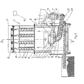
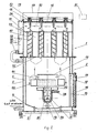
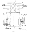
- the heating boiler ( fig. 1 and 2 ) consists of a cylindrical body, including an upper chamber 1 and a lower double-wall chamber 2, connected in a fixed position to one another by flanges, between which there is a heat-resistant gasket.
- the lower chamber 2 is constructed of concentrically positioned outer 3 and inner 4 bodies.
- the outer body 3 has a flat horizontal bottom 5.
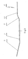
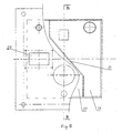
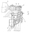
- the inner body 4 has a profile bottom 6 ( figs. 3 and 4 ), which is at a distance from bottom 5 of the outer body 3.
- the profile bottom 6 consists of a horizontal sector 7 and its two sides pass over into slanted rising sectors 8 and 9, one of which, 8, passes over into a second horizontal sector 10.
- the length of the central horizontal sector 7 is equal to the distance between the outer walls of the hollow door 17 and the combustion panel 18. Between the bottoms 5 and 6 are arranged the distance-ensuring elements 11. In this way space is formed between the outer body 3 and the inner body 4, which is connected with the inlet for the heat conductor.
- an opening which is closed with the inspection door 12, in front of which, to the inside, is positioned a movable screen 13 with possibility for rotating round its upper end.
- the inspection door 12 is constructed of heat-resistant material, with handles, made of heat-resistant material, and has an inspection opening 14, closed with cover 15.
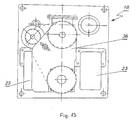
- the combustion panel 18 ( figs. 5 , 6 and 13 ) is a hollow door, whose inner space is divided into two separate chambers 19 and 20 by a diagonal barrier 21.
- One of the spaces of the hollow door 19, through an opening 22 in the outer wall of the combustion panel 18, is connected to a fan for secondary air 23.
- the other space 20, through a corresponding opening 24 in the outer wall of the combustion panel 18, is connected to a fan for primary air 25.
- a furnace which is a hollow horizontal combustion plate 26 ( figs. 8 and 9 ), with a central cylindrical opening 27, running through the whole height of combustion plate 26.
- a furnace which is a hollow horizontal combustion plate 26 ( figs. 8 and 9 ), with a central cylindrical opening 27, running through the whole height of combustion plate 26.
- Round the central opening 27, all over the upper surface 28 of the combustion plate 26 are formed a number of openings 29 in the shape of a frustum of a cone, turned with its smaller base downwards.
- the openings 29 are evenly distributed in circles, concentrically to the central opening 27, which ensures the complete combustion of the fed biofuel, with no risk of getting blocked.
- To the lower part of combustion plate 26 and concentrically to the central opening 27 is formed another opening 27'.
- the lower end of the central cylindrical opening 27 of the combustion plate 26 is connected to an inner tube 30 ( fig.10 ).
- the inner tube 30 consists of an elbow and a straight section, along the axis and along the whole length of which is mounted a screw 31, whose axis joins the horizontal at 3° to 8°, preferably 7°.
- a concentrical outer tube 32 encloses the inner tube 30.
- the space between the two tubes 30 and 32 is connected to the space of the combustion plate 26 through its second opening 27'.
- the inner tube 30 runs through the combustion panel 18. Above the upper end of inner tube 30 is connected a vertical furrow 33, which, through a fire-safety dose pump 34 is connected to the outlet of bunker 35 for biofuel.
- the back end of screw 31 is on bearings in a thrust strip 36, which closes the space of the inner tube 30.
- the thrust strip 36 is connected in a fixed position to the front part of dose pump 34.
- the screw 31 is driven by
- a heat-resistant tube 38 of stainless steel which is connected with its outer end to an ignition device 39, located sideward to and out of the combustion panel 18.
- the other end of tube 38 is situated in the space of inner tube 30, immediately under the central opening 27 of the combustion plate 26.
- a hollow ring-shaped airline 40 Coaxically, and at a distance above the upper surface 28 of the combustion plate 26, is positioned a hollow ring-shaped airline 40, over whose entire inner surface there are formed openings 41, set in parallel and horizontal rows. The diameter of the openings 41 is bigger with every ascending row than that of the preceding row.
- a reflecting disk 42 Above the hollow ring-shaped airline 40 is situated a reflecting disk 42.
- the width of the ring-shaped airline 40 has been so chosen, as to ensure the complete combustion and guiding of the flame to the center of the reflecting disk 42, creating a turbulent movement of the hot air along the walls of inner body 4 of lower chamber 2.
- the inner space of the ring-shaped airline 40 is connected to space 19 of the combustion panel 18, which, on its turn, is connected to the fan for secondary air 23.
- a waste-cleaning device 43 constructed as a screw.
- a guide tube 31' In the hollow-door wall 17, and coaxically to the screw 31 is installed, in a fixed position, a guide tube 31', along the axis of which runs the going out of the lower body 2 front end of the screw 31, ending above the waste bin 63.
- the end of guide-tube 31' is a dead-end, and before it, to the waste-bin's 63 side, is formed an opening for waste discharge.
- the screw 31 is on bearings at its both ends, correspondingly, at the dead-end of the guide-tube 31' and in the combustion panel 18.
- a heat exchanger with vertically positioned tubes.
- a reflecting plate 45 constructed as a three-layer plate, consisting of a base under which are placed a heat-resistant layer and a reflector of stainless sheet.
- the reflecting plate 45 has formed openings 46 and is connected in a fixed position to the upper body 1.
- the heat exchanger includes a number of vertical and parallel to one another smoke tubes 47, located under every opening 46 of the reflecting plate. In every smoke tube 47 is positioned a cleaner 48, every one of which is a coiled spiral of a stainless- steel profile of quadrangular section.
- each cleaner 48 ( fig.12 ) is connected with axis 49, which is on bearings in the outlet 46 of the reflecting plate 45.
- the upper end of axis 49 is connected in a fixed position with gear 50, positioned in the space above the reflecting plate 45. All gear wheels 50 are connected to a driver through a gear transmission.
- Smoke tubes 47 are connected in a fixed position to the upper chamber 1 through an upper mirror 51, and a lower mirror 52.
- the upper mirror 51 is positioned at some distance from the reflecting plate 45, at which, space 53 is formed for the flue gases.
- space 53 is formed for the flue gases.
- space 54 for the heat conductor is connected through a pipeline 55 to the space between the outer 3 and the inner 4 bodies of the lower chamber 2.
- a gas-turbine panel 56 ( fig. 11 ), which has an upper opening 57, to which a flue-gas fan is connected, and a lower opening 58, connected to a smoke off-take.
- an outlet for the heat conductor At one side of the gas-turbine panel 56 is situated an outlet for the heat conductor, and at its other side there is an inlet/outlet to/for other heat conductors.
- the gas-turbine panel 56 is equipped with a A- probe 59, positioned outside of the upper body 1 of the boiler, in the space before the upper opening 57.
- control openings 60 At both sides of the gas-turbine panel 56 there are formed control openings 60, two at each side, designated for transmitting signals from a pick-up device for the temperature of the heat conductor in the space 54, a transducer for the pressure of the heat conductor in the space 54, a pick-up device for the temperature of the outer wall of the upper chamber 1, and a pick-up device for preliminary chemical gases in the space of the nearest smoke tube 47. Every one of the enumerated pick-ups, which is not shown on the attached figures, is connected to the remote-control device 61.
- the remote-control device 61 is in connection with the A- probe 59, and with a detector 62 for smoke availability, located immediately by the lower opening 58 of the gas-turbine panel 56.
- the remote-control device 61 could be realized by the available at the market Universal regulator type 5711 OGC of TEM company, Switzerland.
- the construction of the boiler allows for easy service maintenance, as well as its easy transformation from a boiler of a certain capacity into a boiler of higher capacity, by simply replacing the hollow horizontal combustion plate 26, hollow ring-shaped airline 40 and reflecting disk 42, with other ones of the desired capacity.
- the area of the upper surface 28 of the hollow horizontal combustion plate 26 and the reflecting disk 42 is bigger.
- the inner diameter of the hollow ring-shaped airline 40 is increased proportionally to the hollow horizontal combustion plate 26. Increase is, also, the number of the openings 29 in the combustion plate 26 and the openings 41 in the hollow ring-shaped airline 40.
- the invention is constructed as a heating boiler of 100 KW.
- Doses of bio-fuel are fed from the biofuel bunker 35, through dose-pump 34, down the vertical furrow 33, at certain intervals, and they enter the back end of screw 31.
- Dose- pump 34 works according the set- by- the remote-control device 61 programme and discharges the dosed biofuel, which, under the pressure of its own weight, down along the vertical furrow 33, goes onto screw 31.
- the screw 31 conveys the biofuel to the central opening 27 of the hollow combustion plate 26, where it enters into contact with the fed by the ignition device 39, through heat-resistant tube 38, hot air. In seconds the biofuel ignites spontaneously.
- the smoke detector 62 switches on the smooth feeding of the primary air from fan 25.
- the air passes consecutively through chamber 20 of the combustion panel 18, the space between the tubes 30 and 32, the opening 27', and goes into the cavity of the hollow horizontal plate 26, from where it goes out through the cone-openings 29 on its upper surface 28.
- the screw 31 starts to smoothly take out the biofuel and to push upwards the already ignited biofuel upon the upper surface 28 of the combustion plate 26. That even and smooth discharge of the biofuel allows for discharging the burning material in the shape of a circle upon the upper surface 28 of the combustion plate 26.
- the fact that the screw's 31 axis joins the horizontal at an angle of 3° to 6° accounts for the avoiding the clogging of the screw 31 and ensures the even and smooth feeding of the biofuel to the surface 28 of the hollow horizontal combustion plate 26.
- the supplied through chamber 19 of the combustion panel 18 secondary air goes into the interior of the hollow ring-shaped airline 40, and then out through its openings 41, and gets into contact with the ascending flow of burning flue gases, in which the non-burnt particles of biofuel are increased, which ensures their additional complete combustion and further increases the temperature of the flue gases, and from it - the heat quantity released to the heat conductor.
- the ring-shaped airline 40 ensures directing the flame to the centre of the reflecting disk 42.
- the going upwards flow of burning flue gases is, under the pressure, directed to the reflecting disc 42, which diverts it and creates turbulent movement, directed to the lower part of the internal body 4 of the lower chamber 2, at which their heat is released to the heat conductor, located in the space between the outer 3 and inner 4 bodies of the lower chamber 2.
- the flue gases take an upward direction under the existing pressure and as a result of the created by the smoke-offtake natural draught through opening 58, pass through the smoke tubes 47, and before reaching the smoke offtake, release their heat to the already heated in the space between the outer 3 and inner 4 bodies heat conductor, entering the space 54 between the smoke tubes 47 through pipeline 55.
- the movement of the spiral-like cleaners 48 additionally improves the heat- releasing through the walls of the smoke tubes 47 due to the fact that, on the hand, keeps their inner surface clean of soot through continuously scraping them by the sharp edges of the moving profile 48, and on the other hand, creates a turbulent movement of the moving upwards in the smoke tubes 47 flow of flue gases, which lengthens its way.
- the heated heat conductor is led out of the boiler to a user-unit, for example, a local heating installation, through an outlet in the upper chamber 1.
- the A- probe 59 supplies data for chemical analysis of the flue gases to the remote-control device 61, which, depending on the established chemical composition and the pre-set parameters, regulates the air quantity, fed by the fans 23 and 25.
- the remote controlling device 61 switches on the not-shown on the figures fan for flue gases for sucking and discharging them into the atmosphere.
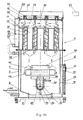
- the controlling device 61 sends a signal to the fan for flue gases, switching it into a back-movement regime, which causes reverse feeding of the flue gases through space 53 and the smoke tubes 47 in the lower body 2, where, due to the increased quantity of oxygen in the fed secondary air, is carried out their complete combustion and achievement of the pre-set norms ( fig.14 ).
- the heating boiler has a reduced quantity released- into- the atmosphere harmful emissions, resulting from the ensured programmed and more complete combustion of the biofuel, due to the in-built A- probe 59, sending a signal to the remote- controlling device 61, which analyses it and emits controlling signals to the fans for the flue gases in the cases when they are not within the pre-set parameters.
- the waste from the combusted biofuel is continuously pushed out to the periphery of combustion plate 26 by the entering through the central opening 27 combusting biofuel, and from there, sliding down the slanted sections 8 and 9 of the profile bottom 6 of the inner body 4, falls onto the central horizontal sector 7, from where, by means of cleaning device 43, for example a screw, is conveyed to the waste bin 63.
- the heating boiler whose outlet for the heat conductor is connected to an user, it is possible to lead out, from the outlet for other heat resources, part of the warmed heat conductor to an additional user. If the heating boiler, connected to the user, is not in use at the moment, it is possible, through the same inlet, to supply to the user (a local heating network) in space 54, a heat conductor from another source, e.g. a sun panel, with no need of disassembling and installing new links to the user.
- a local heating network e.g. a sun panel
Landscapes
- Engineering & Computer Science (AREA)
- Chemical & Material Sciences (AREA)
- Combustion & Propulsion (AREA)
- Mechanical Engineering (AREA)
- General Engineering & Computer Science (AREA)
- Physics & Mathematics (AREA)
- Thermal Sciences (AREA)
- Solid-Fuel Combustion (AREA)
Claims (9)
- Une chaudière de chauffage, qui se compose d'un enduit de corps en matière isolante, recouvert d'un couvercle, à la partie inférieure de laquelle est prévu un foyer sous la partie inférieure de la cheminée d'une vis d'alimentation biofuel- est prévu, qui est relié avec un entraînement mécanisme, et le foyer a un certain nombre d'ouvertures à travers lesquelles il est connecté à une source d'air primaire, et l'extérieur du corps de la chaudière au-dessus de la partie avant de la vis un bunker de biocarburant est prévu un échangeur de chaleur, reliée à la partie supérieure du corps, est monté au-dessus du foyer, traversé par un conducteur de chaleur, l'échangeur de chaleur présente des canaux verticaux pour les gaz de combustion, au cours de laquelle, au-dessus du foyer et avant l'entrée de l'échangeur de chaleur et de manière coaxiale à l'âtre une corps en forme d'anneau creux est situé, et au-dessus de la surface cylindrique intérieure de laquelle sont orifices de sortie est situé, l'espace du corps en forme d'anneau creux est relié à une source d'air secondaire, et au-dessus de la partie supérieure de l'échangeur de chaleur d'un métal plaque réfléchissante est montée, et l'espace formé entre eux est reliée à la sortie des effluents gazeux, caractérisé par le fait que le corps est cylindrique et construit par connectée dans une position fixe une haut (1) et inférieur (2) chambres, la chambre inférieure (2) est à double paroi et est constituée d'un externe (3) et d'un interieur (4) corps, le corps externe positionné de manière concentrique extérieur (3) présente un fond plat horizontal (5), tandis que le corps intérieur (4) comporte un fond de profil (6), qui est à une distance du fond (5) du corps extérieur (3), et entre eux un espace est formé, qui est reliée à l'entrée du conducteur de chaleur, à proximité du fond de profil (6), dans la paroi de la chambre inférieure (2), une ouverture est formée, qui est fermé par une porte d'inspection (12) avec un écran mobile située en avant de celui-ci (13), diamétralement opposées, et des deux côtés de la trappe de visite (12), dans la chambre inférieure (2) paroi, sont formées deux ouvertures identiques (16), dont l'une est fermée par une porte creuse (17), tandis que l'autre est fermée par un panneau de combustion (18) et le panneau de combustion est une porte creux, dont l'espace intérieur est divisé en deux chambres séparées (19) et (20) par une barrière diagonale (21), l'un des espaces (19) de la porte creux de la plaque de combustion (18), à travers une ouverture (22) sur la paroi extérieure du panneau de combustion (18), est reliée à la source d'air secondaire (23), et l'autre espace (20), à travers une ouverture correspondante (24) sur la paroi extérieure de la plaque de combustion (18), est reliée à la source d'air primaire (25), et le foyer est une plaque horizontale creux de combustion (26) avec une ouverture cylindrique centrale (27), qui traverse toute la hauteur de la plaque de combustion (26), sur le côté inférieur de la plaque de combustion creux (26), concentrique par rapport à l'ouverture cylindrique (27) une deuxième ouverture (27 ') est destiné, et le nombre d'ouvertures du four sont formées sur la surface supérieure (28) de la plaque de combustion horizontal creux (26), l'extrémité inférieure de l'ouverture cylindrique centrale (27) de la plaque horizontal creux de combustion (26) est relié à un tube intérieur (30), qui se compose d'un coude et une section rectiligne, le long de l'axe et sur toute la longueur de laquelle est montée la vis d'alimentation biofuel- (31), et l'axe de l'intersection de l'horizontale à 3 ° à 8 °, le tube intérieur (30) est enfermé concentriquement par un tube extérieur (32), et l'espace formé entre eux est relié à la soufflante pour l'air primaire (25), et l'espace entre les deux tubes (30) et (32) est en liaison avec l'espace intérieur, aussi, de la plaque creuse horizontale de combustion (26) à travers sa deuxième ouverture (27 '), le tube intérieur traverse le panneau de combustion (18), et dernière son extrémité arrière est raccordée un sillon vertical (33), qui, bien que d'un feu La pompe de la sécurité (34), est relié à la sortie du bunker biofuel- (35), et à travers le panneau de combustion (18) exécute un tuyau (38), qui est relié à son extrémité extérieure à un dispositif d'allumage (39), situé à l'extérieur du corps de la chaudière, tandis que son autre extrémité est située dans l'espace de la conduite interne (30), immédiatement sous l'ouverture centrale (27) de la creux plaque de combustion horizontal (26), un disque réfléchissant (42) est monté au-dessus de la ligne aérienne creux en forme d'anneau (40) et les ouvertures (41) du disque (40) sont disposés en rangées horizontales parallèles, et le diamètre de chaque ligne ascendante qui suit est plus grand que le diamètre de la précédente, et l'échangeur de chaleur est monté dans la chambre supérieure (1), à laquelle l'espace intérieur de la compagnie aérienne en forme d'anneau (40) est relié à un ventilateur pour l'air secondaire (23) à travers l'espace (19) de la plaque de combustion (18), et en dessous du couvercle (44), et à une certaine distance à partir de l'échangeur de chaleur, une plaque réfléchissante (45) avec des ouvertures formées (46) est placé, relié à une position fixe à la chambre supérieure (1) et l'échangeur de chaleur est constitué d'un certain nombre de colonnes et parallèlement les uns aux autres fumées tubes (47) figurant en dessous de chaque ouverture (46), et chaque tube de fumée (47) est positionné une tour ax rotation propre (48), et les tubes de fumée (47) sont reliés dans une position fixe à un miroir supérieur (51), qui est positionné à une certaine distance de la plaque réfléchissante (45), entre lesquelles est formé un espace (53) pour prélever les gaz de combustion, et les tubes de fumée (47) sont également connectés dans une position fixe sur le miroir inférieur (52), et la forme entre les deux miroirs (51) et (52) l'espace (54) pour le conducteur de chaleur est relié par un tube (55) à l'espace entre la partie extérieure (3) et l'intérieur (4) corps de la chambre inférieure (2), et un panneau de turbine à gaz (56) est positionné dans la partie arrière de la chambre supérieure (1), lequel panneau de turbine à gaz comporte une ouverture supérieure (57), qui est relié à un ventilateur de gaz de fumée et une ouverture inférieure (58), relié à l'espace (53) pour les gaz de combustion, qui est relié à un prélèvement de fumées, et le panneau de turbine à gaz (56) est équipé d'une sonde λ- (59), positionnée dans l'espace devant l'ouverture supérieure (57) et à l'extérieur de la partie supérieure du corps (1) des ouvertures de la chaudière, et au niveau des deux côtés du panneau de la turbine à gaz (56) y sont formés commande (60), deux de chaque côté, désignés pour transmettre des signaux provenant d'un dispositif de ramassage pour la température du conducteur de chaleur dans l'espace (54), un transducteur de la pression du caloporteur dans l'espace (54), un dispositif de ramassage pour la température de la paroi extérieure de la chambre supérieure (1), un dispositif de ramassage pour préliminaires gaz chimiques de la l'espace du tube de fumée la plus proche (47), et chacun des capteurs énumérés est relié à un dispositif de télécommande (61), qui est en liaison avec la sonde λ- (59) et un détecteur (62) pour disponibilité de fumée, situé immédiatement par l'ouverture inférieure (58).
- Chaudière de chauffage selon la revendication 1, caractérisé par le fait que le fond de profil (6) est constitué d'un secteur horizontal central (7), dont les deux parois passer en oblique, passant secteurs (8) et (9), dont l'un (8) passe dans un deuxième secteur horizontal (10), et la longueur du secteur central horizontal (7) est égale à la distance entre les parois extérieures de la porte creux (17) et le panneau de combustion (18).
- Chaudière de chauffage selon la revendication 1, caractérisé par le fait que chacun des produits de nettoyage (48) est un profil en spirale enroulé en acier inoxydable, et la partie supérieure de l'aspirateur (48) dans l'espace au-dessus de la plaque réfléchissante (45) est relié dans une position fixe à une roue d'engrenage (50), et toutes les roues d'engrenage (50) sont reliés à un moteur par l'intermédiaire d'une transmission.
- Chaudière de chauffage selon la revendication 1, caractérisé par le fait que près du secteur horizontal (7) du fond (6) du corps intérieur (4) et dans le tube extérieur (32), se trouve un usées Dispositif (43), réalisé sous la forme d'une vis de nettoyage, et à travers la paroi creuse porte (17), coaxically de la vis (31), est installé un tube de guidage (31 '), le long de l'axe court de l'extrémité avant de la vis (31) qui sort de la partie inférieure du corps (2), qui atteint la poubelle (63) et (31 ') extrémité de tube-guide est une impasse, et avant elle, à de déchets-bin (63) côté, il ya une ouverture pour l'évacuation des déchets, et la vis (31) est sur paliers au niveau de ses deux extrémités, de manière correspondante, à l'impasse du tube-guide (31 ') et le panneau de combustion (18).
- Chaudière de chauffage selon la revendication 1, caractérisé par le fait que près du secteur horizontal (7) sur le fond (6) du corps intérieur (4) et dans le tube extérieur (32) est positionné à une cendre de nettoyage Dispositif (43), réalisé sous la forme d'un dispositif de succion sous vide, reliée à la poubelle de déchets (63).
- Chaudière de chauffage selon la revendication 1, caractérisé par le fait que le détecteur de fumée (62) est relié au dispositif pour l'allumage initial (39) par l'intermédiaire d'un dispositif de télécommande (61).
- Chaudière de chauffage selon la revendication 1, caractérisé par le fait que la plaque réfléchissante (45) est réalisé sous forme de plaque à trois couches, composée d'une base qui est disposée sous une couche résistant à la température et un réflecteur en inox feuille.
- Chaudière de chauffage selon la revendication 3, caractérisé par le fait que (48) le profil de l'aspirateur a une section quadrangulaire, dont les bords de deux sont en contact étroit avec la surface intérieure du tube de fumée (47).
- Chaudière de chauffage selon la revendication 1, caractérisé par le fait que le nombre d'ouvertures (29) sur la plaque de combustion horizontal creux (26) sont répartis uniformément dans concentrique à l'ouverture centrale (27) des cercles, et sont sous la la forme d'un tronc de cône avec sa petite base vers le bas
Applications Claiming Priority (2)
| Application Number | Priority Date | Filing Date | Title |
|---|---|---|---|
| BG109653A BG66233B1 (bg) | 2006-08-25 | 2006-08-25 | Отоплителен котел |
| PCT/BG2007/000019 WO2008022412A1 (fr) | 2006-08-25 | 2007-08-21 | Chaudière |
Publications (2)
| Publication Number | Publication Date |
|---|---|
| EP2054675A1 EP2054675A1 (fr) | 2009-05-06 |
| EP2054675B1 true EP2054675B1 (fr) | 2015-07-15 |
Family
ID=37603032
Family Applications (1)
| Application Number | Title | Priority Date | Filing Date |
|---|---|---|---|
| EP07800360.5A Active EP2054675B1 (fr) | 2006-08-25 | 2007-08-21 | Chaudière |
Country Status (3)
| Country | Link |
|---|---|
| EP (1) | EP2054675B1 (fr) |
| BG (1) | BG66233B1 (fr) |
| WO (1) | WO2008022412A1 (fr) |
Cited By (3)
| Publication number | Priority date | Publication date | Assignee | Title |
|---|---|---|---|---|
| RU168895U1 (ru) * | 2016-03-24 | 2017-02-27 | Денис Александрович Папилин | Котел водогрейный |
| RU177020U1 (ru) * | 2017-04-06 | 2018-02-06 | Общество с ограниченной ответственностью "Светлобор" | Камера сгорания твердотопливного котла |
| WO2018186769A1 (fr) * | 2017-04-06 | 2018-10-11 | Общество с ограниченной ответственностью "Светлобор" | Chambre de combustion de chaudière à combustible solide |
Families Citing this family (15)
| Publication number | Priority date | Publication date | Assignee | Title |
|---|---|---|---|---|
| AT507528B1 (de) * | 2008-10-09 | 2013-01-15 | Kalkgruber Johann | Wärmetauscher für einen heizkessel |
| SE534371C2 (sv) * | 2009-01-30 | 2011-07-26 | Ariterm Sweden Ab | Rengöringsanordning för pelletseldade värmekaminer |
| AT508157B1 (de) * | 2009-08-04 | 2010-11-15 | Schiefer Erwin | Vorrichtung zum abreinigen eines wärmetauschers |
| IT1400646B1 (it) * | 2010-07-01 | 2013-06-28 | Jolly Mec Caminetti S P A | Dispositivo per l'immissione del combustibile in un bruciatore |
| EP2410279A1 (fr) | 2010-07-21 | 2012-01-25 | Thomas Hipp | Echangeur thermique nécessitant peu d'entretien avec des racleurs rotatifs |
| ITVR20130151A1 (it) * | 2013-06-27 | 2014-12-28 | Gruppo Piazzetta Spa | Dispositivo per la pulizia di tubi di fumo |
| EP3240975B1 (fr) * | 2014-12-29 | 2018-12-12 | Felino-Fundição de Const. Mecânicas, SA | Chaudière d'alimentation pour conduites d'eau de chauffage ou d'autres fluides thermiques dotée d'un échangeur de chaleur modulaire et d'un système de nettoyage |
| CN105180151A (zh) * | 2015-10-13 | 2015-12-23 | 灌阳县鸿运矿山设备有限公司 | 一种生物质燃料机 |
| PL71256Y1 (pl) * | 2017-11-13 | 2020-02-28 | P P H Kostrzewa Spolka Jawna | Kocioł grzewczy |
| CN109751884B (zh) * | 2019-01-26 | 2020-07-28 | 福建省德化县新顺机械有限公司 | 一种陶瓷窑炉废热利用装置 |
| PL437563A1 (pl) * | 2021-04-13 | 2022-10-17 | Łukasz Mocek | Kocioł centralnego ogrzewania |
| CN113340126B (zh) * | 2021-05-28 | 2022-11-04 | 内蒙古大唐国际托克托发电有限责任公司 | 直接空冷机组空冷岛防风装置 |
| CN115900064B (zh) * | 2022-11-27 | 2025-04-22 | 安徽自然使者环保科技有限公司 | 一种振荡生热高温热风机 |
| CN117213060A (zh) * | 2023-09-25 | 2023-12-12 | 江苏四方清洁能源装备制造有限公司 | 一种水火管复合型强化传热冷凝式燃气锅炉 |
| CN118324393B (zh) * | 2024-06-13 | 2024-09-10 | 洛玻集团洛阳龙海电子玻璃有限公司 | 一种玻璃熔窑烟道和蓄热室易积灰处的灰清洁方法 |
Family Cites Families (4)
| Publication number | Priority date | Publication date | Assignee | Title |
|---|---|---|---|---|
| DE8220521U1 (de) * | 1982-07-17 | 1983-06-09 | Wagner, Albert, 6200 Wiesbaden | Heizkessel |
| CH674680A5 (en) * | 1987-12-23 | 1990-06-29 | Landis & Gyr Betriebs Ag | Variable gas flow device for gas sensor - uses connection pipe coupled to press point ensuring pressure difference at sensor input |
| DE9000738U1 (de) * | 1990-01-24 | 1990-05-03 | Ruhrkohle Ag, 4300 Essen | Nachschaltheizfläche für Heizkessel |
| WO2006008762A1 (fr) * | 2004-07-16 | 2006-01-26 | Filippo Antonio Di Cecilia | Appareil de chauffage a granules avec production d'eau et d'air chauds |
-
2006
- 2006-08-25 BG BG109653A patent/BG66233B1/bg unknown
-
2007
- 2007-08-21 WO PCT/BG2007/000019 patent/WO2008022412A1/fr not_active Ceased
- 2007-08-21 EP EP07800360.5A patent/EP2054675B1/fr active Active
Cited By (3)
| Publication number | Priority date | Publication date | Assignee | Title |
|---|---|---|---|---|
| RU168895U1 (ru) * | 2016-03-24 | 2017-02-27 | Денис Александрович Папилин | Котел водогрейный |
| RU177020U1 (ru) * | 2017-04-06 | 2018-02-06 | Общество с ограниченной ответственностью "Светлобор" | Камера сгорания твердотопливного котла |
| WO2018186769A1 (fr) * | 2017-04-06 | 2018-10-11 | Общество с ограниченной ответственностью "Светлобор" | Chambre de combustion de chaudière à combustible solide |
Also Published As
| Publication number | Publication date |
|---|---|
| WO2008022412A1 (fr) | 2008-02-28 |
| BG66233B1 (bg) | 2012-07-31 |
| BG109653A (bg) | 2006-12-29 |
| EP2054675A1 (fr) | 2009-05-06 |
Similar Documents
| Publication | Publication Date | Title |
|---|---|---|
| EP2054675B1 (fr) | Chaudière | |
| US8322331B2 (en) | Burner for combustion of fuel in pellet or granular form | |
| US7954438B2 (en) | Wood fired boiler | |
| CN113710128A (zh) | 用于颗粒烤架的燃烧室 | |
| EP2753878B1 (fr) | Dispositif de combustion et procédé pour la combustion de combustible solide granulaire | |
| US20130269678A1 (en) | Anti-Scorification Oven | |
| US9995489B2 (en) | Pellet stove | |
| US7861707B2 (en) | Gravity feed natural draft pellet stove | |
| JP2017075721A (ja) | 燃焼装置 | |
| KR101371235B1 (ko) | 연소판을 청소하는 브러쉬를 가지는 펠릿보일러 및 이를 이용한 보일러 운전방법 | |
| KR20120108679A (ko) | 펠릿과 기름겸용 보일러 | |
| EP2615369B1 (fr) | Dispositif de chauffage | |
| KR101852908B1 (ko) | 이동식 화격자가 구비된 펠릿보일러 | |
| KR101224631B1 (ko) | 펠릿보일러 | |
| KR101448100B1 (ko) | 하이브리드 보일러 | |
| EP2144001B1 (fr) | Methode de nettoyage de l'âtre d'un appareil de chauffage | |
| EP4227580A1 (fr) | Foyer prévu pour des combustibles solides avec dispositif multi-combustible disposé dans son lieu de combustion | |
| KR20160111708A (ko) | 재의 비산이 방지되고 재의 청소가 용이한 펠릿난로 | |
| KR102023110B1 (ko) | 화목 펠릿 난로 | |
| GB2447952A (en) | Solid fuel boiler | |
| RU51178U1 (ru) | Водогрейная газотрубная установка для сжигания отходов растительного происхождения | |
| KR101821308B1 (ko) | 옥수수 연료를 이용한 구이용 화덕장치 | |
| KR102297258B1 (ko) | 유해연소가스를 제거 가능한 펠릿 난로 | |
| JP3197127U (ja) | ペレット燃焼装置 | |
| EP1983258A2 (fr) | Brûleur à bois |
Legal Events
| Date | Code | Title | Description |
|---|---|---|---|
| PUAI | Public reference made under article 153(3) epc to a published international application that has entered the european phase |
Free format text: ORIGINAL CODE: 0009012 |
|
| 17P | Request for examination filed |
Effective date: 20081209 |
|
| AK | Designated contracting states |
Kind code of ref document: A1 Designated state(s): AT BE BG CH CY CZ DE DK EE ES FI FR GB GR HU IE IS IT LI LT LU LV MC MT NL PL PT RO SE SI SK TR |
|
| AX | Request for extension of the european patent |
Extension state: AL BA HR MK RS |
|
| RAX | Requested extension states of the european patent have changed |
Extension state: AL Payment date: 20081209 Extension state: MK Payment date: 20081209 Extension state: BA Payment date: 20081209 Extension state: RS Payment date: 20081209 |
|
| RIC1 | Information provided on ipc code assigned before grant |
Ipc: F23B 40/04 20060101ALI20150123BHEP Ipc: F24H 1/28 20060101AFI20150123BHEP Ipc: F23K 3/14 20060101ALI20150123BHEP Ipc: F24H 9/00 20060101ALI20150123BHEP Ipc: F28G 3/10 20060101ALI20150123BHEP |
|
| GRAP | Despatch of communication of intention to grant a patent |
Free format text: ORIGINAL CODE: EPIDOSNIGR1 |
|
| INTG | Intention to grant announced |
Effective date: 20150320 |
|
| GRAS | Grant fee paid |
Free format text: ORIGINAL CODE: EPIDOSNIGR3 |
|
| GRAA | (expected) grant |
Free format text: ORIGINAL CODE: 0009210 |
|
| AK | Designated contracting states |
Kind code of ref document: B1 Designated state(s): AT BE BG CH CY CZ DE DK EE ES FI FR GB GR HU IE IS IT LI LT LU LV MC MT NL PL PT RO SE SI SK TR |
|
| AX | Request for extension of the european patent |
Extension state: AL BA MK RS |
|
| REG | Reference to a national code |
Ref country code: CH Ref legal event code: EP Ref country code: GB Ref legal event code: FG4D |
|
| REG | Reference to a national code |
Ref country code: IE Ref legal event code: FG4D |
|
| REG | Reference to a national code |
Ref country code: FR Ref legal event code: PLFP Year of fee payment: 9 |
|
| REG | Reference to a national code |
Ref country code: AT Ref legal event code: REF Ref document number: 737008 Country of ref document: AT Kind code of ref document: T Effective date: 20150815 |
|
| REG | Reference to a national code |
Ref country code: DE Ref legal event code: R096 Ref document number: 602007042175 Country of ref document: DE |
|
| PGFP | Annual fee paid to national office [announced via postgrant information from national office to epo] |
Ref country code: FR Payment date: 20150813 Year of fee payment: 9 |
|
| REG | Reference to a national code |
Ref country code: NL Ref legal event code: MP Effective date: 20150715 |
|
| REG | Reference to a national code |
Ref country code: LT Ref legal event code: MG4D |
|
| PG25 | Lapsed in a contracting state [announced via postgrant information from national office to epo] |
Ref country code: GR Free format text: LAPSE BECAUSE OF FAILURE TO SUBMIT A TRANSLATION OF THE DESCRIPTION OR TO PAY THE FEE WITHIN THE PRESCRIBED TIME-LIMIT Effective date: 20151016 Ref country code: FI Free format text: LAPSE BECAUSE OF FAILURE TO SUBMIT A TRANSLATION OF THE DESCRIPTION OR TO PAY THE FEE WITHIN THE PRESCRIBED TIME-LIMIT Effective date: 20150715 Ref country code: LT Free format text: LAPSE BECAUSE OF FAILURE TO SUBMIT A TRANSLATION OF THE DESCRIPTION OR TO PAY THE FEE WITHIN THE PRESCRIBED TIME-LIMIT Effective date: 20150715 Ref country code: LV Free format text: LAPSE BECAUSE OF FAILURE TO SUBMIT A TRANSLATION OF THE DESCRIPTION OR TO PAY THE FEE WITHIN THE PRESCRIBED TIME-LIMIT Effective date: 20150715 |
|
| PG25 | Lapsed in a contracting state [announced via postgrant information from national office to epo] |
Ref country code: ES Free format text: LAPSE BECAUSE OF FAILURE TO SUBMIT A TRANSLATION OF THE DESCRIPTION OR TO PAY THE FEE WITHIN THE PRESCRIBED TIME-LIMIT Effective date: 20150715 Ref country code: SE Free format text: LAPSE BECAUSE OF FAILURE TO SUBMIT A TRANSLATION OF THE DESCRIPTION OR TO PAY THE FEE WITHIN THE PRESCRIBED TIME-LIMIT Effective date: 20150715 Ref country code: PT Free format text: LAPSE BECAUSE OF FAILURE TO SUBMIT A TRANSLATION OF THE DESCRIPTION OR TO PAY THE FEE WITHIN THE PRESCRIBED TIME-LIMIT Effective date: 20151116 Ref country code: PL Free format text: LAPSE BECAUSE OF FAILURE TO SUBMIT A TRANSLATION OF THE DESCRIPTION OR TO PAY THE FEE WITHIN THE PRESCRIBED TIME-LIMIT Effective date: 20150715 |
|
| REG | Reference to a national code |
Ref country code: CH Ref legal event code: PL |
|
| REG | Reference to a national code |
Ref country code: DE Ref legal event code: R097 Ref document number: 602007042175 Country of ref document: DE |
|
| PG25 | Lapsed in a contracting state [announced via postgrant information from national office to epo] |
Ref country code: CZ Free format text: LAPSE BECAUSE OF FAILURE TO SUBMIT A TRANSLATION OF THE DESCRIPTION OR TO PAY THE FEE WITHIN THE PRESCRIBED TIME-LIMIT Effective date: 20150715 Ref country code: MC Free format text: LAPSE BECAUSE OF FAILURE TO SUBMIT A TRANSLATION OF THE DESCRIPTION OR TO PAY THE FEE WITHIN THE PRESCRIBED TIME-LIMIT Effective date: 20150715 Ref country code: IT Free format text: LAPSE BECAUSE OF FAILURE TO SUBMIT A TRANSLATION OF THE DESCRIPTION OR TO PAY THE FEE WITHIN THE PRESCRIBED TIME-LIMIT Effective date: 20150715 Ref country code: LI Free format text: LAPSE BECAUSE OF NON-PAYMENT OF DUE FEES Effective date: 20150831 Ref country code: EE Free format text: LAPSE BECAUSE OF FAILURE TO SUBMIT A TRANSLATION OF THE DESCRIPTION OR TO PAY THE FEE WITHIN THE PRESCRIBED TIME-LIMIT Effective date: 20150715 Ref country code: CH Free format text: LAPSE BECAUSE OF NON-PAYMENT OF DUE FEES Effective date: 20150831 Ref country code: SK Free format text: LAPSE BECAUSE OF FAILURE TO SUBMIT A TRANSLATION OF THE DESCRIPTION OR TO PAY THE FEE WITHIN THE PRESCRIBED TIME-LIMIT Effective date: 20150715 Ref country code: DK Free format text: LAPSE BECAUSE OF FAILURE TO SUBMIT A TRANSLATION OF THE DESCRIPTION OR TO PAY THE FEE WITHIN THE PRESCRIBED TIME-LIMIT Effective date: 20150715 |
|
| REG | Reference to a national code |
Ref country code: AT Ref legal event code: UEP Ref document number: 737008 Country of ref document: AT Kind code of ref document: T Effective date: 20150715 |
|
| PLBE | No opposition filed within time limit |
Free format text: ORIGINAL CODE: 0009261 |
|
| STAA | Information on the status of an ep patent application or granted ep patent |
Free format text: STATUS: NO OPPOSITION FILED WITHIN TIME LIMIT |
|
| PG25 | Lapsed in a contracting state [announced via postgrant information from national office to epo] |
Ref country code: RO Free format text: LAPSE BECAUSE OF FAILURE TO SUBMIT A TRANSLATION OF THE DESCRIPTION OR TO PAY THE FEE WITHIN THE PRESCRIBED TIME-LIMIT Effective date: 20150715 |
|
| REG | Reference to a national code |
Ref country code: IE Ref legal event code: MM4A |
|
| 26N | No opposition filed |
Effective date: 20160418 |
|
| GBPC | Gb: european patent ceased through non-payment of renewal fee |
Effective date: 20151015 |
|
| PG25 | Lapsed in a contracting state [announced via postgrant information from national office to epo] |
Ref country code: IS Free format text: LAPSE BECAUSE OF FAILURE TO SUBMIT A TRANSLATION OF THE DESCRIPTION OR TO PAY THE FEE WITHIN THE PRESCRIBED TIME-LIMIT Effective date: 20150715 |
|
| PG25 | Lapsed in a contracting state [announced via postgrant information from national office to epo] |
Ref country code: GB Free format text: LAPSE BECAUSE OF NON-PAYMENT OF DUE FEES Effective date: 20151015 Ref country code: IE Free format text: LAPSE BECAUSE OF NON-PAYMENT OF DUE FEES Effective date: 20150821 |
|
| PG25 | Lapsed in a contracting state [announced via postgrant information from national office to epo] |
Ref country code: SI Free format text: LAPSE BECAUSE OF FAILURE TO SUBMIT A TRANSLATION OF THE DESCRIPTION OR TO PAY THE FEE WITHIN THE PRESCRIBED TIME-LIMIT Effective date: 20150715 |
|
| REG | Reference to a national code |
Ref country code: AT Ref legal event code: MM01 Ref document number: 737008 Country of ref document: AT Kind code of ref document: T Effective date: 20150821 |
|
| PGFP | Annual fee paid to national office [announced via postgrant information from national office to epo] |
Ref country code: DE Payment date: 20160823 Year of fee payment: 10 |
|
| PG25 | Lapsed in a contracting state [announced via postgrant information from national office to epo] |
Ref country code: AT Free format text: LAPSE BECAUSE OF NON-PAYMENT OF DUE FEES Effective date: 20150821 |
|
| PG25 | Lapsed in a contracting state [announced via postgrant information from national office to epo] |
Ref country code: MT Free format text: LAPSE BECAUSE OF FAILURE TO SUBMIT A TRANSLATION OF THE DESCRIPTION OR TO PAY THE FEE WITHIN THE PRESCRIBED TIME-LIMIT Effective date: 20150715 |
|
| REG | Reference to a national code |
Ref country code: FR Ref legal event code: ST Effective date: 20170428 |
|
| PG25 | Lapsed in a contracting state [announced via postgrant information from national office to epo] |
Ref country code: BG Free format text: LAPSE BECAUSE OF FAILURE TO SUBMIT A TRANSLATION OF THE DESCRIPTION OR TO PAY THE FEE WITHIN THE PRESCRIBED TIME-LIMIT Effective date: 20150715 Ref country code: HU Free format text: LAPSE BECAUSE OF FAILURE TO SUBMIT A TRANSLATION OF THE DESCRIPTION OR TO PAY THE FEE WITHIN THE PRESCRIBED TIME-LIMIT; INVALID AB INITIO Effective date: 20070821 |
|
| PG25 | Lapsed in a contracting state [announced via postgrant information from national office to epo] |
Ref country code: NL Free format text: LAPSE BECAUSE OF FAILURE TO SUBMIT A TRANSLATION OF THE DESCRIPTION OR TO PAY THE FEE WITHIN THE PRESCRIBED TIME-LIMIT Effective date: 20150715 Ref country code: CY Free format text: LAPSE BECAUSE OF FAILURE TO SUBMIT A TRANSLATION OF THE DESCRIPTION OR TO PAY THE FEE WITHIN THE PRESCRIBED TIME-LIMIT Effective date: 20150715 |
|
| PG25 | Lapsed in a contracting state [announced via postgrant information from national office to epo] |
Ref country code: FR Free format text: LAPSE BECAUSE OF NON-PAYMENT OF DUE FEES Effective date: 20160831 Ref country code: BE Free format text: LAPSE BECAUSE OF NON-PAYMENT OF DUE FEES Effective date: 20150831 |
|
| PG25 | Lapsed in a contracting state [announced via postgrant information from national office to epo] |
Ref country code: TR Free format text: LAPSE BECAUSE OF FAILURE TO SUBMIT A TRANSLATION OF THE DESCRIPTION OR TO PAY THE FEE WITHIN THE PRESCRIBED TIME-LIMIT Effective date: 20150715 |
|
| PG25 | Lapsed in a contracting state [announced via postgrant information from national office to epo] |
Ref country code: LU Free format text: LAPSE BECAUSE OF NON-PAYMENT OF DUE FEES Effective date: 20150821 |
|
| REG | Reference to a national code |
Ref country code: DE Ref legal event code: R119 Ref document number: 602007042175 Country of ref document: DE |
|
| PG25 | Lapsed in a contracting state [announced via postgrant information from national office to epo] |
Ref country code: DE Free format text: LAPSE BECAUSE OF NON-PAYMENT OF DUE FEES Effective date: 20180301 |