EP2055155B1 - Appareil de commande pour vehicule automobile - Google Patents
Appareil de commande pour vehicule automobile Download PDFInfo
- Publication number
- EP2055155B1 EP2055155B1 EP07817672A EP07817672A EP2055155B1 EP 2055155 B1 EP2055155 B1 EP 2055155B1 EP 07817672 A EP07817672 A EP 07817672A EP 07817672 A EP07817672 A EP 07817672A EP 2055155 B1 EP2055155 B1 EP 2055155B1
- Authority
- EP
- European Patent Office
- Prior art keywords
- circuit carrier
- opening
- foil conductor
- housing lid
- conductor strip
- Prior art date
- Legal status (The legal status is an assumption and is not a legal conclusion. Google has not performed a legal analysis and makes no representation as to the accuracy of the status listed.)
- Active
Links
Images


Classifications
-
- B—PERFORMING OPERATIONS; TRANSPORTING
- B60—VEHICLES IN GENERAL
- B60R—VEHICLES, VEHICLE FITTINGS, OR VEHICLE PARTS, NOT OTHERWISE PROVIDED FOR
- B60R16/00—Electric or fluid circuits specially adapted for vehicles and not otherwise provided for; Arrangement of elements of electric or fluid circuits specially adapted for vehicles and not otherwise provided for
- B60R16/02—Electric or fluid circuits specially adapted for vehicles and not otherwise provided for; Arrangement of elements of electric or fluid circuits specially adapted for vehicles and not otherwise provided for electric constitutive elements
- B60R16/023—Electric or fluid circuits specially adapted for vehicles and not otherwise provided for; Arrangement of elements of electric or fluid circuits specially adapted for vehicles and not otherwise provided for electric constitutive elements for transmission of signals between vehicle parts or subsystems
- B60R16/0239—Electronic boxes
-
- H—ELECTRICITY
- H05—ELECTRIC TECHNIQUES NOT OTHERWISE PROVIDED FOR
- H05K—PRINTED CIRCUITS; CASINGS OR CONSTRUCTIONAL DETAILS OF ELECTRIC APPARATUS; MANUFACTURE OF ASSEMBLAGES OF ELECTRICAL COMPONENTS
- H05K1/00—Printed circuits
- H05K1/02—Details
- H05K1/11—Printed elements for providing electric connections to or between printed circuits
- H05K1/118—Printed elements for providing electric connections to or between printed circuits specially for flexible printed circuits, e.g. using folded portions
-
- H—ELECTRICITY
- H05—ELECTRIC TECHNIQUES NOT OTHERWISE PROVIDED FOR
- H05K—PRINTED CIRCUITS; CASINGS OR CONSTRUCTIONAL DETAILS OF ELECTRIC APPARATUS; MANUFACTURE OF ASSEMBLAGES OF ELECTRICAL COMPONENTS
- H05K1/00—Printed circuits
- H05K1/02—Details
- H05K1/14—Structural association of two or more printed circuits
- H05K1/147—Structural association of two or more printed circuits at least one of the printed circuits being bent or folded, e.g. by using a flexible printed circuit
-
- Y—GENERAL TAGGING OF NEW TECHNOLOGICAL DEVELOPMENTS; GENERAL TAGGING OF CROSS-SECTIONAL TECHNOLOGIES SPANNING OVER SEVERAL SECTIONS OF THE IPC; TECHNICAL SUBJECTS COVERED BY FORMER USPC CROSS-REFERENCE ART COLLECTIONS [XRACs] AND DIGESTS
- Y10—TECHNICAL SUBJECTS COVERED BY FORMER USPC
- Y10T—TECHNICAL SUBJECTS COVERED BY FORMER US CLASSIFICATION
- Y10T29/00—Metal working
- Y10T29/49—Method of mechanical manufacture
- Y10T29/49002—Electrical device making
- Y10T29/49117—Conductor or circuit manufacturing
Definitions
- the invention relates to a control device for a motor vehicle according to the preamble of claim 1 and a method for its production according to claim 10.
- control unit in the transmission makes high demands on its thermal and mechanical strength.
- the functionality must be guaranteed over a wide temperature range (about -40 ° C to 150 ° C) as well as under strong mechanical vibrations (up to about 40g). Since the control unit is surrounded by transmission oil, it must also be oil-tight.
- Such a control unit is from the DE 199 07 949 A1 known.
- an electronic circuit is arranged on the bottom plate so that it is surrounded on all sides by the flexible printed circuit board.
- conductor tracks of the flexible conductor plate are connected via bonding wires with corresponding contact pads on the circuit carrier.
- the housing cover is mounted oil-tight on the base plate via a circumferential ring seal.
- the flexible circuit board is guided out of the cavity of the control unit housing between the ring seal and the bottom plate.
- the flexible printed circuit board establishes the connection between the electronic circuit in the cavity of the control unit housing to electrical components such as sensors or actuators outside the cavity.
- the flexible conductor plate is one piece. In complex arrangements of the control device and the surrounding components, this leads, if one expects only the recess for the electronic circuit in the middle of the flexible conductor plate, to a large waste of printed circuit board material and is therefore uneconomical.
- the position of the electrical components for example, outside of the cavity defined and requires in changing the position of only one component, the change in the shape of the entire flexible conductor plate.
- document DE 39 13 66 describes a control device according to the preamble of claim 1.
- the invention is based on the object to provide a control device for a motor vehicle, which allows a manufacturing technology flexible and mechanically secure electrical connection of the control electronics of the control unit with external electronic components in a compact design.
- the circuit carrier with the electronic components and the electrical contact regions is preferably arranged centrally on the inside of the housing cover and glued to the housing cover, for example by means of thermal adhesive.
- the housing cover In the region surrounding the circuit carrier, the housing cover has at least one opening adjacent to an electronic component and / or an electrical contact region.
- a flexible foil conductor strip is arranged from the side of the housing cover facing away from the circuit carrier, that is to say from the outside.
- the film conductor strip has an electrical contact region on at least one end section.
- the film conductor strip is arranged on the housing cover such that one end section completely covers the opening and the contact area of the end section lies completely in the opening.
- foil conductors are designed as separate foil conductor strips, foil conductor material is saved and when the position of an electronic component outside the control unit changes, the position of the corresponding foil conductor can be quickly adapted while maintaining the position of the remaining foil conductors.
- a cover plate on the outside of the housing cover is mounted so that it completely covers the opening and that the intermediate film conductor strip is oil-tightly connected to the housing cover.
- the electrical contact between the components and / or the contact regions on the circuit carrier and the electrical contact region at the end section of a foil conductor strip in the corresponding aperture is produced via corresponding electrical connection lines, in particular bonding wires.
- control unit is surrounded by a fluid, for example engine or transmission oil, which has a lower temperature in the vicinity of the control unit than the heat-generating components on the circuit carrier, heat is dissipated into the fluid.
- a fluid for example engine or transmission oil
- the circuit carrier is applied directly to the housing cover inside.
- the film conductor strip is glued or laminated after positioning over the opening at least in the immediate region of the opening on the housing cover.
- the film conductor strip can also be firmly connected to the cover plate.
- the cover plates in the housing cover in particular flush with the housing cover outside, can be sunk.
- the cover plates in the housing cover on the outside of the housing cover in the region of the apertures stepped depressions surrounding a breakthrough are introduced so that each breakthrough can receive a corresponding cover plate.
- the connection between the cover plate and the housing cover is preferably done by screwing or caulking.
- the base plate must be of a certain thickness to ensure adequate mechanical strength.
- additional components such as plugs, sensors or actuators are arranged on the bottom plate.
- the housing cover is designed for simplicity as a flat part and the cavity between the housing cover and the bottom plate as a corresponding recess in the bottom plate.
- control unit In the event that the control unit is used in a transmission, additional space is saved by the bottom plate of the control unit is part of the transmission hydraulic unit, for example, the valve plate.
- Another object of the invention is to provide a method for manufacturing a control device for a motor vehicle according to claim 1.
- a circuit carrier for example by means of a thermally conductive adhesive, applied directly to the inside of a housing cover.
- On the circuit board are electronic components and in particular also applied additional electrical contact areas, which are electrically connected via conductor tracks with the electronic components, which are not arranged in the edge region of the circuit substrate.
- the housing cover has at least one opening in the region surrounding the circuit carrier, adjacent to an electronic component and / or an electrical contact region.
- a flexible foil conductor strip is preferably positioned on the housing cover at the opening of the side facing away from the circuit carrier side of the housing cover, so from the outside, that an end portion of the foil strip completely covers the breakthrough.
- the end portion has an electrical contact area.
- a cover plate is attached to the opening from the outside in such a way that the intermediate foil conductor strip is connected in an oil-tight manner to the housing cover.
- the connection can be made by screwing or caulking.
- an additional breakthrough circumferential seal can be used. This seal is optionally arranged between the housing cover and the foil conductor strip or between the foil conductor strip and the cover plate.
- the electronic components and / or the electrical contact areas the circuit carrier with the corresponding electrical contact areas on the end portions of the foil conductor strips in the respective openings in the housing cover electrically connected Preference is given to the attachment of bonding wires. It is advantageous that even at this stage, the electrical functionality of the control unit can be checked independently of the further process steps and additional components.
- the housing cover is mounted on a base plate.
- the oil-tightness is ensured in particular by a seal on the housing cover or on the bottom plate.
- the mounting of the housing cover on the bottom plate can be done by screwing, riveting, gluing or by any other known connection technology.
- the bottom plate is part of a further vehicle component, for example a transmission hydraulics. Possibly located in the bottom plate components, be it actuators for actuating valves or sensors such as pressure sensors, then under certain circumstances also electrically connected to the electronic components and / or the electrical contact areas on the circuit board by means of spring contacts.
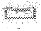
- a control device for a motor vehicle comprises a housing cover 1 and a bottom plate 2.
- the housing cover 1 and the bottom plate 2 form a cavity 3, in which a circuit carrier 4 is located.
- the circuit carrier 4 is glued on the inside of the housing cover 1 in particular with an electrically insulating thermal adhesive. If the housing cover 1 is made of a metallic material, for example, then the heat generated on the circuit substrate 4 is dissipated particularly well to the surroundings adjacent to the housing cover 1.
- At least one electronic component 5 and at least one electronic contact region 6 are arranged on the circuit carrier 4.
- a contact region 6 is in particular electrically connected via conductor tracks on the circuit carrier 4 to electronic components which are not located in the edge region of the circuit carrier 4.
- the housing cover 1 has an opening 9 in the region surrounding the circuit carrier 4, adjacent to an electronic component 5 and / or an electrical contact region 6.
- an opening 9 is on the outside of the housing cover 1, so the side facing away from the circuit board of the housing cover 1, a flexible film conductor 7, preferably formed as a foil conductor strips attached.
- an electrical contact region 11 is arranged at the end portion 10 of the film conductor strip 7, an electrical contact region 11 is arranged.
- the foil conductor strip 7 is placed over the opening 9 in such a way that it completely covers the opening 9 with its end section 10 and that the electrical contact area 11 is located completely in the opening 9, ie does not come into contact with the housing cover. Otherwise there would be a risk of a short circuit.
- the electrical contact region 11 on the film conductor 7 in the opening 9 is in turn electrically connected via the conductor tracks in the film conductor 7 in a manner not shown with electronic and / or electrical components, such as sensors or plugs outside the control unit.
- the cover plate 12 completely covers the opening 9 and causes the Foil strip 7 oil-tight with the housing cover 1 is connected.
- the coupling of the cover plate 12 to the housing cover 1 can be made by a non-positive or positive connection such as screwing or caulking.
- a breakthrough 9 circumferential ring seal 13 to ensure additional safety with respect to oil tightness.
- the seal 13 may be molded on the cover plate 12 for the sake of simplicity, but could also be fixed in a corresponding groove on the side facing the opening 9 of the cover plate 12.
- the film conductor strip 7 for example, by laminating, in particular cold lamination, fixed on the housing cover 1.
- the foil strip 7 it would also be conceivable for the foil strip 7 to be connected to the cover plate 12, for example by material bonding, such as by gluing or laminating. Then, the seal 13 would have to be mounted between the housing cover 1 and the film conductor strip 7.
- the housing cover 1 is coupled via a seal 16 oil-tight to the bottom plate 2.
- the bottom plate 2 has a cuboid depression 14. It would also be conceivable that the bottom plate 2 is formed as a flat plate and the housing cover 1 to form the cavity 3 hood-shaped. In order to arrive at a very compact gear unit, the bottom plate 2 of the control unit can be simultaneously part of the transmission hydraulic unit.
- Fig. 2 shows one too Fig. 1 alternative arrangement of the cover plate 12 on the housing cover 1.
- the housing cover 1 on its outer side in the region of the opening 9 surrounding the opening 9 surrounding, in its shape the shape of the cover plate corresponding recess 15.
- the Cover plate 12 is sunk in particular in the recess 15 that it is flush on its outer side with the outside of the housing cover 1.
- the film conductor strip 7 is as in Fig. 1 arranged directly on the housing cover 1 and covers the opening 9 completely.
- the seal 13 is located in the recess 15 between the film conductor strip 7 and the cover plate 12; but could also be arranged between the recess 15 and the film conductor strip 7.
- Fig. 3 shows a plan view of the inside of the housing cover 1 and serves mainly to illustrate the arrangement in the region of a breakthrough 9.
- the electrical contact portion 11 on the end portion 10 of the foil strip 7 is arranged in the opening 9, that he with the housing cover 1 is not in contact comes, so can cause a short circuit on the most metallic housing cover 1.
- the seal 13 runs around the aperture 9, either between the housing cover 1 and the foil conductor strip 7 or between the foil conductor strip 7 and the cover plate 12.
- the seal 13 runs entirely on the foil conductor strip 7, since a transition seal 13 on the housing plate 1 represents a potential leak would.
- the end portion 10 of the film conductor strip 7 thus covers both the opening 9 and the seal 13 entirely.
- the cover plate 12 in turn covers in this case the end portion 10 entirely.
- This arrangement is particularly useful when the seal 13 seals the transition from the cover plate 12 to the film conductor strip 7.
- the transition from the film conductor strip 7 to the housing cover 1 is sealed by the type of application of the film conductor strip 7 on the housing cover 1, that is, for example by lamination or gluing, on the other hand by the positive or non-positive connection of the cover plate 12 to the housing cover 1.
- the cover plate 12 extends entirely within the end portion 10 of the film conductor strip 7 to a transition from the film conductor strip 7 on the housing cover 1 and thus to avoid a potential leak.
- the End portion 10 depending on the dimensions of the cover plate, be wider than the rest of the film conductor strip. 7
- Fig. 4 shows a plan view of the outside of the housing cover. 1
Landscapes
- Engineering & Computer Science (AREA)
- Mechanical Engineering (AREA)
- Casings For Electric Apparatus (AREA)
- Control Of Transmission Device (AREA)
- General Details Of Gearings (AREA)
Abstract
Claims (11)
- Appareil de commande pour un véhicule automobile, qui comprend :a) une plaque de fond (2),b) un couvercle de carter (1) qui est raccordé à la plaque de fond (2) de façon étanche à l'huile et qui forme une cavité (3) avec la plaque de fond (2),c) un support de circuit (4) qui comprend au moins un composant (5) électronique et/ou au moins une zone de contact (6) électrique et qui est disposé à l'intérieur de la cavité (3) sur le côté intérieur du couvercle de carter (1),d) au moins un conducteur en lamelles (7) pour la connexion électrique d'au moins un composant (5) électronique et/ou d'au moins une zone de contact (6) électrique sur le support de circuit (4) avec des composants électroniques à l'extérieur de la cavité (3), ete) des lignes de connexion électriques (8) entre les composants (5) et/ou les zones de contact (6) sur le support de circuit (4) ou le conducteur en lamelles (7),
caractérisé en ce quef) dans la zone entourant de façon périphérique le support de circuit (4) à proximité d'un composant (5) électronique et/ou d'une zone de contact (6) électrique du support de circuit (4), le couvercle de carter (1) présente au moins une traversée (9),g) le conducteur en lamelles est exécuté au moins comme une bande de conducteur en lamelles (7) qui présente une zone de contact (11) électrique au moins à un tronçon d'extrémité (10) respectivement,h) sur ou dans la traversée (9), à partir du côté du couvercle de carter (1) qui est éloigné du support de circuit (4), il est respectivement disposé une bande de conducteur en lamelles (7) de sorte que le tronçon d'extrémité (10) de la bande de conducteur en lamelles (7) recouvre complètement la traversée (9),i) au-dessus ou dans la traversée (9), il est placé une plaque de couvercle (12) recouvrant complètement la traversée (9) de sorte que la bande de conducteur en lamelles (7) située au milieu est raccordée au couvercle de carter (2) de façon étanche à l'huile , etj) les lignes de connexion électriques (8) entre les composants (5) et/ou les zones de contact (6) sur le support de circuit (4) et la zone de contact (11) électrique sur le tronçon d'extrémité (10) de la bande de conducteur en lamelles (7) sont disposées dans la traversée (9) correspondante. - Appareil de commande selon la revendication 1, caractérisé en ce que le couvercle de carter (1) est en contact direct avec un fluide environnant et est constitué en tant que puits de chaleur pour la chaleur produite par les composants (5) électroniques sur le support de circuit (4).
- Appareil de commande selon la revendication 1 ou 2, caractérisé en ce que la bande de conducteur en lamelles (7) est raccordée au couvercle de carter (1), au moins dans la zone de la traversée (9), ou à la plaque de couvercle (12) au moyen d'une liaison par adhérence telle que l'encollage ou le plastifiage.
- Appareil de commande selon une des revendications précédentes, caractérisé en ce que, entre le couvercle de carter (1) et la bande de conducteur en lamelles (7) ou entre la bande de conducteur en lamelles (7) et la plaque de couvercle (12), il est disposé un joint d'étanchéité (13) périphérique autour de la traversée (9).
- Appareil de commande selon la revendication 4, caractérisé en ce que le joint d'étanchéité (13) périphérique autour de la traversée (9) est disposé à l'intérieur de la bande de conducteur en lamelles (7), entourant la zone de contact (11) électrique sur la bande de conducteur en lamelles (7).
- Appareil de commande selon une des revendications précédentes, caractérisé en ce que le couvercle de carter (1) présente, dans la zone de la traversée (9), un creux (15) en forme de gradin destiné à loger la plaque de couvercle (12) et entourant de façon périphérique la traversée (9).
- Appareil de commande selon une des revendications précédentes, caractérisé en ce que la plaque de fond (2) présente un creux (14) pour la formation de la cavité (3) avec le couvercle de carter (1).
- Appareil de commande selon une des revendications précédentes, caractérisé en ce que la plaque de couvercle (12) est raccordée au couvercle de carter (1) au moyen d'une liaison de force ou d'une liaison de forme comme le vissage ou le matage.
- Appareil de commande selon une des revendications précédentes, caractérisé en ce que la plaque de fond (2) fait partie d'une unité hydraulique d'engrenage.
- Procédé de fabrication d'un appareil de commande pour un véhicule automobile selon la revendication 1, caractérisé par les étapes:a) fourniture d'un couvercle de carter (1),b) mise en place d'un support de circuit (4) sur le côté intérieur du couvercle de carter (1), le support de circuit (4) comprenant au moins un composant (5) électronique et/ou au moins une zone de contact (6) électrique, et le couvercle de carter (1) présentant au moins une traversée (9) dans la zone entourant de façon périphérique le support de circuit (4) à proximité d'un composant (5) électronique et/ou d'une zone de contact (6) électrique,c) positionnement et fixation d'au moins un conducteur en lamelles (7) en forme de bande sur le côté du couvercle de carter (1) éloigné du support de circuit (4) de sorte qu'un tronçon d'extrémité (10) de la bande de conducteur en lamelles (7) recouvre complètement la traversée (9) et qu'une zone de contact (11) électrique est entièrement disposée sur le tronçon d'extrémité (10) de la bande de conducteur en lamelles (7) dans la traversée (9) respective,d) mise en place d'une plaque de couvercle (12) sur la traversée (9) de sorte que la bande de conducteur en lamelles (7) située au milieu est raccordée au couvercle de carter (1) de façon étanche à l'huile,e) mise en place de lignes de connexion électriques (8) entre les composants (5) électroniques et/ou les zones de contact (6) sur le support de circuit (4) et la zone de contact (11) électrique sur le tronçon d'extrémité (10) de la bande de conducteur en lamelles (7) dans la traversée (9) correspondante, etf) montage étanche à l'huile du couvercle de carter (1) sur la plaque de fond (2), une cavité (3) étant formée pour recevoir le support de circuit (4).
- Procédé selon la revendication 10, caractérisé en ce que le support de circuit (4) et/ou la bande de conducteur en lamelles (7) au moins au nombre de un est mis/mise en place sur le couvercle de carter (1) ou la plaque de couvercle (12) au moyen de collage ou de plastifiage, en particulier de plastifiage à froid.
Applications Claiming Priority (2)
| Application Number | Priority Date | Filing Date | Title |
|---|---|---|---|
| DE102006049592A DE102006049592A1 (de) | 2006-10-20 | 2006-10-20 | Steuergerät für ein Kraftfahrzeug |
| PCT/DE2007/001837 WO2008046401A1 (fr) | 2006-10-20 | 2007-10-16 | Appareil de commande pour véhicule automobile |
Publications (2)
| Publication Number | Publication Date |
|---|---|
| EP2055155A1 EP2055155A1 (fr) | 2009-05-06 |
| EP2055155B1 true EP2055155B1 (fr) | 2011-01-12 |
Family
ID=38962747
Family Applications (1)
| Application Number | Title | Priority Date | Filing Date |
|---|---|---|---|
| EP07817672A Active EP2055155B1 (fr) | 2006-10-20 | 2007-10-16 | Appareil de commande pour vehicule automobile |
Country Status (5)
| Country | Link |
|---|---|
| US (1) | US8059407B2 (fr) |
| EP (1) | EP2055155B1 (fr) |
| JP (1) | JP5294175B2 (fr) |
| DE (3) | DE102006049592A1 (fr) |
| WO (1) | WO2008046401A1 (fr) |
Families Citing this family (8)
| Publication number | Priority date | Publication date | Assignee | Title |
|---|---|---|---|---|
| DE102006049593A1 (de) * | 2006-10-20 | 2008-04-24 | Conti Temic Microelectronic Gmbh | Kompaktes Steuergerät für ein Kraftfahrzeug |
| DE102010062653A1 (de) * | 2010-12-08 | 2012-06-14 | Robert Bosch Gmbh | Steuermodul und Verfahren zu seiner Herstellung |
| DE102011056742B4 (de) * | 2011-05-09 | 2019-07-18 | Conti Temic Microelectronic Gmbh | Steuergerät mit einer Getterschicht in einem Kraftfahrzeug |
| US9651142B2 (en) * | 2013-03-11 | 2017-05-16 | Dana Automotive Systems Group, Llc | Differential carrier temperature sensing method |
| DE102013215149A1 (de) | 2013-08-01 | 2015-02-19 | Conti Temic Microelectronic Gmbh | Mehrstufiges Dichtsystem zum Einsatz in einem Kraftfahrzeugsteuergerät |
| JP6076872B2 (ja) * | 2013-09-19 | 2017-02-08 | 日立オートモティブシステムズ株式会社 | 電子制御装置 |
| DE102013224119B4 (de) * | 2013-11-26 | 2022-11-10 | Vitesco Technologies Germany Gmbh | Anordnung zum elektrischen Verbinden eines Schaltungsträgers |
| TWM519879U (zh) * | 2015-08-03 | 2016-04-01 | 道登電子材料股份有限公司 | 電子裝置之改良散熱結構 |
Family Cites Families (28)
| Publication number | Priority date | Publication date | Assignee | Title |
|---|---|---|---|---|
| DE3913066A1 (de) | 1989-04-21 | 1990-11-08 | Schoppe & Faeser Gmbh | Verfahren zur herstellung eines hermetisch dichten gehaeuses sowie nach diesem verfahren hergestelltes gehaeuse |
| DE4023319C1 (fr) | 1990-07-21 | 1991-12-12 | Robert Bosch Gmbh, 7000 Stuttgart, De | |
| DE4102265A1 (de) | 1991-01-26 | 1992-07-30 | Telefunken Electronic Gmbh | Gehaeuse kfz-elektronik |
| US5586388A (en) | 1991-05-31 | 1996-12-24 | Nippondenso Co., Ltd. | Method for producing multi-board electronic device |
| US5831836A (en) * | 1992-01-30 | 1998-11-03 | Lsi Logic | Power plane for semiconductor device |
| DE4228818C2 (de) | 1992-08-29 | 2003-04-03 | Bosch Gmbh Robert | Elektrisches Gerät, insbesondere Schalt- und Steuergerät für Kraftfahrzeuge, und Verfahren zur Herstellung |
| DE4340280C2 (de) | 1993-09-13 | 1996-08-29 | Duerrwaechter E Dr Doduco | Bauteilesatz für ein Gehäuse aus Kunststoff zum Aufnehmen von elektrischen Bauelementen |
| DE29508661U1 (de) | 1995-05-24 | 1996-09-26 | Robert Bosch Gmbh, 70469 Stuttgart | Elektrische Verbindung von einander örtlich getrennten Bauteilen |
| DE19712842C1 (de) | 1997-03-26 | 1998-08-13 | Siemens Ag | Steuergerät für ein Kraftfahrzeug |
| DE19720167B4 (de) * | 1997-05-14 | 2006-06-22 | Siemens Ag | Struktur zum Anschließen einer Mehrzahl voneinander entfernter elektrischer Bauelemente an eine Zentraleinheit |
| US5949137A (en) | 1997-09-26 | 1999-09-07 | Lsi Logic Corporation | Stiffener ring and heat spreader for use with flip chip packaging assemblies |
| DE19907949C2 (de) | 1999-02-24 | 2002-11-07 | Siemens Ag | Steuergerät für ein Kraftfahrzeug |
| DE19955603C1 (de) * | 1999-11-18 | 2001-02-15 | Siemens Ag | Steuergerät für ein Kraftfahrzeug und Herstellungsverfahren |
| DE10036138C1 (de) | 2000-07-25 | 2002-01-24 | Siemens Ag | Baugruppe mit Gehäusestecker |
| DE10116796B4 (de) * | 2001-04-04 | 2013-05-16 | Continental Automotive Gmbh | Elektronisch-hydraulisches Getriebesteuermodul |
| JP2003092476A (ja) * | 2001-09-18 | 2003-03-28 | Hitachi Unisia Automotive Ltd | 電子部品装置 |
| JP2003112532A (ja) * | 2001-10-05 | 2003-04-15 | Aisin Aw Co Ltd | 電子制御装置を備えた自動変速機 |
| DE10315438A1 (de) * | 2003-04-03 | 2004-10-14 | Conti Temic Microelectronic Gmbh | Anordnung von elektrischen und/oder mechanischen Komponenten auf einer großen, flexiblen Folienleiterfläche |
| DE10315432A1 (de) * | 2003-04-03 | 2004-10-14 | Conti Temic Microelectronic Gmbh | Anordnung zum elektrischen Verbinden |
| DE10327476A1 (de) * | 2003-06-18 | 2005-01-05 | Conti Temic Microelectronic Gmbh | Drucksensor-Anordnung |
| DE10340974A1 (de) | 2003-09-05 | 2005-03-24 | Robert Bosch Gmbh | Steuergeräteeinheit und Verfahren zur Hestellung derselben |
| DE102004061818A1 (de) * | 2004-12-22 | 2006-07-06 | Robert Bosch Gmbh | Steuermodul |
| DE102005002813B4 (de) | 2005-01-20 | 2006-10-19 | Robert Bosch Gmbh | Steuermodul |
| WO2006108392A1 (fr) * | 2005-04-15 | 2006-10-19 | Conti Temic Microelectronic Gmbh | Appareil de commande |
| DE102005046826A1 (de) * | 2005-09-29 | 2007-04-05 | Robert Bosch Gmbh | Steuergerät, insbesondere für ein Kraftfahrzeuggetriebe |
| DE102006049593A1 (de) | 2006-10-20 | 2008-04-24 | Conti Temic Microelectronic Gmbh | Kompaktes Steuergerät für ein Kraftfahrzeug |
| JPWO2008062865A1 (ja) * | 2006-11-24 | 2010-03-04 | アイシン・エィ・ダブリュ株式会社 | 自動変速機のコントロールユニット及びそのコントロールユニットを搭載した自動変速機 |
| DE102008014457A1 (de) * | 2007-03-20 | 2008-09-25 | Conti Temic Microelectronic Gmbh | Schnittstelle |
-
2006
- 2006-10-20 DE DE102006049592A patent/DE102006049592A1/de not_active Withdrawn
-
2007
- 2007-10-16 EP EP07817672A patent/EP2055155B1/fr active Active
- 2007-10-16 DE DE502007006258T patent/DE502007006258D1/de active Active
- 2007-10-16 US US12/311,991 patent/US8059407B2/en active Active
- 2007-10-16 JP JP2009534981A patent/JP5294175B2/ja not_active Expired - Fee Related
- 2007-10-16 DE DE112007002191T patent/DE112007002191A5/de not_active Withdrawn
- 2007-10-16 WO PCT/DE2007/001837 patent/WO2008046401A1/fr not_active Ceased
Also Published As
| Publication number | Publication date |
|---|---|
| WO2008046401A1 (fr) | 2008-04-24 |
| US8059407B2 (en) | 2011-11-15 |
| US20100020495A1 (en) | 2010-01-28 |
| DE112007002191A5 (de) | 2009-06-18 |
| JP5294175B2 (ja) | 2013-09-18 |
| JP2010507533A (ja) | 2010-03-11 |
| DE102006049592A1 (de) | 2008-04-30 |
| DE502007006258D1 (de) | 2011-02-24 |
| EP2055155A1 (fr) | 2009-05-06 |
Similar Documents
| Publication | Publication Date | Title |
|---|---|---|
| EP2055155B1 (fr) | Appareil de commande pour vehicule automobile | |
| EP2087779B1 (fr) | Appareil de commande compact pour véhicule automobile | |
| EP1831055B1 (fr) | Module de commande | |
| EP2163148B2 (fr) | Unité de commande électrique | |
| DE19907949C2 (de) | Steuergerät für ein Kraftfahrzeug | |
| EP3381246A1 (fr) | Module électronique et procédé de fabrication d'un module électronique avec un boîtier étanche aux fluides | |
| DE10101091A1 (de) | Hydraulisches Kraftfahrzeug-Getriebesteuergerät mit Kunststoff-Hydraulikverteilerplatte und darin integrierten Leitern und Verfahren zu dessen Herstellung | |
| EP2107604A2 (fr) | Module semi-conducteur de puissance doté d'un circuit étanche hermétique et son procédé de fabrication | |
| DE102013215227A1 (de) | Verkapseltes Elektronikmodul mit Flexfolienanbindung, insbesondere für ein Kfz-Getriebesteuermodul | |
| EP3292593B1 (fr) | Dispositif de connexion électrique | |
| EP2586059A1 (fr) | Module de commande encapsulé pour un véhicule à moteur | |
| EP2033269B1 (fr) | Boîtier électronique comprenant une interface standard | |
| DE102010002945A1 (de) | Schaltungsanordnung und zugehöriges steuergerät für ein kraftfahrzeug | |
| WO2016177629A1 (fr) | Composant électronique et son procédé de fabrication | |
| DE102007039618B4 (de) | Modul für eine integrierte Steuerelektronik mit vereinfachtem Aufbau | |
| EP2883431A1 (fr) | Module de commande de boîte de vitesses d'une boîte de vitesses de véhicule automobile à construction en sandwich, comportant des éléments de construction disposés de façon étanche | |
| DE102007012182B4 (de) | Steuergerät für ein Kraftfahrzeug | |
| DE102016215410B4 (de) | Elektronische Schaltungsbaugruppe | |
| DE102015219076A1 (de) | Elektronikmodulanordnung für ein Getriebesteuermodul und Getriebesteuermodul | |
| DE102011088978A1 (de) | Elektronikmodul für ein Fahrzeug | |
| DE102013224119B4 (de) | Anordnung zum elektrischen Verbinden eines Schaltungsträgers | |
| DE102013217363A1 (de) | Neuartige Anbindung einer flexiblen Leiterplatte an ein Steuergerätegehäuse | |
| WO2018019499A1 (fr) | Ensemble carte de circuit imprimé | |
| DE102007020016A1 (de) | Flexibler Leiterbahnträger und Leiterbahnträgervorrichtung | |
| DE102015212092A1 (de) | Elektronische Komponente und Verfahren zu deren Herstellung |
Legal Events
| Date | Code | Title | Description |
|---|---|---|---|
| PUAI | Public reference made under article 153(3) epc to a published international application that has entered the european phase |
Free format text: ORIGINAL CODE: 0009012 |
|
| 17P | Request for examination filed |
Effective date: 20090317 |
|
| AK | Designated contracting states |
Kind code of ref document: A1 Designated state(s): AT BE BG CH CY CZ DE DK EE ES FI FR GB GR HU IE IS IT LI LT LU LV MC MT NL PL PT RO SE SI SK TR |
|
| AX | Request for extension of the european patent |
Extension state: AL BA HR MK RS |
|
| RIN1 | Information on inventor provided before grant (corrected) |
Inventor name: WENK, ALEXANDER Inventor name: GRAMANN, MATTHIAS Inventor name: HENNIGER, JUERGEN Inventor name: EGLINGER, MARKUS |
|
| DAX | Request for extension of the european patent (deleted) | ||
| GRAP | Despatch of communication of intention to grant a patent |
Free format text: ORIGINAL CODE: EPIDOSNIGR1 |
|
| GRAS | Grant fee paid |
Free format text: ORIGINAL CODE: EPIDOSNIGR3 |
|
| GRAA | (expected) grant |
Free format text: ORIGINAL CODE: 0009210 |
|
| AK | Designated contracting states |
Kind code of ref document: B1 Designated state(s): DE FR |
|
| REF | Corresponds to: |
Ref document number: 502007006258 Country of ref document: DE Date of ref document: 20110224 Kind code of ref document: P |
|
| REG | Reference to a national code |
Ref country code: DE Ref legal event code: R096 Ref document number: 502007006258 Country of ref document: DE Effective date: 20110224 |
|
| PLBE | No opposition filed within time limit |
Free format text: ORIGINAL CODE: 0009261 |
|
| STAA | Information on the status of an ep patent application or granted ep patent |
Free format text: STATUS: NO OPPOSITION FILED WITHIN TIME LIMIT |
|
| 26N | No opposition filed |
Effective date: 20111013 |
|
| REG | Reference to a national code |
Ref country code: DE Ref legal event code: R097 Ref document number: 502007006258 Country of ref document: DE Effective date: 20111013 |
|
| REG | Reference to a national code |
Ref country code: FR Ref legal event code: PLFP Year of fee payment: 9 |
|
| REG | Reference to a national code |
Ref country code: FR Ref legal event code: PLFP Year of fee payment: 10 |
|
| REG | Reference to a national code |
Ref country code: FR Ref legal event code: PLFP Year of fee payment: 11 |
|
| REG | Reference to a national code |
Ref country code: FR Ref legal event code: PLFP Year of fee payment: 12 |
|
| REG | Reference to a national code |
Ref country code: DE Ref legal event code: R084 Ref document number: 502007006258 Country of ref document: DE |
|
| REG | Reference to a national code |
Ref country code: DE Ref legal event code: R081 Ref document number: 502007006258 Country of ref document: DE Owner name: VITESCO TECHNOLOGIES GERMANY GMBH, DE Free format text: FORMER OWNER: CONTI TEMIC MICROELECTRONIC GMBH, 90411 NUERNBERG, DE |
|
| REG | Reference to a national code |
Ref country code: DE Ref legal event code: R081 Ref document number: 502007006258 Country of ref document: DE Owner name: VITESCO TECHNOLOGIES GERMANY GMBH, DE Free format text: FORMER OWNER: VITESCO TECHNOLOGIES GERMANY GMBH, 30165 HANNOVER, DE |
|
| P01 | Opt-out of the competence of the unified patent court (upc) registered |
Effective date: 20230530 |
|
| PGFP | Annual fee paid to national office [announced via postgrant information from national office to epo] |
Ref country code: DE Payment date: 20231031 Year of fee payment: 17 |
|
| PGFP | Annual fee paid to national office [announced via postgrant information from national office to epo] |
Ref country code: FR Payment date: 20241021 Year of fee payment: 18 |
|
| REG | Reference to a national code |
Ref country code: DE Ref legal event code: R119 Ref document number: 502007006258 Country of ref document: DE |
|
| PG25 | Lapsed in a contracting state [announced via postgrant information from national office to epo] |
Ref country code: DE Free format text: LAPSE BECAUSE OF NON-PAYMENT OF DUE FEES Effective date: 20250501 |