EP2055169B1 - Klappsystem für ein gezogenes landwirtschaftliches Gerät - Google Patents
Klappsystem für ein gezogenes landwirtschaftliches Gerät Download PDFInfo
- Publication number
- EP2055169B1 EP2055169B1 EP08153208.7A EP08153208A EP2055169B1 EP 2055169 B1 EP2055169 B1 EP 2055169B1 EP 08153208 A EP08153208 A EP 08153208A EP 2055169 B1 EP2055169 B1 EP 2055169B1
- Authority
- EP
- European Patent Office
- Prior art keywords
- implement
- longitudinal axis
- header
- rotation
- arms
- Prior art date
- Legal status (The legal status is an assumption and is not a legal conclusion. Google has not performed a legal analysis and makes no representation as to the accuracy of the status listed.)
- Ceased
Links
Images




Classifications
-
- A—HUMAN NECESSITIES
- A01—AGRICULTURE; FORESTRY; ANIMAL HUSBANDRY; HUNTING; TRAPPING; FISHING
- A01D—HARVESTING; MOWING
- A01D34/00—Mowers; Mowing apparatus of harvesters
- A01D34/01—Mowers; Mowing apparatus of harvesters characterised by features relating to the type of cutting apparatus
- A01D34/412—Mowers; Mowing apparatus of harvesters characterised by features relating to the type of cutting apparatus having rotating cutters
- A01D34/63—Mowers; Mowing apparatus of harvesters characterised by features relating to the type of cutting apparatus having rotating cutters having cutters rotating about a vertical axis
- A01D34/64—Mowers; Mowing apparatus of harvesters characterised by features relating to the type of cutting apparatus having rotating cutters having cutters rotating about a vertical axis mounted on a vehicle, e.g. a tractor, or drawn by an animal or a vehicle
- A01D34/66—Mowers; Mowing apparatus of harvesters characterised by features relating to the type of cutting apparatus having rotating cutters having cutters rotating about a vertical axis mounted on a vehicle, e.g. a tractor, or drawn by an animal or a vehicle with two or more cutters
- A01D34/661—Mounting means
-
- A—HUMAN NECESSITIES
- A01—AGRICULTURE; FORESTRY; ANIMAL HUSBANDRY; HUNTING; TRAPPING; FISHING
- A01B—SOIL WORKING IN AGRICULTURE OR FORESTRY; PARTS, DETAILS, OR ACCESSORIES OF AGRICULTURAL MACHINES OR IMPLEMENTS, IN GENERAL
- A01B73/00—Means or arrangements to facilitate transportation of agricultural machines or implements, e.g. folding frames to reduce overall width
- A01B73/02—Folding frames
- A01B73/06—Folding frames foldable about a vertical axis
- A01B73/065—Folding frames foldable about a vertical axis to a position essentially forward of the axis, in relation to the direction of travel
Definitions
- the present invention relates generally to an agricultural implement.
- Some towable agricultural implements require that the implement be towed off to one side of the tractor when in operation - possibly with the ability to be towed on either side - and directly behind the tractor for transport.
- the towing at these various locations is effected by angling the implement tongue relative to an implement longitudinal axis, while maintaining an orientation of an implement frame with respect to that longitudinal axis.
- the need for this flexibility presents difficulties in providing shaft power smoothly to the implement regardless of the tongue angle.
- Universal joints are relatively inexpensive and permit changes of drive direction, but reduce energy transfer efficiency, are unable to accommodate great angles, and produce oscillating power transfer when at and angle. Furthermore, universal joints require regular maintenance and eventual replacement.
- DE 4407812 A1 discloses a towable mowing device comprising a longitudinal axis parallel to the usual direction of travel.
- the mowing device comprises mowing tools bars supported by two pivotable support arms mounted on a frame at opposite sides of the longitudinal axis.
- the support arms are pivotable about a respective vertical axis of rotation with respect to the frame.
- the vertical axes of rotation are arranged on a single line perpendicular to the longitudinal axis of the mowing machine.
- DE 43 14 250 C1 discloses a supporting frame for a rotary mower.
- the rotary mower is a towable mowing device.
- the rotary mower comprises a longitudinal axis parallel to the usual direction of travel.
- the mowing device comprises two cutter bars arranged perpendicular to the longitudinal axis of the mowing device. Each cutting bar is supported by two arms, an outer arm and a central arm.
- the outer arm for each cutter bar is arranged at opposite sides of the longitudinal axis. Opposite ends of the central arm each support one of the two cutter bars.
- the outer arms and central arm are pivotable about a respective vertical axis of rotation.
- the vertical axes of rotation are arranged on a single line perpendicular to the longitudinal axis of the mowing machine.
- the two arms supporting a cutting bar form a parallelogram linkage mechanism so that the cutterbars can be moved by a pivoting movement of the arms between a transport position and an operative position.
- the cutter bars are arranged perpendicular to the longitudinal axis of the device.
- the present invention relates to an implement as claimed in claim 1. Further embodiments of the invention are described in the dependent claims.
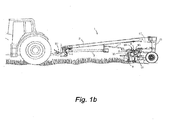
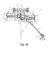
- the present invention comprises a suspension system for an agricultural mower 1, shown in its entirety in Figs. 1a-2c , and 5.
- the present invention relates to a drive system capable of transmitting rotation from a Power Takeoff (PTO) shaft of a towing tractor to the cutters of an agricultural mower having multiple frames able to pivot and rotate as described in U.S. Patent Application No. 11/927,866, filed October 30, 2007 and the co-pending European application filed under our Ref. 69310.
- the multi-frame mower 1 having the aforementioned motions enables the cutter bars 9 to float on the ground. Float provides the ability to engage the ground surface such that a consistent cut height is achieved. This desirable quality held by such a mower 1 requires the driveshaft configuration of the present invention.
- a two-point arm structure 3 is used to connect the mower tongue 2 to the two lower links of a 3-point tractor linkage (not shown) properly positioning the mower 1 such that the PTO shaft from the tractor can be connected to the tongue gearbox system 4 via an implement driveline 37 comprising a universal joint.
- the two-point arm 3, as particularly illustrated in Fig. 3 is connected to the tractor links by cylindrical pins 75 which pass through spherical bearings, or ball joints, in the tractor links to allow for ground slope variations in the direction of travel as well as relative roll angle between the tongue 2 and the tractor.
- the usual direction of travel is hereby defined as the direction the agricultural mower 1 is drawn during mowing.
- said usual direction of travel is to the left.
- FIG. 5 An alternative embodiment of the hitch system is shown in Fig. 5 .
- the tongue 2 is attached to a tractor drawbar by a pin-type hitch 67, thereby properly positioning the mower 1 to permit the tractor PTO shaft to be connected to a tongue jack-shaft (not shown) via an implement driveline 37 comprising a universal joint.
- the main shaft 5 connects to the jack shaft at the front of the tongue 2.
- the tongue gearbox system 4 is comprised of an upper gearbox 24 and a lower gearbox 25, shown in Fig. 3 , which each alter the axis of rotation of the driveshaft by 90° and also can provide gear reduction.
- the two gearboxes 24, 25 are pivotally connected with a common shaft defining a vertical axis of rotation 70.
- This assembly is a swiveling gearbox assembly 4 which allows the upper gearbox 24 to be rigidly mounted to the tongue while allowing the lower gearbox 25 to rotate freely about the vertical axis of rotation 70.
- the tractor may be positioned by angling the tongue to various angles relative to the longitudinal axis 52 of the agricultural mower 1.
- the output shaft of the upper sub-frame gearbox 35 is also the input shaft of the lower sub-frame gearbox 36, making these two gearboxes 35, 36 a swiveling pair, referred to here as the "sub-frame gearbox system" 18, as described for the tongue gearbox system 4.
- the lower sub-frame gearbox 36 is rigidly mounted to the sub-frame 10 while the upper sub-frame gearbox 35 rotates freely to stay generally aligned with the tongue 2, via a steering link or steering bar 7.
- a benefit of the secondary shaft 23 is that the secondary shaft 23 may be oriented at a variable angle with the tongue 2 such that the sub-frame 10 can be raised or lowered relative to the tongue 2 and main frame 15.
- the secondary shaft 23 is connected to the sub-frame gearbox system 18 via a universal joint or a constant velocity joint and through a friction clutch which is in-line such that under excessive torque it will disengage the drive system, as is well understood by those of ordinary skill in the art.
- the swiveling sub-frame gearbox system 18 permits the driveshaft 5, 23 to perform its function even when the tongue 2 is not orthogonal to the sub-frame 10. Clearly, such is allowed by the pivotal mounting of the tongue to the main frame 15, controlled by a swing cylinder 17.
- a steering bar 7 extends between the sub-frame gearbox system 18 and the tongue strut, and is connected such that the sub-frame 10 is allowed to lift and lower.
- the upper gearbox 35 alters the axis of rotation of the shaft by 90° into the lower gearbox 36 which changes the rotation angle by 90° again and transmits the rotation into shafts extending out to the headers 6 via universal joints.
- the arms 8 are pivotally connected to the sub-frame 10 such that they may rotate about a vertical axis of rotation between a transport position ( Figs. 1a , 2a , and 5 ) and a mowing position ( Figs. 1b , 2b , and 2c ).
- the arms 8 In the transport position, the arms 8 rotate to a position such that the cutter bars 9 are substantially parallel to the longitudinal axis 52.
- the arms In the mowing position, the arms rotate to a position such that the cutter bars 9 are substantially perpendicular to the longitudinal axis 52, and are slightly offset relative to one another.
- the ability to fold in the arms 8 for transport enables a wide-cut agricultural mower 1 to be narrowed sufficiently for legal transport on U.S. roadways. Additionally, because the cutter bars 9 fold within a horizontal plane, the center of mass of the agricultural mower 1 remains low, enhancing stability.
- Folding is effected by a folding cylinder 85. Because the folding of the cutter bars 9 does not entail lifting the cutter bars 9, folding may alternatively be performed manually. Folding the cutter bars 9 on a vertical pivot axis on which the arms 8 pivot to the transport position, makes the agricultural mower 1 very stable when compared with the alternative of folding on a horizontal pivot axis. Offsetting the arms 8 and slightly overlapping them in the transverse direction allows the cutter bars 9 to rotate independently, while not missing any crop or being in danger of having their blades impact each other. With the cutterbars 9 offset, the mower is better able to follow the ground contour.
- the arm shafts 20 are connected to the lower sub-frame gearbox 36 via universal joints which allow the arms 8 to rotate inward for transport or outward for mowing. In the transport position the universal joints are not intended to allow rotation of the arm shafts 20.
- Each arm 8 pivotally supports a header 6 with a cylindrical bearing 38 as shown in Fig 4 . This allows rotation of the header 6 with an axis of rotation perpendicular to that header 6, which in the mowing position allows the cutter bars 9 to follow the terrain.
- the header 6 supports a cutter bar 9 on its outer end by a vertical support structure 26 which is rigidly connected to the header 6.
- the header 6 further includes a 90° gearbox 21 located at the outer end of the header 6.
- This entire assembly has a center of gravity approximately located at the pivot point 38, such that the cutter bar 9 will remain level when the header 6 is suspended by the arm 8.
- the 90° gearbox 21 of each header 6 accepts the arm shafts 20 through universal or CV joints to transmit the rotation through vertical shafts 27 leading to the cutter bars 9.
- the universal or CV joints allow for the pivoting of the header 6 with respect to the arm 8.
- the cutter bars 9 themselves are supported from above only at their outer ends by the vertical support structure 26, such that the cutter bars 9 arc cantilevered from that point inward.
- the drive shaft to the cutter bar 27 is aligned with this vertical support structure 26, such that the cutter bar supporting structure and drive are in the same space, minimizing disruption to the flow of cut material.
- a first disk 16a is mounted atop the cutter bar 9.
- This first disk 16a is specifically designed for accepting the driveshaft 27 from above via a universal joint.
- the driveshaft 27 is protected by a drum which throws cut material to the side of the driveshaft and discourages wrapping on the shaft as it extends downward from the header 6.
- the first disk 16a as well as subsequent disks 16 spaced along the cutter bar 9 self-contain small 90° gearboxes.
- a hexagonal shaft connects the row of cutter disks 16a, 16 and rotates with an axis of rotation substantially parallel to the arm 8. Blades mounted to the cutter disks 16a, 16 are rotated about the vertical axis of each disk 16a, 16 to cut the crop.
- novel drive system herein described may be utilized for any implement making use of a floating work tool.
- the invention is not intended to be limited to agricultural mowers.
Landscapes
- Life Sciences & Earth Sciences (AREA)
- Environmental Sciences (AREA)
- Engineering & Computer Science (AREA)
- Mechanical Engineering (AREA)
- Soil Sciences (AREA)
- Agricultural Machines (AREA)
- Harvester Elements (AREA)
Claims (8)
- Schleppbare landwirtschaftliche Vorrichtung (1), wobei die landwirtschaftliche Vorrichtung (1) umfasst:- einen Hauptrahmen (15),- einen Unterrahmen (10), welcher in Bezug auf den Hauptrahmen (15) gelenkig ist,- eine Zugdeichsel (2), welche bei Betätigung derart verschwenkbar an dem Hauptrahmen (15) angebracht ist, dass die Zugdeichsel (2) in verschiedenen Winkeln relativ zu dem Hauptrahmen (15) und relativ zu einer normalen Fahrtrichtung angeordnet sein kann, wobei die Vorrichtung (1) eine Längsachse (52) parallel zur normalen Fahrtrichtung umfasst,- erste und zweite Arme (8), die um eine entsprechende vertikale Drehachse zwischen einer Transportposition und einer Arbeitsposition verschwenkbar mit dem Unterrahmen (10) verbunden sind, wobei sich die Arme (8) auf gegenüberliegenden Seiten der Längsachse (52) erstrecken, so dass die Vorrichtung zum Betrieb und zum Transport klappbar ist, und wobei die Arme (8) jeweils Arbeitswerkzeuge (9), insbesondere Messerbalken, tragen, so dass die Arbeitswerkzeuge (9) in eine horizontale Ebene klappbar sind, wobei die Arbeitswerkzeuge (9) eine Längsachse aufweisen,dadurch gekennzeichnet, dass die entsprechenden vertikalen Drehachsen der ersten und zweiten Arme (8) in Bezug zueinander versetzt in Längsrichtung angeordnet sind, welche durch die Längsachse (52) definiert wird, und die Längsachsen der Arbeitswerkzeuge (9) in der Transportposition im Wesentlichen parallel zur Längsachse (52) der Vorrichtung angeordnet sind, und die Längsachsen der Arbeitswerkzeuge (9) in der Arbeitsposition im Wesentlichen senkrecht zur Längsachse (52) der Vorrichtung und relativ zueinander leicht versetzt angeordnet sind.
- Vorrichtung (1) nach Anspruch 1,
wobei die Arme (8) unterschiedlich lang sind. - Vorrichtung (1) nach Anspruch 1 oder 2,
wobei jeder Arm (8) ein Kopfstück (6) verschwenkbar um eine Drehachse (38) abstützt, welche im Wesentlichen senkrecht zu dem Kopfstück (6) angeordnet ist. - Vorrichtung (1) nach Anspruch 3,
wobei die Drehachse durch ein zylindrisches Lager (38) gebildet ist. - Vorrichtung (1) nach einem der Ansprüche 3 oder 4,
wobei jedes Kopfstück (6) ein Arbeitswerkzeug, insbesondere einen Messerbalken (9), abstützt. - Vorrichtung (1) nach Anspruch 5,
wobei jedes Kopfstück (6) ein Getriebe (21) umfasst, das an einem äußeren Ende des Kopfstücks (6) angeordnet ist. - Vorrichtung nach Anspruch 6,
wobei die Anordnung, umfassend das Kopfstück (6), das Arbeitswerkzeug (9) und das Getriebe (21), einen Schwerpunkt aufweist, der sich in etwa auf der Drehachse (38) befindet. - Vorrichtung nach einem der Ansprüche 1 bis 7,
wobei es sich bei den Arbeitswerkzeugen (9) um Messerbalken handelt, und wobei die Messerbalken in der Transportposition im Wesentlichen parallel zur Längsachse (52) angeordnet sind, und wobei die Messerbalken in der Arbeitsposition im Wesentlichen senkrecht zur Längsachse (52) und relativ zueinander leicht versetzt angeordnet sind.
Applications Claiming Priority (1)
| Application Number | Priority Date | Filing Date | Title |
|---|---|---|---|
| US11/928,082 US7658056B2 (en) | 2007-10-30 | 2007-10-30 | System for folding an agricultural machine with a floating work tool |
Publications (3)
| Publication Number | Publication Date |
|---|---|
| EP2055169A2 EP2055169A2 (de) | 2009-05-06 |
| EP2055169A3 EP2055169A3 (de) | 2009-10-21 |
| EP2055169B1 true EP2055169B1 (de) | 2014-06-18 |
Family
ID=40297666
Family Applications (1)
| Application Number | Title | Priority Date | Filing Date |
|---|---|---|---|
| EP08153208.7A Ceased EP2055169B1 (de) | 2007-10-30 | 2008-03-25 | Klappsystem für ein gezogenes landwirtschaftliches Gerät |
Country Status (2)
| Country | Link |
|---|---|
| US (3) | US7658056B2 (de) |
| EP (1) | EP2055169B1 (de) |
Families Citing this family (18)
| Publication number | Priority date | Publication date | Assignee | Title |
|---|---|---|---|---|
| HU229564B1 (en) * | 2007-01-26 | 2014-02-28 | Optigep Kft | Harvest adapter equipped with stalk crusher for cereals, mainly for sunflower |
| US7726109B2 (en) | 2007-10-30 | 2010-06-01 | Vermeer Manufacturing Co. | Four-bar linkage for suspending a header for an agricultural implement |
| AU2009261926B2 (en) * | 2008-06-27 | 2013-01-31 | The Toro Company | Reel mower |
| NL1037078C2 (nl) * | 2009-06-26 | 2010-12-28 | Lely Patent Nv | Landbouwmachine. |
| US8261521B2 (en) * | 2009-08-31 | 2012-09-11 | Vermeer Manufacturing Company | Self-leveling four-bar linkage for suspending a header of an agricultural implement |
| US8056307B2 (en) * | 2009-10-05 | 2011-11-15 | Cnh America Llc | Mower cutterbar |
| PL2544519T3 (pl) * | 2010-03-12 | 2016-11-30 | Automatycznie sterowane przekładnie do urządzenia z dyszlem przegubowym | |
| DE102010013470B4 (de) * | 2010-03-30 | 2014-05-28 | Kverneland Asa | Vorrichtung zum Verteilen von Saatgut und/oder Dünger |
| DE102010041885A1 (de) * | 2010-10-01 | 2012-04-05 | Deere & Company | Kombination aus einem Zugfahrzeug und einem Gerät |
| FR2974270B1 (fr) * | 2011-04-21 | 2014-04-04 | Kuhn Sa | Machine agricole avec un dispositif de repliage perfectionne |
| EP2779817B1 (de) * | 2011-11-16 | 2019-01-02 | Macdon Industries Ltd | Erntemaschine mit kalibrierung der schwebefedern des kopfteils |
| US20140223878A1 (en) * | 2013-02-08 | 2014-08-14 | Robert Sassone | Lawn Mower Assemblies |
| US8713904B1 (en) | 2013-03-15 | 2014-05-06 | Harlan Clifford Goudy | Mower for cutting around or near obstacles |
| FR3013557B1 (fr) * | 2013-11-22 | 2016-01-01 | Kuhn Sa | Machine agricole, notamment machine pour la recolte de vegetaux, comportant deux unites de travail animees articulees a un meme bras lateral |
| WO2015097230A1 (en) * | 2013-12-23 | 2015-07-02 | Kverneland Group Kerteminde As | Agricultural machine |
| US10375882B2 (en) * | 2017-04-19 | 2019-08-13 | Cnh Industrial America Llc | Multi-sectional header frame |
| US11206759B2 (en) | 2017-11-21 | 2021-12-28 | The Toro Company | Mower quick height of cut adjustment |
| CA3107840C (en) * | 2021-02-02 | 2023-06-27 | Todd Hofmann | Two way offset implement hitch |
Family Cites Families (82)
| Publication number | Priority date | Publication date | Assignee | Title |
|---|---|---|---|---|
| DK132981C (da) * | 1968-01-31 | 1976-08-09 | Vissers Nv Herbert | Slamaskine |
| US3517491A (en) * | 1968-08-08 | 1970-06-30 | Sperry Rand Corp | Header suspension mounting for pull-type harvesters |
| US3592106A (en) | 1969-06-25 | 1971-07-13 | Cascade Corp | Ram with cushioned piston stroke |
| US3587217A (en) * | 1969-10-30 | 1971-06-28 | Billie L Harriott | Combination vine trainer and harvester |
| US3646732A (en) * | 1971-04-28 | 1972-03-07 | Deere & Co | Free-cutting mowing machine |
| US4207802A (en) | 1978-04-05 | 1980-06-17 | Homuth Kenneth C | Hydraulic cylinder with improved dashpot and porting |
| US4177627A (en) | 1978-06-12 | 1979-12-11 | International Harvester Company | Header suspension |
| FR2458981A1 (fr) * | 1979-06-19 | 1981-01-09 | Kuhn Sa | Bati de machine agricole |
| US4344639A (en) * | 1980-05-29 | 1982-08-17 | International Harvester Co. | Dual implement hitch |
| US4381118A (en) * | 1981-01-23 | 1983-04-26 | Weeks Harry D | Multi-hitch apparatus for tandem towing of farm implements |
| NL8104178A (nl) * | 1981-09-10 | 1983-04-05 | Lely Nv C Van Der | Flexibele maaikap. |
| FR2562758B1 (fr) | 1984-04-12 | 1988-05-20 | Kuhn Sa | Faucheuse |
| FR2566992B1 (fr) * | 1984-07-06 | 1988-10-14 | Kuhn Sa | Faucheuse rotative. |
| FR2584889B1 (fr) * | 1985-07-18 | 1989-05-05 | Kuhn Sa | Faucheuse avec mecanisme de delestage |
| US4599852A (en) | 1985-07-24 | 1986-07-15 | J. I. Case Company | Adjustable leaf spring suspension for flexible cutterbar |
| US4724661A (en) | 1986-09-04 | 1988-02-16 | New Holland Inc. | Two piece crop harvesting header and flotation mechanism therefor |
| US4723401A (en) | 1986-09-24 | 1988-02-09 | New Holland Inc. | Steerable wheel assembly for unitized rakes |
| FR2627942B1 (fr) * | 1988-03-04 | 1990-08-10 | Kuhn Sa | Perfectionnement aux machines agricoles pour la recolte |
| HU203440B (en) | 1989-04-07 | 1991-08-28 | Szolnoki Mezoegazdasagi Gepgya | Collapsible trailed underframe for plough-land implements particularly rotary scythes |
| US4945997A (en) * | 1989-08-16 | 1990-08-07 | Adee Raymond A | Folding agricultural implement |
| FR2654896B1 (fr) * | 1989-11-24 | 1992-02-21 | Kuhn Sa | Faucheuse comportant un groupe d'organes de travail s'etendant au travail transversalement a la direction d'avance. |
| FR2654897B1 (fr) | 1989-11-24 | 1992-03-20 | Kuhn Sa | Faucheuse avec dispositif d'allegement perfectionne. |
| FR2654893B1 (fr) * | 1989-11-24 | 1992-02-21 | Kuhn Sa | Machine agricole avec dispositif de suspension du groupe d'organes de travail perfectionne. |
| DE4013591A1 (de) * | 1990-04-27 | 1991-10-31 | Poettinger Alois Landmasch | Landwirtschaftliche maschine |
| FR2662907B1 (fr) * | 1990-06-06 | 1992-09-11 | Kuhn Sa | Machine agricole comportant deux organes lies entre eux au moyen d'une articulation protegee. |
| FR2668880B1 (fr) * | 1990-11-12 | 1995-06-30 | Kuhn Sa | Procede de transformation d'une machine de recolte pour l'amener d'une position de transport dans une position de travail, et machine de recolte. |
| FR2668881B1 (fr) * | 1990-11-12 | 1994-05-27 | Kuhn Sa | Machine agricole, en particulier faucheuse, s'adaptant aisement au relief du terrain et comportant un carter pivotant. |
| DE4108449A1 (de) | 1991-03-15 | 1992-09-17 | Krone Bernhard Gmbh Maschf | Maehmaschine |
| US5272859A (en) * | 1992-04-14 | 1993-12-28 | Hay & Forage Industries | Mechanical drive center pivot mower conditioner |
| FR2691037B1 (fr) | 1992-05-14 | 1999-02-26 | Kuhn Sa | Machine agricole, notamment faucheuse, avec un dispositif de delestage et de levage perfectionne. |
| FR2691041B1 (fr) * | 1992-05-14 | 1999-02-26 | Kuhn Sa | Machine de coupe, notamment faucheuse, s'adaptant aisement au relief du sol. |
| FR2696898B1 (fr) * | 1992-10-16 | 1994-12-09 | Kuhn Sa | Faucheuse avec un entraînement perfectionné des rouleaux de traitement. |
| DE4314250C1 (de) | 1993-04-30 | 1994-07-21 | Fortschritt Erntemaschinen | Tragrahmen für ein Rotormähwerk großer Arbeitsbreite |
| DE4407812A1 (de) | 1994-03-09 | 1995-09-14 | Popiolek Franz M | Trommelmähmaschine |
| FR2719189B1 (fr) * | 1994-04-29 | 1996-07-05 | Kuhn Sa | Faucheuse à dispositif de sécurité. |
| US5544475A (en) * | 1994-07-22 | 1996-08-13 | Pequea Machine, Inc. | Dual hitch |
| DE9413007U1 (de) * | 1994-08-11 | 1994-10-13 | Alois Pöttinger Maschinenfabrik Ges.m.b.H., Grieskirchen | Fahrrahmen |
| US5566536A (en) | 1995-04-17 | 1996-10-22 | Deere & Company | Mower-conditioner platform suspension including single upper arm and hydraulic cylinder for platform lift |
| US5566535A (en) * | 1995-05-09 | 1996-10-22 | Hay & Forage Industries | Remote header angle adjustment mechanism for swing-tongue harvesters |
| US5642607A (en) * | 1996-02-28 | 1997-07-01 | Deere & Company | Control device for selectively limiting stroke of swing actuator for implement mid-mounted pivot tongue |
| SE506578C2 (sv) * | 1996-05-02 | 1998-01-12 | Crister Stark | Lantbruksmaskin bestående av tallriksredskap och vält |
| FR2749127B1 (fr) * | 1996-05-28 | 1998-08-07 | Kuhn Sa | Machine de coupe de vegetaux, destinee a etre attelee a un vehicule moteur, avec un dispositif de verrouillage du mecanisme de coupe |
| FR2751166B1 (fr) | 1996-07-22 | 1998-09-18 | Kuhn Sa | Machine agricole de recolte de vegetaux avec deux unites de conditionnement |
| FR2758938B1 (fr) | 1997-02-03 | 1999-04-23 | Kuhn Sa | Reglage automatique de l'allegement d'une unite de travail d'une machine : procede, dispositif et machine |
| FR2759531B1 (fr) * | 1997-02-14 | 1999-04-23 | Kuhn Sa | Machine agricole de coupe comportant un dispositif de suspension perfectionne du mecanisme de coupe |
| FR2759533B1 (fr) * | 1997-02-14 | 1999-04-23 | Kuhn Sa | Faucheuse comportant un dispositif empechant la transmission de tout ou partie des vibrations entre le mecanisme de coupe et la structure porteuse |
| US5966916A (en) * | 1997-12-29 | 1999-10-19 | Laing; Murray Robert | Windrow turning apparatus |
| FR2784003B1 (fr) * | 1998-10-02 | 2000-12-29 | Kuhn Sa | Machine agricole comportant un timon pivotable et des organes de transmission comprenant un accouplement a joints universels |
| US6044633A (en) * | 1998-03-09 | 2000-04-04 | New Holland North America, Inc. | Control apparatus for rotatable gearbox on crop harvester |
| DE19818960B4 (de) | 1998-04-28 | 2008-12-04 | Deere & Company, Moline | Aufhängung eines Vorsatzes |
| US6223831B1 (en) * | 1998-10-28 | 2001-05-01 | Flexi-Coil Ltd. | Differential connecting rod and draft cable for agricultural tillage device |
| US6186043B1 (en) | 1999-04-05 | 2001-02-13 | Deere & Company | Cushion hydraulic cylinder |
| FR2792161B1 (fr) * | 1999-04-16 | 2001-05-25 | Kuhn Sa | Machine de coupe comportant un dispositif de coupe lie a un chassis au moyen d'un dispositif de liaison ameliore |
| FR2792164B1 (fr) * | 1999-04-16 | 2001-05-25 | Kuhn Sa | Dispositif de traitement de fourrage coupe et faucheuse utilisant un tel dispositif de traitement |
| US6260629B1 (en) * | 1999-07-19 | 2001-07-17 | Delmar Toth | Swing hitch |
| US6354382B1 (en) * | 2000-02-08 | 2002-03-12 | Lmc Bainbridge, Llc | Positionable work implement |
| DE10029363A1 (de) * | 2000-06-15 | 2001-12-20 | Deere & Co | Gezogenes landwirtschaftliches Gerät |
| US6360516B1 (en) | 2000-06-29 | 2002-03-26 | New Holland North America, Inc. | Two stage hydraulic tongue swing mechanism |
| US6273449B1 (en) * | 2000-06-29 | 2001-08-14 | New Holland North America, Inc. | Tongue latch mechanism |
| US6238170B1 (en) * | 2000-07-12 | 2001-05-29 | Agco Corporation | Agricultural implement trailer |
| CA2441697C (en) * | 2001-03-28 | 2008-12-23 | Tonutti S.P.A. | Internal windrow width adjustment system for a v-rake |
| FR2823636A1 (fr) * | 2001-04-18 | 2002-10-25 | Kuhn Sa | Machine de fenaison, notamment une faucheuse avec un dispositif groupeur d'andains |
| FR2823637A1 (fr) * | 2001-04-18 | 2002-10-25 | Kuhn Sa | Faucheuse agricole comportant un mecanisme de regroupement d'andains |
| DE10121014A1 (de) | 2001-04-28 | 2002-11-21 | Deere & Co | Mähvorrichtung |
| US6698113B1 (en) | 2002-01-08 | 2004-03-02 | Jayson D. Jones | Decelerating fluid actuator for snowplows and other heavy machinery |
| HUP0300512A2 (hu) * | 2002-03-28 | 2004-09-28 | Claas Saulgau Gmbh | Kaszáló berendezés |
| US6837033B2 (en) | 2002-05-23 | 2005-01-04 | Deere & Company | Agricultural bi-mower with cantilever beam suspension |
| FR2840152B1 (fr) * | 2002-05-29 | 2005-03-04 | Kuhn Sa | Machine agricole comportant un dispositif de mise en transport |
| US6865873B2 (en) * | 2002-06-21 | 2005-03-15 | Sitrex S.R.L. | Pull type V-shaped hay rake |
| US6655118B1 (en) * | 2002-08-13 | 2003-12-02 | Vermeer Manufacturing Company | Suspension system |
| US20040035288A1 (en) | 2002-08-26 | 2004-02-26 | Cross Manufacturing, Inc. | Cushioned hydraulic cylinder |
| US6662540B1 (en) | 2002-09-04 | 2003-12-16 | New Holland North America, Inc. | Method and apparatus for controlling pivotal movement of the tongue of a harvesting machine |
| DE50308881D1 (de) | 2002-10-06 | 2008-02-07 | Claas Saulgau Gmbh | Selbstfahrendes Grossflächenmähwerk |
| US6892520B2 (en) * | 2003-08-14 | 2005-05-17 | Rowse Hydraulic Rakes Co., Inc. | Foldable hay rake |
| FR2863820B1 (fr) | 2003-12-19 | 2006-12-01 | Kuhn Sa | Machine de fenaison avec un bati articule |
| US6845603B1 (en) * | 2004-03-22 | 2005-01-25 | Deere & Company | Side-pull mower-conditioner tongue operatively associated with access door for closing door when tongue is swung |
| EP1616474B1 (de) | 2004-07-07 | 2008-06-04 | JF-Fabriken - J. Freudendahl A/S | Gezogener Mäher mit einem Tragrahmen und zwei Mähgeräten |
| US20060090910A1 (en) * | 2004-07-20 | 2006-05-04 | Shane Houck | Implement convertible between use configuration and transport configuration |
| US7207166B2 (en) * | 2005-02-02 | 2007-04-24 | Deere & Company | Side-pull mower-conditioner tongue pivotably mounted to platform frame at location inboard of platform gearbox |
| US7047714B1 (en) | 2005-02-02 | 2006-05-23 | Deere & Company | Tongue swing cylinder arrangement for rotary side-pull mower-conditioner |
| DE102005053043A1 (de) | 2005-11-04 | 2007-05-16 | Claas Saulgau Gmbh | Mähmaschine |
| US8261521B2 (en) * | 2009-08-31 | 2012-09-11 | Vermeer Manufacturing Company | Self-leveling four-bar linkage for suspending a header of an agricultural implement |
-
2007
- 2007-10-30 US US11/928,082 patent/US7658056B2/en active Active
-
2008
- 2008-03-25 EP EP08153208.7A patent/EP2055169B1/de not_active Ceased
-
2010
- 2010-02-05 US US12/701,189 patent/US7966794B2/en active Active
-
2011
- 2011-06-07 US US13/154,764 patent/US8250840B2/en active Active
Also Published As
| Publication number | Publication date |
|---|---|
| US20110232255A1 (en) | 2011-09-29 |
| US7658056B2 (en) | 2010-02-09 |
| US20090107096A1 (en) | 2009-04-30 |
| EP2055169A2 (de) | 2009-05-06 |
| EP2055169A3 (de) | 2009-10-21 |
| US20100132325A1 (en) | 2010-06-03 |
| US7966794B2 (en) | 2011-06-28 |
| US8250840B2 (en) | 2012-08-28 |
Similar Documents
| Publication | Publication Date | Title |
|---|---|---|
| EP2055169B1 (de) | Klappsystem für ein gezogenes landwirtschaftliches Gerät | |
| EP2544519B1 (de) | Automatisch gesteuerte getriebekästen für eine vorrichtung mit einer schwingenden zunge | |
| US6854250B2 (en) | Variable offset rotary mower apparatus | |
| US4858418A (en) | Mowing machine | |
| EP3329760B1 (de) | Landwirtschaftliche maschine | |
| CA2384260C (en) | Cutting angle adjustment for mowing heads | |
| US8209946B2 (en) | Trailing transport rotary mower | |
| NZ195177A (en) | Power transmitting and coupling device for connecting tractor to implement | |
| IE49688B1 (en) | Support and arrangement for tractor mounted machines | |
| EP3646697B1 (de) | Mäher mit flexiblen flügeln | |
| JPH03504317A (ja) | 収穫用又は牧草刈取り用農業機械 | |
| US5473872A (en) | Angled drive for an agriculural header assembly | |
| CA2465937C (en) | Articulated power transfer apparatus | |
| CA2201947C (en) | Center-pivot mower-conditioner drive | |
| GB1594611A (en) | Agricultural mower | |
| PL248779B1 (pl) | Kosiarka rotacyjna z dwuosiową głowicą ramy | |
| EP1495662A1 (de) | Rotirendes Frontanbauschneidgerät mit faltbaren Flügeln | |
| CA2136498C (en) | Angled drive for an agricultural header assembly | |
| JP7031841B2 (ja) | 農作業機 | |
| CZ58399A3 (cs) | Zemědělský sklízecí stroj | |
| GB1594623A (en) | Agricultural mowers |
Legal Events
| Date | Code | Title | Description |
|---|---|---|---|
| PUAI | Public reference made under article 153(3) epc to a published international application that has entered the european phase |
Free format text: ORIGINAL CODE: 0009012 |
|
| AK | Designated contracting states |
Kind code of ref document: A2 Designated state(s): AT BE BG CH CY CZ DE DK EE ES FI FR GB GR HR HU IE IS IT LI LT LU LV MC MT NL NO PL PT RO SE SI SK TR |
|
| AX | Request for extension of the european patent |
Extension state: AL BA MK RS |
|
| PUAL | Search report despatched |
Free format text: ORIGINAL CODE: 0009013 |
|
| AK | Designated contracting states |
Kind code of ref document: A3 Designated state(s): AT BE BG CH CY CZ DE DK EE ES FI FR GB GR HR HU IE IS IT LI LT LU LV MC MT NL NO PL PT RO SE SI SK TR |
|
| AX | Request for extension of the european patent |
Extension state: AL BA MK RS |
|
| 17P | Request for examination filed |
Effective date: 20100222 |
|
| 17Q | First examination report despatched |
Effective date: 20100312 |
|
| AKX | Designation fees paid |
Designated state(s): DE FR GB IT NL |
|
| RAP1 | Party data changed (applicant data changed or rights of an application transferred) |
Owner name: FORAGE INNOVATIONS B.V. |
|
| GRAP | Despatch of communication of intention to grant a patent |
Free format text: ORIGINAL CODE: EPIDOSNIGR1 |
|
| RIC1 | Information provided on ipc code assigned before grant |
Ipc: A01D 34/66 20060101AFI20140127BHEP Ipc: A01B 73/06 20060101ALI20140127BHEP |
|
| INTG | Intention to grant announced |
Effective date: 20140213 |
|
| GRAS | Grant fee paid |
Free format text: ORIGINAL CODE: EPIDOSNIGR3 |
|
| GRAA | (expected) grant |
Free format text: ORIGINAL CODE: 0009210 |
|
| AK | Designated contracting states |
Kind code of ref document: B1 Designated state(s): DE FR GB IT NL |
|
| REG | Reference to a national code |
Ref country code: GB Ref legal event code: FG4D |
|
| REG | Reference to a national code |
Ref country code: DE Ref legal event code: R096 Ref document number: 602008032795 Country of ref document: DE Effective date: 20140731 |
|
| REG | Reference to a national code |
Ref country code: NL Ref legal event code: T3 |
|
| REG | Reference to a national code |
Ref country code: FR Ref legal event code: PLFP Year of fee payment: 8 |
|
| REG | Reference to a national code |
Ref country code: DE Ref legal event code: R097 Ref document number: 602008032795 Country of ref document: DE |
|
| PLBE | No opposition filed within time limit |
Free format text: ORIGINAL CODE: 0009261 |
|
| STAA | Information on the status of an ep patent application or granted ep patent |
Free format text: STATUS: NO OPPOSITION FILED WITHIN TIME LIMIT |
|
| 26N | No opposition filed |
Effective date: 20150319 |
|
| REG | Reference to a national code |
Ref country code: FR Ref legal event code: PLFP Year of fee payment: 9 |
|
| REG | Reference to a national code |
Ref country code: FR Ref legal event code: PLFP Year of fee payment: 10 |
|
| REG | Reference to a national code |
Ref country code: FR Ref legal event code: PLFP Year of fee payment: 11 |
|
| REG | Reference to a national code |
Ref country code: GB Ref legal event code: 732E Free format text: REGISTERED BETWEEN 20180329 AND 20180404 |
|
| PGFP | Annual fee paid to national office [announced via postgrant information from national office to epo] |
Ref country code: NL Payment date: 20180312 Year of fee payment: 11 Ref country code: GB Payment date: 20180223 Year of fee payment: 11 Ref country code: DE Payment date: 20180308 Year of fee payment: 11 |
|
| PGFP | Annual fee paid to national office [announced via postgrant information from national office to epo] |
Ref country code: FR Payment date: 20180223 Year of fee payment: 11 |
|
| REG | Reference to a national code |
Ref country code: DE Ref legal event code: R081 Ref document number: 602008032795 Country of ref document: DE Owner name: VERMEER MANUFECTURING COMP., US Free format text: FORMER OWNER: FORAGE INNOVATIONS B.V., MAASSLUIS, NL |
|
| REG | Reference to a national code |
Ref country code: FR Ref legal event code: TP Owner name: VERMEER MANUFACTURING COMPANY, US Effective date: 20181002 Ref country code: FR Ref legal event code: TP Owner name: VERMEER MANUFACTURING COMPANY, US Effective date: 20181003 |
|
| REG | Reference to a national code |
Ref country code: NL Ref legal event code: PD Owner name: VERMEER FI B.V.; NL Free format text: DETAILS ASSIGNMENT: CHANGE OF OWNER(S), DEMERGER; FORMER OWNER NAME: VERMEER FI B.V. Effective date: 20190130 |
|
| REG | Reference to a national code |
Ref country code: DE Ref legal event code: R119 Ref document number: 602008032795 Country of ref document: DE |
|
| REG | Reference to a national code |
Ref country code: NL Ref legal event code: MM Effective date: 20190401 |
|
| GBPC | Gb: european patent ceased through non-payment of renewal fee |
Effective date: 20190325 |
|
| PG25 | Lapsed in a contracting state [announced via postgrant information from national office to epo] |
Ref country code: GB Free format text: LAPSE BECAUSE OF NON-PAYMENT OF DUE FEES Effective date: 20190325 Ref country code: NL Free format text: LAPSE BECAUSE OF NON-PAYMENT OF DUE FEES Effective date: 20190401 Ref country code: DE Free format text: LAPSE BECAUSE OF NON-PAYMENT OF DUE FEES Effective date: 20191001 |
|
| PG25 | Lapsed in a contracting state [announced via postgrant information from national office to epo] |
Ref country code: FR Free format text: LAPSE BECAUSE OF NON-PAYMENT OF DUE FEES Effective date: 20190331 |
|
| PGFP | Annual fee paid to national office [announced via postgrant information from national office to epo] |
Ref country code: IT Payment date: 20230310 Year of fee payment: 16 |
|
| PG25 | Lapsed in a contracting state [announced via postgrant information from national office to epo] |
Ref country code: IT Free format text: LAPSE BECAUSE OF NON-PAYMENT OF DUE FEES Effective date: 20240325 |