EP2055221A2 - Wassererkennungsschaltung eines Vakuum-Elektrogeräts - Google Patents
Wassererkennungsschaltung eines Vakuum-Elektrogeräts Download PDFInfo
- Publication number
- EP2055221A2 EP2055221A2 EP08165590A EP08165590A EP2055221A2 EP 2055221 A2 EP2055221 A2 EP 2055221A2 EP 08165590 A EP08165590 A EP 08165590A EP 08165590 A EP08165590 A EP 08165590A EP 2055221 A2 EP2055221 A2 EP 2055221A2
- Authority
- EP
- European Patent Office
- Prior art keywords
- water
- vacuum
- pair
- sensing probes
- debris chamber
- Prior art date
- Legal status (The legal status is an assumption and is not a legal conclusion. Google has not performed a legal analysis and makes no representation as to the accuracy of the status listed.)
- Granted
Links
- XLYOFNOQVPJJNP-UHFFFAOYSA-N water Substances O XLYOFNOQVPJJNP-UHFFFAOYSA-N 0.000 title claims abstract description 72
- 239000000523 sample Substances 0.000 claims description 23
- 230000008859 change Effects 0.000 claims description 3
- 230000025508 response to water Effects 0.000 claims 5
- 238000013459 approach Methods 0.000 abstract description 2
- 238000004140 cleaning Methods 0.000 description 12
- 230000004913 activation Effects 0.000 description 7
- 238000010586 diagram Methods 0.000 description 7
- 238000002955 isolation Methods 0.000 description 7
- 238000004891 communication Methods 0.000 description 5
- 238000001514 detection method Methods 0.000 description 5
- 239000007788 liquid Substances 0.000 description 5
- 239000000872 buffer Substances 0.000 description 3
- 230000007246 mechanism Effects 0.000 description 3
- 238000000034 method Methods 0.000 description 3
- 230000005611 electricity Effects 0.000 description 2
- 239000012530 fluid Substances 0.000 description 2
- 230000008569 process Effects 0.000 description 2
- 238000005086 pumping Methods 0.000 description 2
- 229910001369 Brass Inorganic materials 0.000 description 1
- 230000003213 activating effect Effects 0.000 description 1
- 239000010951 brass Substances 0.000 description 1
- 230000001276 controlling effect Effects 0.000 description 1
- 230000001351 cycling effect Effects 0.000 description 1
- 230000009849 deactivation Effects 0.000 description 1
- 239000007789 gas Substances 0.000 description 1
- 230000001105 regulatory effect Effects 0.000 description 1
- 230000004044 response Effects 0.000 description 1
- 230000035939 shock Effects 0.000 description 1
- 239000007787 solid Substances 0.000 description 1
Images




Classifications
-
- A—HUMAN NECESSITIES
- A47—FURNITURE; DOMESTIC ARTICLES OR APPLIANCES; COFFEE MILLS; SPICE MILLS; SUCTION CLEANERS IN GENERAL
- A47L—DOMESTIC WASHING OR CLEANING; SUCTION CLEANERS IN GENERAL
- A47L9/00—Details or accessories of suction cleaners, e.g. mechanical means for controlling the suction or for effecting pulsating action; Storing devices specially adapted to suction cleaners or parts thereof; Carrying-vehicles specially adapted for suction cleaners
- A47L9/28—Installation of the electric equipment, e.g. adaptation or attachment to the suction cleaner; Controlling suction cleaners by electric means
- A47L9/2889—Safety or protection devices or systems, e.g. for prevention of motor over-heating or for protection of the user
-
- A—HUMAN NECESSITIES
- A47—FURNITURE; DOMESTIC ARTICLES OR APPLIANCES; COFFEE MILLS; SPICE MILLS; SUCTION CLEANERS IN GENERAL
- A47L—DOMESTIC WASHING OR CLEANING; SUCTION CLEANERS IN GENERAL
- A47L7/00—Suction cleaners adapted for additional purposes; Tables with suction openings for cleaning purposes; Containers for cleaning articles by suction; Suction cleaners adapted to cleaning of brushes; Suction cleaners adapted to taking-up liquids
- A47L7/0004—Suction cleaners adapted to take up liquids, e.g. wet or dry vacuum cleaners
- A47L7/0019—Details of the casing
-
- A—HUMAN NECESSITIES
- A47—FURNITURE; DOMESTIC ARTICLES OR APPLIANCES; COFFEE MILLS; SPICE MILLS; SUCTION CLEANERS IN GENERAL
- A47L—DOMESTIC WASHING OR CLEANING; SUCTION CLEANERS IN GENERAL
- A47L7/00—Suction cleaners adapted for additional purposes; Tables with suction openings for cleaning purposes; Containers for cleaning articles by suction; Suction cleaners adapted to cleaning of brushes; Suction cleaners adapted to taking-up liquids
- A47L7/0004—Suction cleaners adapted to take up liquids, e.g. wet or dry vacuum cleaners
- A47L7/0023—Recovery tanks
- A47L7/0028—Security means, e.g. float valves or level switches for preventing overflow
-
- A—HUMAN NECESSITIES
- A47—FURNITURE; DOMESTIC ARTICLES OR APPLIANCES; COFFEE MILLS; SPICE MILLS; SUCTION CLEANERS IN GENERAL
- A47L—DOMESTIC WASHING OR CLEANING; SUCTION CLEANERS IN GENERAL
- A47L7/00—Suction cleaners adapted for additional purposes; Tables with suction openings for cleaning purposes; Containers for cleaning articles by suction; Suction cleaners adapted to cleaning of brushes; Suction cleaners adapted to taking-up liquids
- A47L7/0004—Suction cleaners adapted to take up liquids, e.g. wet or dry vacuum cleaners
- A47L7/0023—Recovery tanks
- A47L7/0038—Recovery tanks with means for emptying the tanks
-
- A—HUMAN NECESSITIES
- A47—FURNITURE; DOMESTIC ARTICLES OR APPLIANCES; COFFEE MILLS; SPICE MILLS; SUCTION CLEANERS IN GENERAL
- A47L—DOMESTIC WASHING OR CLEANING; SUCTION CLEANERS IN GENERAL
- A47L9/00—Details or accessories of suction cleaners, e.g. mechanical means for controlling the suction or for effecting pulsating action; Storing devices specially adapted to suction cleaners or parts thereof; Carrying-vehicles specially adapted for suction cleaners
- A47L9/20—Means for cleaning filters
-
- A—HUMAN NECESSITIES
- A47—FURNITURE; DOMESTIC ARTICLES OR APPLIANCES; COFFEE MILLS; SPICE MILLS; SUCTION CLEANERS IN GENERAL
- A47L—DOMESTIC WASHING OR CLEANING; SUCTION CLEANERS IN GENERAL
- A47L9/00—Details or accessories of suction cleaners, e.g. mechanical means for controlling the suction or for effecting pulsating action; Storing devices specially adapted to suction cleaners or parts thereof; Carrying-vehicles specially adapted for suction cleaners
- A47L9/28—Installation of the electric equipment, e.g. adaptation or attachment to the suction cleaner; Controlling suction cleaners by electric means
- A47L9/2805—Parameters or conditions being sensed
-
- A—HUMAN NECESSITIES
- A47—FURNITURE; DOMESTIC ARTICLES OR APPLIANCES; COFFEE MILLS; SPICE MILLS; SUCTION CLEANERS IN GENERAL
- A47L—DOMESTIC WASHING OR CLEANING; SUCTION CLEANERS IN GENERAL
- A47L9/00—Details or accessories of suction cleaners, e.g. mechanical means for controlling the suction or for effecting pulsating action; Storing devices specially adapted to suction cleaners or parts thereof; Carrying-vehicles specially adapted for suction cleaners
- A47L9/28—Installation of the electric equipment, e.g. adaptation or attachment to the suction cleaner; Controlling suction cleaners by electric means
- A47L9/2836—Installation of the electric equipment, e.g. adaptation or attachment to the suction cleaner; Controlling suction cleaners by electric means characterised by the parts which are controlled
- A47L9/2842—Suction motors or blowers
-
- A—HUMAN NECESSITIES
- A47—FURNITURE; DOMESTIC ARTICLES OR APPLIANCES; COFFEE MILLS; SPICE MILLS; SUCTION CLEANERS IN GENERAL
- A47L—DOMESTIC WASHING OR CLEANING; SUCTION CLEANERS IN GENERAL
- A47L9/00—Details or accessories of suction cleaners, e.g. mechanical means for controlling the suction or for effecting pulsating action; Storing devices specially adapted to suction cleaners or parts thereof; Carrying-vehicles specially adapted for suction cleaners
- A47L9/28—Installation of the electric equipment, e.g. adaptation or attachment to the suction cleaner; Controlling suction cleaners by electric means
- A47L9/2857—User input or output elements for control, e.g. buttons, switches or displays
Definitions
- the present disclosure relates to vacuum electronics, and more particularly to an electronic water sense circuit for a wet/dry industrial vacuum.
- Conventional wet/dry vacuums may include a container and a cover that closes the container.
- the cover may support a vacuum motor that drives a fan to create a vacuum.
- a flexible hose may be mounted on an inlet to the vacuum for drawing debris (including solids, liquids, and gases) into the container.
- the present disclosure provides electronics for an industrial shop vacuum that includes an electronic water sense circuit for sensing the water level and preventing the vacuum source from operating when the water level approaches the vacuum filter.
- Figure 1 is a perspective view of an example industrial shop vacuum according to the principles of the present disclosure
- Figure 2 is a schematic diagram of an example industrial shop vacuum according to the principles of the present disclosure
- Figure 3 is a schematic circuit diagram for the electronic controls according to the principles of the present disclosure.
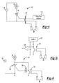
- Figure 4 is a schematic view of a water sense circuit using a gate drive pulse transformer according to the principles of the present disclosure
- Figure 5 is a schematic water sense circuit utilizing an oscillator, transformer, and low level detection comparator according to the principles of the present disclosure
- Figure 6 is a schematic water sense circuit using a line frequency transformer according to the principles of the present disclosure
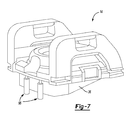
- Figure 7 is a perspective view of a head portion of an industrial shop vacuum, according to the principles of the present disclosure, illustrating the water detection probes
- Figure 8 is a schematic diagram of a electro-mechanical water sense system using a floating core to provide water level detection according to the principles of the present disclosure
- Figure 9 is a schematic circuit diagram of the water sense system utilizing a floating core according to the principles of the present disclosure.
- Figure 10 is a schematic view of a vacuum incorporating a pump according to the principles of the present disclosure.
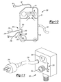
- Figure 11 is a perspective view of a pump according to the principles of the present disclosure.
- Figure 12 is a control diagram for use with the external pump according to the principles of the present disclosure.
- Figure 13 is a flowchart showing a control method according to the principles of the present disclosure.
- the vacuum 10 may include a canister 12 and a vacuum head 14 that closes the canister 12.
- the vacuum head may support a drive motor 16.
- the drive motor 16 may support a suction fan 18, which may be provided in a fan chamber 20 of the vacuum head 14.
- the fan chamber 20 may be in fluid communication with an exhaust port 22 and an intake port 24.
- the intake port 24 may be covered by a filter assembly 26 situated in a filter housing 28 of a vacuum head 14.
- a motor 16 when powered up, may rotate the suction fan 18 to draw air into the suction inlet opening 30 and through the canister 12, through the filter assembly 26, through the intake port 24 and into the fan chamber 20.
- the suction fan 18 may push the air in the fan chamber 20 through the exhaust port 22 and out of the vacuum 10.
- a hose 32 can be attached to the inlet opening 30.
- the canister 12 can be supported by wheels 34.
- the wheels 34 can include caster wheels, or the wheels can alternatively be supported by an axle.
- a filter cleaning device 34 is provided including a filter cleaning motor 36 drivingly connected to a filter cleaning mechanism 38.
- the filter cleaning mechanism 38 can take many forms, and can include an eccentrically driven arm 40 having fingers 42 engaging the filter 26.
- the filter cleaning device 34 can be driven to traverse across the filter 26 to cause debris that is stuck to the filter to be loosened up and fall into the canister 12.
- the arm 40 is connected to an eccentric drive member 44 which is connected to motor 36 and, when rotated, causes the arm 40 and fingers 42 to traverse across the surface of the filter 26.
- the electronics 50 generally include a power cord 52 extending from the vacuum and adapted for connection with an AC power source 54.
- the power cord 52 can include a plug 56 having a two-prong or three-prong connection as is known in the art, as is shown in Figure 2 .
- the power cord 52 is connected to a power source circuit 60.
- An electrical isolation circuit 62 is provided in communication with the power source circuit 60 for providing a low voltage output VCC, as will be described in greater detail herein.
- a microcontroller 64 is provided in communication with the electrical isolation circuit 62 for receiving a low voltage supply VCC therefrom. The microcontroller 64 provides control signals to a filter cleaning circuit 66 and a vacuum circuit 68.
- a power tool sense circuit 70 is provided in communication with the microcontroller 64 for providing a signal to the microcontroller 64 regarding operation of a power tool that is plugged into an outlet 72 that can be disposed on the power tool 10.
- the outlet 72 can be connected to the power cord 52 as indicated by nodes L, N.
- a water sense circuit 74 is provided in communication with the microcontroller 64 for providing a signal ("WATER") to the microcontroller 64 that the water level in the canister 12 has reached a predetermined level for deactivating the vacuum source in order to prevent water from being drawn into the vacuum filter 26.
- a first switch S1 and a second switch S2 are provided for controlling operation of the vacuum motor 16.
- the switches S1 and S2 are connected to connectors A, B and A, C, respectively, wherein connectors B and C are connected to ratio circuits 76, 78, respectively.
- Connector A provides an input signal to the microcontroller 64 indicative of the activation state of switch S1 and switch S2 in order to provide four modes of operation utilizing the two switches S1 and S2 while providing just a single input into the microcontroller 64.
- Table 1 provides a list of the mode selection possibilities with switches S1 and S2 in the different activation states.
- Table 1 User Switch Position S1 S2 Microcontroller Input VCC Ratio 1 0 0 0 * VCC 2 0 1 (1/3) * VCC 3 1 0 (4/5) * VCC 4 1 1 (5/8) * VCC
- the ratio circuit 76, 78 provide different ratio input signals as a function of the low voltage supply VCC.
- VCC low voltage supply
- Table 1 when both switch S1 and switch S2 are open, a zero ratio VCC signal is received.
- switch S1 When switch S1 is open and switch S2 is closed, a 1/3 ratio VCC signal is provided.
- switch S1 is closed and switch S2 is open, a 4/5 VCC ratio signal is provided, and when both switches S1 and S2 are closed, a 5/8 VCC ratio signal is provided to the microcontroller 64.
- the ratios are determined by the resistance levels of the resistors R17-R20 provided in the ratio circuits 76, 78.
- Ratios, number of switches, and number of resistors can vary for inputs other than 4.
- four user selectable modes are provided, thereby simplifying the microcontroller input and reducing the cost of the microcontroller.
- the four user selectable modes can include position (1) vacuum off, power outlet is off, auto filter clean is off and filter clean push button is off; position (2) vacuum on, power outlet is off, auto filter clean is off and filter clean push button is on; position (3) vacuum on, power outlet off, auto filter clean is on and filter clean push button is on; and position (4) (auto mode) vacuum is controlled by outlet, auto filter clean is on and filter clean push button is on.
- a filter clean switch 80 is also provided for providing a signal to the microcontroller 64 for operating the filter cleaning device via activation of the filter cleaning circuit 66.
- the filter cleaning circuit 66 includes an opto-coupler 82 which can be activated by a low voltage signal from the microcontroller 64.
- the opto-coupler 82 provides an activation signal to a triac 84.
- the triac 84 conducts electricity to the filter cleaning motor 36 for activating the filter cleaning device 34.
- the opto-coupler 82 requires only a low power input for holding the triac 84 active. Additionally, the triac may be held continuously active for a time period then turned inactive, or pulsed active/inactive for a timer period, or the triac may be replaced by an SCR and driven with DC in a similar manner just described.
- the microcontroller 64 can also provide a control signal to the vacuum circuit 68.
- the vacuum circuit 68 is provided with an opto-coupler 86 which receives a low voltage signal from the micro-controller 64.
- the opto-coupler 86 can provide an activation voltage to a triac 88 which is held active by the voltage supplied by the opto-coupler 86 to provide electricity to the vacuum motor 16.
- the opto-coupler 86 requires only a low power input for holding the triac 88 active.
- the power tool sense circuit 70 is provided with a current transformer 90 that senses current passing through an electrical connection to the power outlet 72 that supplies power to a power tool that can be plugged into the power outlet 72.
- the current transformer 90 provides a signal to the microcontroller 64 indicative to the activation state of a power tool plugged into the outlet 72.
- the microcontroller 64 can automatically activate the vacuum motor 16 for driving the vacuum source.
- the vacuum motor 16 can be activated to assist in vacuuming debris that is created by the use of the power tool.
- the microcontroller 64 can delay deactivation of the vacuum motor 16 after the power tool is deactivated, to allow for the vacuum 10 to collect debris for a predetermined period of time after the power tool is deactivated.
- the water sense circuit 74 includes a pair of water sense probes 96 disposed within the canister 12 of the vacuum 10. As illustrated in Figure 7 , probes 96 can be connected to vacuum head 14 and can be suspended within the canister 12 below the level of the filter 26. A buffer device 98 buffers the high impedance water sense input. The microcontroller on its own is unreliable in measuring the high impedance water sense input. The output of the buffer device or amplifier 98 goes to an analog input to the microcontroller 64. The microcontroller software determines the analog level to detect water sense.
- the water sense probes 96 can be brass probes mounted in the vacuum's canister 12. Water contacting between the probes will be detected by the water sense circuit 74 as a lower impedance.
- the electrical isolation circuit 62 is provided to eliminate shock hazard. Three components provide isolation including the power supply transformer 100 as well as the current transformer 90 and the opto-couplers 82, 86.
- the power supply transformer 100 provides a reduced voltage output from the power source 54.
- a five volt reduced power supply VCC can be provided by the electrical isolation circuit 62 from the AC line voltage source 54.
- the circuit 60 previous to the transformer is the control circuit for the switching supply.
- the transformer provides isolation and is part of the switching supply.
- the five volt regulator takes the isolated control circuit output and reduces it to +5V regulated.
- the low voltage power supply VCC is utilized by the microcontroller 64 for providing signals to the opto-couplers 82, 86 of the filter cleaning circuit 66 and vacuum circuit 68 as well as supplying power to the water sense circuit 74. Furthermore, the ratio switch circuits 76, 78 are supplied with the low voltage VCC power supply.
- an alternative water sense circuit 110 is provided for sensing a water level in the canister 12 for deactivating the vacuum motor 16.
- a gate drive pulse transformer 112 is provided along with a pulse drive oscillator 114.
- the oscillator provides a gate signal to the triac 116. When the water level touches the probes, it essentially shorts out the gate signal turning off the triac 116. When the triac 116 is turned off, the voltage supply 54 to the vacuum motor 16 is interrupted.
- the circuit 120 includes an oscillator 122, a transformer 124, and a low level detection in the form of a comparator 126 with no water detected by the water probes 96, the oscillator signal 122 is seen at the op-amp 126.
- the oscillator signal is eliminated from the op-amp input that is providing a signal to a microcontroller of a detected high water level.
- the water sense circuit 130 includes a line frequency transformer 132 to provide water detection.
- the triac 134 operates at near full voltage.
- the triac gate signal is shorted to common and the triac 136 turns off thereby disconnecting the vacuum motor 16 from the power source 54.
- Each of the water sense circuits provide water sense with isolation.
- a circuit can also be provided with a latching system, meaning when water is detected, the circuit maintains the water detected state even if the water level recedes, until power is cycled or some user reset is enabled.
- a triac is shown as the control device.
- other devices such as FETs, IGBTs.
- the electromechanical water sense system 140 includes a normally closed relay 142 mounted to a hollow boss 144 with a floating core 146.
- the floating core 146 is on the hollow side of the boss 144.
- a relay coil 150 is constantly supplied with power but cannot activate (i.e., open the context) because no core is present.
- the float 148 will rise and the core 146 will insert into the hollow boss 144.
- the core will allow the relay 142 to change states and open the contact and thereby removing power from the vacuum motor 16.
- the relay will not change states until power is removed and the water level is reduced. This latching feature prevents the vacuum motor power from cycling on/off and causing water to enter the motor 16.
- the system requires no extra electronics and provides an economical solution for low-cost vacuums.
- an example vacuum 200 may include a canister 12 and a head 14 that closes the canister 12.
- the head 14 may support a vacuum motor 16.
- the vacuum motor 16 may support a suction fan 18.
- the vacuum motor 16 may be connected to a power source via a power cord 52 with a power plug 56.
- the vacuum motor 16 when powered up by closing a switch (not shown), may rotate the suction fan 18, thereby drawing air from the canister 12. In this way, debris (including liquids) may be drawn through a hose 32 and into the canister 12.
- the canister 12 may include a recess 202 in which an eternal pump 204 may be removably mounted.
- the canister 12 and/or the external pump 204 may include conventional features (i.e., fasteners, latches, ribs, and/or straps) that provisionally secure the external pump 204 in the recess 202.
- a conduit 206 may be connected between an outlet 208 provided in the canister 12 and an inlet 210 of the external pump 204.
- the external pump 204 may include an outlet 212 for connection to a hose 214.
- the external pump 204 may include an electric motor (not shown), which may be connected to a power source via a power cord 216 with a power plug 218, and a switch 220 for actuating the external pump 204.
- a mechanism i.e., a check valve
- the external pump 204 may include a power outlet 222 that is electrically connected to the power cord 216.
- the power outlet 222 may receive the power plug 56 of the vacuum motor 16. Accordingly, a user may plug the power plug 56 of the external pump 204 into a power outlet in a wall (or some other power source), and plug the power plug 56 of the vacuum motor 16 into the power outlet 222 of the external pump 204. In this way, the vacuum motor 16 and the external pump 204 may be driven with only a single power cord (i.e., the power cord 216) being physically connected to a power source, thereby reducing power cord management issues and/or power outlet availability issues.
- the vacuum motor 16 and the external pump 204 may be independently activated via respective switches.
- appropriate control circuitry and/or sensors can be utilized to provide numerous and varied operational features.
- a controller 310 may be connected to the vacuum motor 16, the switch 220 of the external pump 204, and a sensor 320.
- the switch 80 could be closed by the operator to enable the controller 310 to activate the external pump 204 based on inputs from the sensor 320.
- the sensor 320 may be a level sensor detecting the level of liquid in the cannister12 or alternatively a flow sensor detecting a flow of liquid through the external pump 204. In this way, when the switch 220 is closed, the controller 310 may intermittently activate the external pump 204 based on the inputs from the sensor 320, which may indicate the presence of liquid in the canister 12.
- FIG 13 schematically illustrates an example flow diagram of the control process that may be exercised by the controller 310 depicted in Figure 12 .
- the control process may be initiated when the switch 220 is closed (S100).
- the controller 310 may check the status of the sensor 320 (S200). Based on inputs from the sensor 320, the controller 310 may determine whether pumping is required (S300). If so, then the controller 310 may determine whether the pump 204 is running (S400). If the pump 204 is not running, then the controller 310 may activate the pump 204 (S500). The controller 310 may activate the pump 204 for a determined amount of time, and then loop back to check the status of the sensor (S200). If the pump 204 is running (at S400), then the controller 310 may continue to activate the pump 204, and then loop back to check the status of the sensor (S200).
- the controller 310 may determine whether the pump 204 is running (S600). If so, then the controller 310 may deactivate the pump 204 (S700), and then loop back to check the status of the sensor 320 (S200). If the pump 204 is not running (at S600), then the controller 310 may loop back to check the status of the sensor 320 (S200).
- the vacuum motor 16 may draw power through the external pump 204 by virtue of the power plug 56 of the power cord 52 being plugged into the power outlet 222 of the external pump 204.
- the vacuum motor 16 may draw power through the external pump via an auxiliary power path (which could be provided in addition to the power plug 56 and the power cord 52).
- the vacuum motor 16 may be connected to an auxiliary power line (not shown) with an auxiliary power plug (not shown) mounted in the recess 202 of the canister 12.
- the auxiliary power line may be embedded in walls of the head 14 and the canister 12.
- a connector may be provided in the auxiliary power line to facilitate removal of the head 14 from the canister 12.
- the external pump 204 may include a power outlet (in addition to, or instead of, the power outlet 222 depicted in Figure 11 ) provided on the back face of the external pump 204.
- a power outlet in addition to, or instead of, the power outlet 222 depicted in Figure 11
- the auxiliary power plug of the vacuum motor 16 would be plugged into the power outlet on the rear face of the external pump 204 upon mounting the external pump 204 in the recess 202 of the canister 12.
- the vacuum motor 16 may draw power through the external pump 204 by virtue of the power plug 56 of the power cord 52 being plugged into the power outlet 222 of the external pump 204.
- the vacuum 200 may include an onboard power outlet that may be electrically connected to the power cord 52.
- the onboard power socket may received the power plug 218 of the external pump 204.
- a user may plug the power plug 56 of the vacuum motor 16 into the power outlet in a wall (or some other power source), and plug the power plug 218 of the external pump 204 into the onboard power outlet of the vacuum 200.
- the vacuum motor 16 and the external pump 204 may be driven with only a single power cord (i.e., the power cord 52) being physically connected to a power source.
Landscapes
- Engineering & Computer Science (AREA)
- Mechanical Engineering (AREA)
- Control Of Positive-Displacement Pumps (AREA)
- Electric Vacuum Cleaner (AREA)
- Measurement Of Levels Of Liquids Or Fluent Solid Materials (AREA)
- Control Of Non-Positive-Displacement Pumps (AREA)
- Water Treatment By Sorption (AREA)
Applications Claiming Priority (1)
| Application Number | Priority Date | Filing Date | Title |
|---|---|---|---|
| US11/870,950 US8516650B2 (en) | 2007-10-11 | 2007-10-11 | Vacuum electronic water sense circuit |
Publications (3)
| Publication Number | Publication Date |
|---|---|
| EP2055221A2 true EP2055221A2 (de) | 2009-05-06 |
| EP2055221A3 EP2055221A3 (de) | 2011-06-01 |
| EP2055221B1 EP2055221B1 (de) | 2014-12-03 |
Family
ID=40202014
Family Applications (1)
| Application Number | Title | Priority Date | Filing Date |
|---|---|---|---|
| EP08165590.4A Not-in-force EP2055221B1 (de) | 2007-10-11 | 2008-10-01 | Industriestaubsauger mit einer Wassererkennungsschaltung |
Country Status (3)
| Country | Link |
|---|---|
| US (1) | US8516650B2 (de) |
| EP (1) | EP2055221B1 (de) |
| CN (1) | CN201312778Y (de) |
Cited By (2)
| Publication number | Priority date | Publication date | Assignee | Title |
|---|---|---|---|---|
| EP3335611A1 (de) * | 2016-12-14 | 2018-06-20 | Hako GmbH | Bodenreinigungsmaschine mit füllstandsmessung für schmutzwassertank |
| EP4717134A1 (de) * | 2024-09-30 | 2026-04-01 | Techtronic Cordless GP | Bodenreinigungsgerät |
Families Citing this family (11)
| Publication number | Priority date | Publication date | Assignee | Title |
|---|---|---|---|---|
| AU2011265435B2 (en) * | 2010-12-29 | 2014-04-24 | Bissell Inc. | Cleaning implement with mist generating system |
| US9305727B2 (en) | 2014-02-12 | 2016-04-05 | Emerson Electric Co. | Systems, methods, and apparatuses for controlling the power supply of a vacuum cleaner motor |
| CA3104286A1 (en) | 2018-06-22 | 2019-12-26 | Bissell Inc. | Apparatus for cleaning a surface |
| CN110786781B (zh) * | 2018-08-03 | 2022-07-08 | 添可智能科技有限公司 | 吸尘器控制系统、方法及装置 |
| CN112312811B (zh) | 2018-08-27 | 2023-01-10 | 创科地板护理技术有限公司 | 地面清洁器 |
| EP3721776B1 (de) * | 2019-04-09 | 2024-05-29 | Hilti Aktiengesellschaft | Nass-sauger und anordnung von komponenten in einem solchen nass-sauger |
| US11589720B2 (en) | 2019-09-11 | 2023-02-28 | Techtronic Floor Care Technology Limited | Floor cleaner |
| WO2021141778A1 (en) * | 2020-01-06 | 2021-07-15 | Techtronic Cordless Gp | Cleaning system with full recovery tank shutoff |
| US12467461B2 (en) * | 2020-01-08 | 2025-11-11 | Water Technology, Llc | Fluid vacuum pump |
| AU2023424754A1 (en) | 2023-01-20 | 2025-07-31 | Sharkninja Operating Llc | Extraction cleaner |
| US12624688B2 (en) * | 2024-04-16 | 2026-05-12 | Oleg Malyshkin | Sump pump system and method for operating thereof |
Citations (1)
| Publication number | Priority date | Publication date | Assignee | Title |
|---|---|---|---|---|
| US5920955A (en) | 1996-07-12 | 1999-07-13 | Shop Vac Corporation | Self-evacuating vacuum cleaner |
Family Cites Families (83)
| Publication number | Priority date | Publication date | Assignee | Title |
|---|---|---|---|---|
| US1864622A (en) * | 1930-10-25 | 1932-06-28 | Alfred W Sutherland | Apparatus for cleaning vacuum cleaner bags |
| US2522882A (en) * | 1945-08-14 | 1950-09-19 | Electrolux Corp | Vacuum cleaner |
| BE479028A (de) * | 1946-07-12 | |||
| US3009188A (en) * | 1957-09-27 | 1961-11-21 | Elmer A Martin | Portable suction and blower unit |
| US3236032A (en) * | 1962-01-22 | 1966-02-22 | Hitachi Ltd | Vacuum cleaner with filter cleaning means |
| US3320726A (en) * | 1966-04-18 | 1967-05-23 | Parks Cramer Co | Traveling textile cleaner with forced air filter cleaning means |
| DE1964261C3 (de) * | 1969-12-22 | 1973-06-28 | Matsushita Electric Ind Co Ltd | Elektromotorisch angetriebener Staubsauger |
| US3708962A (en) * | 1970-03-20 | 1973-01-09 | Sanyo Electric Co | Vacuum cleaner |
| US3656083A (en) * | 1970-09-01 | 1972-04-11 | Richard G Brook | Electrical safety device |
| US3695006A (en) * | 1970-10-23 | 1972-10-03 | Dynamics Corp America | Vacuum cleaner |
| US3800205A (en) * | 1973-05-15 | 1974-03-26 | Cutler Hammer Inc | Sump pump control system |
| US3936904A (en) * | 1974-06-03 | 1976-02-10 | Whirlpool Corporation | Vacuum cleaner clogged condition indicator |
| US4021879A (en) * | 1975-11-28 | 1977-05-10 | Consolidated Foods Corporation | Constant performance vacuum cleaner |
| US4070078A (en) * | 1977-03-02 | 1978-01-24 | Reliance Products Corporation | Safety cover for an electrical outlet |
| US4179768A (en) * | 1977-03-16 | 1979-12-25 | Aktiebolaget Electrolux | Vacuum dumping arrangement for a wet/dry vacuum cleaner |
| US4266257A (en) * | 1978-10-02 | 1981-05-05 | Johnson Controls, Inc. | Motor over-heating protection circuit |
| US4321826A (en) * | 1980-04-28 | 1982-03-30 | Bibbee William C | Flowmeter for fluid flow through weirs and parshall flumes |
| US4302624A (en) * | 1980-05-16 | 1981-11-24 | Newman Fredric M | Electric wall outlet protector |
| US4357729A (en) * | 1981-01-26 | 1982-11-09 | Whirlpool Corporation | Vacuum cleaner control |
| US4465485A (en) * | 1981-03-06 | 1984-08-14 | Becton, Dickinson And Company | Suction canister with unitary shut-off valve and filter features |
| DE3277957D1 (en) * | 1981-10-26 | 1988-02-11 | Pico Electronics Ltd | Electrical appliance control |
| US4398316A (en) * | 1982-01-13 | 1983-08-16 | The Scott & Fetzer Company | Speed selector switch |
| US4611365A (en) * | 1983-02-12 | 1986-09-16 | Matsushita Electric Industrial Co., Ltd. | Vacuum cleaner |
| DE3410817A1 (de) | 1984-03-23 | 1985-10-03 | Esta Apparatebau GmbH & Co KG, 7913 Senden | Reinigungsgeraet fuer schwimmbaeder oder dgl. |
| US4654924A (en) * | 1985-12-31 | 1987-04-07 | Whirlpool Corporation | Microcomputer control system for a canister vacuum cleaner |
| US4723337A (en) * | 1986-12-09 | 1988-02-09 | Shumpert & Ellison, Inc. | High pressure carpet or rug cleaning apparatus |
| US4864680A (en) * | 1987-03-20 | 1989-09-12 | Bissell, Inc. | Liquid extraction surface cleaning apparatus |
| US4841595A (en) * | 1987-08-07 | 1989-06-27 | The Kent Company | Vacuum pump-out system for wet/dry vacuum cleaner |
| DE8801599U1 (de) | 1988-02-09 | 1988-04-21 | Kurz, Gerhard, 7262 Althengstett | Elektromotorisch angetriebener Flüssigkeitssauger mit Schutzschaltung |
| US4825140A (en) * | 1988-05-03 | 1989-04-25 | St Louis Raymond F | Power tool/vacumm cleaner power control |
| US5099157A (en) * | 1988-06-10 | 1992-03-24 | Milwaukee Electric Tool Corporation | Master/slave circuit employing triacs |
| DE3822633A1 (de) * | 1988-07-05 | 1990-01-18 | Bsg Schalttechnik | Vorrichtung mit einschaltautomatik fuer ein nebengeraet bei inbetriebnahme eines hauptgeraetes |
| DE3902647A1 (de) * | 1989-01-21 | 1990-08-02 | Interlava Ag | Vorrichtung zur automatischen saugleistungssteuerung eines staubsaugers |
| SE463070B (sv) * | 1989-02-14 | 1990-10-08 | Electrolux Ab | Anordning vid en dammsugare |
| US5111188A (en) * | 1989-10-05 | 1992-05-05 | Harry E. Turloff | Electronic fluid-level sensor with three state indicator |
| DE4014443A1 (de) * | 1990-05-05 | 1991-11-07 | Duepro Ag | Fluessigkeitssauger |
| JP2983658B2 (ja) * | 1991-02-14 | 1999-11-29 | 三洋電機株式会社 | 電気掃除機 |
| DE4107535A1 (de) * | 1991-03-08 | 1992-09-10 | Yoo Byoung Hyouk | Filterloser fluessigkeitsfilterungs-vakuumreiniger |
| JP2553485Y2 (ja) * | 1991-04-19 | 1997-11-05 | 株式会社マキタ | 集塵機の外部電源供給機構 |
| JPH0662991A (ja) * | 1992-08-21 | 1994-03-08 | Yashima Denki Co Ltd | 電気掃除機 |
| DK140892D0 (da) * | 1992-11-24 | 1992-11-24 | Lego As | Elektrisk omskifter |
| US5455983A (en) * | 1993-01-15 | 1995-10-10 | The Hoover Company | Wet/dry utility vacuum cleaner |
| GB9311187D0 (en) * | 1993-05-29 | 1993-07-14 | Schlumberger Ind Ltd | Fluid level sensing systems |
| DE4327070C1 (de) * | 1993-08-12 | 1995-04-06 | Gerhard Kurz | Vorrichtung zur Regelung der Leistungsaufnahme eines Staubsaugers |
| US5449988A (en) * | 1994-03-30 | 1995-09-12 | U.S. Products, Inc. | Vacuum motor control including float switch and in-rush current restraint |
| US5465455A (en) * | 1994-05-27 | 1995-11-14 | Allen; Harold | Overload controlled wet and dry vacuum apparatus |
| DE9413499U1 (de) * | 1994-08-22 | 1994-10-27 | Unimeß Meßtechnische Geräte GmbH, 61239 Ober-Mörlen | Füllstandsmeßvorrichtung, insbesondere Überfüllsicherung für einen Flüssigkeitstank |
| US5541457A (en) * | 1995-06-12 | 1996-07-30 | Morrow; Rodney J. | Electrical current actuated accessory outlet |
| CA2175268C (en) | 1995-12-07 | 2001-11-20 | George E. Hendrix | Portable electric tool vacuum cleaner control |
| US5715568A (en) * | 1995-12-12 | 1998-02-10 | Shop Vac Corporation | Vacuum apparatus having a pump for discharging liquid therefrom |
| US5918344A (en) * | 1996-07-12 | 1999-07-06 | Shop Vac Corporation | Self-evacuating vacuum cleaner |
| US6009596A (en) | 1996-07-12 | 2000-01-04 | Shop Vac Corporation | Self-evacuating vacuum cleaner |
| US5850668A (en) * | 1996-07-12 | 1998-12-22 | Shop Vac Corporation | Self-evacuating vacuum cleaner |
| US5954863A (en) * | 1996-11-18 | 1999-09-21 | Loveless; Michael L. | Wet and dry vacuum with float valve system |
| US5747973A (en) * | 1996-12-11 | 1998-05-05 | Shop Vac Corporation | Current regulating switch circuit |
| US5784753A (en) * | 1996-12-26 | 1998-07-28 | Minuteman International, Inc. | Carpet spotting machine with thermostatic protection against overflow |
| US6029309A (en) | 1997-04-08 | 2000-02-29 | Yashima Electric Co., Ltd. | Vacuum cleaner with dust bag fill detector |
| US5955791A (en) * | 1997-04-14 | 1999-09-21 | Irlander; James E. | Master/slave circuit for dust collector |
| US6008608A (en) | 1997-04-18 | 1999-12-28 | Emerson Electric Co. | User operated switch and speed control device for a wet/dry vacuum |
| US6026539A (en) | 1998-03-04 | 2000-02-22 | Bissell Homecare, Inc. | Upright vacuum cleaner with full bag and clogged filter indicators thereon |
| DE19813434A1 (de) | 1998-03-27 | 1999-09-30 | Proair Geraetebau Gmbh | Naßsauger |
| US6112366A (en) | 1999-01-20 | 2000-09-05 | Shop Vac Corporation | Outlet priming self-evacuation vacuum cleaner |
| US6453507B1 (en) | 1999-03-16 | 2002-09-24 | Gene Wilson Gilbert | Self contained, self-cleaning, wet/dry vacuum machine |
| US6119304A (en) | 1999-03-30 | 2000-09-19 | Shop Vac Corporation | Self-evacuating vacuum cleaner |
| US6249933B1 (en) | 1999-08-26 | 2001-06-26 | Shop Vac Corporation | Pump having sealless shaft |
| US6222285B1 (en) * | 1999-09-07 | 2001-04-24 | Shop Vac Corporation | Intelligent switch control circuit |
| DE60121652T2 (de) | 2000-03-24 | 2007-07-26 | Sharp K.K. | Elektrischer Staubsauger |
| US6457205B1 (en) | 2000-05-24 | 2002-10-01 | Fantom Technologies Inc. | Vacuum cleaner having a plurality of power modes |
| US6481049B1 (en) | 2000-06-07 | 2002-11-19 | Shop Vac Corporation | Self-evacuating vacuum cleaner |
| US6378164B1 (en) | 2000-07-18 | 2002-04-30 | Shop Vac Corporation | Pump inlet fitting |
| US6812847B1 (en) | 2000-08-25 | 2004-11-02 | The Hoover Company | Moisture indicator for wet pick-up suction cleaner |
| US6832407B2 (en) | 2000-08-25 | 2004-12-21 | The Hoover Company | Moisture indicator for wet pick-up suction cleaner |
| US6610952B2 (en) | 2000-12-15 | 2003-08-26 | Shop Vac Corporation | Vacuum cleaner actuator switch |
| US6569218B2 (en) | 2001-03-08 | 2003-05-27 | David Edmond Dudley | Self spin-cleaning canister vacuum |
| DE10164204A1 (de) | 2001-12-27 | 2003-07-17 | Siemens Linear Motor Systems G | Schutzeinrichtung für Elektromotor mit Sensor und Auswerteeinheit |
| US7152277B2 (en) * | 2003-03-13 | 2006-12-26 | Samsung Gwangju Electronics Co., Ltd. | Filter assembly for cyclone type dust collecting apparatus of a vacuum cleaner |
| KR100518804B1 (ko) * | 2003-03-31 | 2005-10-06 | 삼성광주전자 주식회사 | 사이클론집진장치의 필터청소기구 |
| US6758874B1 (en) | 2003-05-09 | 2004-07-06 | John P. Hunter, Jr. | Rotating filter feature for wet/dry vacuum cleaner |
| GB0318284D0 (en) * | 2003-08-05 | 2003-09-10 | Black & Decker Inc | Hand-held vacuum cleaner |
| US7208024B2 (en) * | 2003-12-08 | 2007-04-24 | The Hoover Company | Floor care appliance with filter cleaning system |
| US7351269B2 (en) * | 2003-12-22 | 2008-04-01 | Lau Kwok Yau | Self cleaning filter and vacuum incorporating same |
| KR100539762B1 (ko) * | 2004-03-09 | 2006-01-10 | 엘지전자 주식회사 | 진공청소기의 필터 청소 장치 |
| KR100585692B1 (ko) * | 2004-04-06 | 2006-06-07 | 엘지전자 주식회사 | 진공청소기의 먼지통 |
-
2007
- 2007-10-11 US US11/870,950 patent/US8516650B2/en active Active
-
2008
- 2008-10-01 EP EP08165590.4A patent/EP2055221B1/de not_active Not-in-force
- 2008-10-13 CN CNU2008202340811U patent/CN201312778Y/zh not_active Expired - Fee Related
Patent Citations (1)
| Publication number | Priority date | Publication date | Assignee | Title |
|---|---|---|---|---|
| US5920955A (en) | 1996-07-12 | 1999-07-13 | Shop Vac Corporation | Self-evacuating vacuum cleaner |
Cited By (2)
| Publication number | Priority date | Publication date | Assignee | Title |
|---|---|---|---|---|
| EP3335611A1 (de) * | 2016-12-14 | 2018-06-20 | Hako GmbH | Bodenreinigungsmaschine mit füllstandsmessung für schmutzwassertank |
| EP4717134A1 (de) * | 2024-09-30 | 2026-04-01 | Techtronic Cordless GP | Bodenreinigungsgerät |
Also Published As
| Publication number | Publication date |
|---|---|
| US20090094778A1 (en) | 2009-04-16 |
| EP2055221B1 (de) | 2014-12-03 |
| CN201312778Y (zh) | 2009-09-23 |
| US8516650B2 (en) | 2013-08-27 |
| EP2055221A3 (de) | 2011-06-01 |
Similar Documents
| Publication | Publication Date | Title |
|---|---|---|
| EP2055221B1 (de) | Industriestaubsauger mit einer Wassererkennungsschaltung | |
| US7644469B2 (en) | Vacuum electronics isolation method | |
| US8266761B2 (en) | Vacuum electronic switch detection system | |
| EP1955637B1 (de) | Erkennung eines Vakuum-Elektrowerkzeugs | |
| US8443485B2 (en) | Outlet box for power tool sense | |
| US12377378B2 (en) | Combination vacuum and air purifier system and method | |
| US20130019901A1 (en) | Vacuum cleaner and method for operating a vacuum cleaner | |
| JP2004033628A (ja) | 電気掃除機 | |
| JP2003164399A (ja) | 電気掃除機 | |
| KR19990048459A (ko) | 진공청소기의 운반시 자동구동제어장치 | |
| JP3117017B2 (ja) | 電気掃除機 | |
| CN116209381A (zh) | 具有低功率模式的地板清洁器 | |
| JP3874175B2 (ja) | 電気掃除機 | |
| JPH05168574A (ja) | 電気掃除機 | |
| KR970011918B1 (ko) | 진공청소기의 운전제어장치 | |
| JP2010194208A (ja) | 電気掃除機 | |
| JP3874176B2 (ja) | 電気掃除機 | |
| JP3285028B2 (ja) | 電気掃除機 | |
| JPH02152427A (ja) | 電気掃除機 | |
| KR970005516B1 (ko) | 진공청소기에서의 흡입먼지 유무에 따른 구동전원 자동차단장치 및 그 방법 | |
| JP2005006815A (ja) | 電気掃除機 | |
| JPH0458930A (ja) | 電気掃除機 | |
| JPH0618545B2 (ja) | 電気掃除機 | |
| JP2004283215A (ja) | 電気掃除機 | |
| KR19990052625A (ko) | 진공청소기의 상태 감지장치 |
Legal Events
| Date | Code | Title | Description |
|---|---|---|---|
| PUAI | Public reference made under article 153(3) epc to a published international application that has entered the european phase |
Free format text: ORIGINAL CODE: 0009012 |
|
| AK | Designated contracting states |
Kind code of ref document: A2 Designated state(s): AT BE BG CH CY CZ DE DK EE ES FI FR GB GR HR HU IE IS IT LI LT LU LV MC MT NL NO PL PT RO SE SI SK TR |
|
| AX | Request for extension of the european patent |
Extension state: AL BA MK RS |
|
| PUAL | Search report despatched |
Free format text: ORIGINAL CODE: 0009013 |
|
| AK | Designated contracting states |
Kind code of ref document: A3 Designated state(s): AT BE BG CH CY CZ DE DK EE ES FI FR GB GR HR HU IE IS IT LI LT LU LV MC MT NL NO PL PT RO SE SI SK TR |
|
| AX | Request for extension of the european patent |
Extension state: AL BA MK RS |
|
| 17P | Request for examination filed |
Effective date: 20111128 |
|
| AKX | Designation fees paid |
Designated state(s): DE GB IT SE |
|
| 17Q | First examination report despatched |
Effective date: 20130212 |
|
| GRAP | Despatch of communication of intention to grant a patent |
Free format text: ORIGINAL CODE: EPIDOSNIGR1 |
|
| INTG | Intention to grant announced |
Effective date: 20140707 |
|
| GRAS | Grant fee paid |
Free format text: ORIGINAL CODE: EPIDOSNIGR3 |
|
| GRAA | (expected) grant |
Free format text: ORIGINAL CODE: 0009210 |
|
| AK | Designated contracting states |
Kind code of ref document: B1 Designated state(s): DE GB IT SE |
|
| REG | Reference to a national code |
Ref country code: GB Ref legal event code: FG4D |
|
| REG | Reference to a national code |
Ref country code: DE Ref legal event code: R096 Ref document number: 602008035651 Country of ref document: DE Effective date: 20150115 |
|
| PG25 | Lapsed in a contracting state [announced via postgrant information from national office to epo] |
Ref country code: SE Free format text: LAPSE BECAUSE OF FAILURE TO SUBMIT A TRANSLATION OF THE DESCRIPTION OR TO PAY THE FEE WITHIN THE PRESCRIBED TIME-LIMIT Effective date: 20141203 |
|
| REG | Reference to a national code |
Ref country code: DE Ref legal event code: R097 Ref document number: 602008035651 Country of ref document: DE |
|
| PLBE | No opposition filed within time limit |
Free format text: ORIGINAL CODE: 0009261 |
|
| STAA | Information on the status of an ep patent application or granted ep patent |
Free format text: STATUS: NO OPPOSITION FILED WITHIN TIME LIMIT |
|
| 26N | No opposition filed |
Effective date: 20150904 |
|
| PG25 | Lapsed in a contracting state [announced via postgrant information from national office to epo] |
Ref country code: IT Free format text: LAPSE BECAUSE OF FAILURE TO SUBMIT A TRANSLATION OF THE DESCRIPTION OR TO PAY THE FEE WITHIN THE PRESCRIBED TIME-LIMIT Effective date: 20141203 |
|
| PGFP | Annual fee paid to national office [announced via postgrant information from national office to epo] |
Ref country code: GB Payment date: 20190926 Year of fee payment: 12 |
|
| GBPC | Gb: european patent ceased through non-payment of renewal fee |
Effective date: 20201001 |
|
| PG25 | Lapsed in a contracting state [announced via postgrant information from national office to epo] |
Ref country code: GB Free format text: LAPSE BECAUSE OF NON-PAYMENT OF DUE FEES Effective date: 20201001 |
|
| PGFP | Annual fee paid to national office [announced via postgrant information from national office to epo] |
Ref country code: DE Payment date: 20210824 Year of fee payment: 14 |
|
| REG | Reference to a national code |
Ref country code: DE Ref legal event code: R119 Ref document number: 602008035651 Country of ref document: DE |
|
| PG25 | Lapsed in a contracting state [announced via postgrant information from national office to epo] |
Ref country code: DE Free format text: LAPSE BECAUSE OF NON-PAYMENT OF DUE FEES Effective date: 20230503 |